Table of Contents

Related Manuals for Samsung DW5363 Series


Summary of Contents for Samsung DW5363 Series
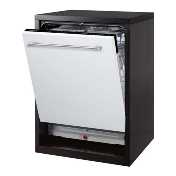
- Page 1 DISHWASHER Model Name : DW5363 Series Model Code : DW5363PGBSL/EF SERVICE Manual DISHWASHER CONTENTS 1. Safety Instructions 2. Features and S eci cations 3. Disassembly and Reassembly 4. Troubleshooting 5. Pcb Diagram 6. Schematic Diagram 7. Reference Refer to the service manual in the GSPN (see the rear cover) for the more information.
-
Page 2: Table Of Contents
CONTENTS 1. Safety Instructions ..............1 1-1. -
Page 3: Safety Instructions
1. SAFETY INSTRUCTIONS 1-1. SAFETY INSTRUCTIONS FOR SERVICE ENGINEERS Warning Caution Warning Before Servicing When servicing electrical parts or harnesses. Make sure to disconnect the circuit breaker or power cable before servicing. ➢ Do not allow consumers to connect several appliances to a single power outlet at the same time. - Page 4 While Servicing Check if the power cable is damaged, attened, cut or otherwise degraded. ➢ Completely remove any dust or foreign material from the housing, wiring and connection parts. ➢ When connecting wires, make sure to connect them using the relevant connectors and check that they are completely connected.
- Page 5 Caution Before Servicing Do not sprinkle water onto the dishwasher directly when cleaning it. ➢ Do not place any containers with water on the dishwasher. ➢ Do not install the dishwasher in a location e posed to snow or rain. ➢...
- Page 6 After Servicing Check the assembled status of the parts. ➢ Check the insulation resistance. ➢ Megger. Check whether the product is level with the oor. Check if there are any deformations in the sink. Check that the dishwasher is rmly installed to the sink. ➢...
-
Page 7: Features
2. FEATURES AND SPECIFICATIONS 2-1. FEATURES Features Description Easy to use Safety Features and Speci cations _ 5... - Page 8 2-2. SPECIFICATIONS(FBI) Model name DW-BG970B Type Water pressure 0.05 - 0.8 Mpa Eco 45 Temperature Eco 53 Water consumption Eco 10L Model name DW-BG770B/D170 Type Water pressure 0.05 - 0.8 Mpa Eco 45 Temperature Eco 60 Water consumption Eco 10L Model name DW-BG570B Type...
- Page 9 SPECIFICATIONS(SBI) Model name DW-SG970T Type Water pressure 0.05 – 0.8 Mpa Temperature Water consumption Eco 10L Model name DW-SG720T/D175 Type Water pressure Temperature Water consumption Eco 10L Model name DW-SG520W Type Water pressure 0.05 – 0.8 Mpa Temperature Water consumption Eco 12L Features and Speci cations _ 7...
- Page 10 SPECIFICATIONS(FS) Model name DW-FG720W Type Water pressure Temperature Eco 10L Water consumption Model name DW-FG520W, D147W, D149STS, D149W Type Water pressure Temperature Eco 12L Water consumption 8 _ Features and Speci cations...
- Page 11 2-2-1. View(FBI, SBI) 2-2-2. View(FS) Features and Speci cations _ 9...
- Page 12 2-3. COMPARING SPECIFICATIONS WITH EXISTING MODELS Install DM-BG970B DW-BG770B/D170 DW-BG570B 0.83 0.97 Capacity Install DW-FG720W DW-FG520W / D147W D149STS / D149W 0.96 0.97 0.97 Capacity 10 _ Features and Speci cations...
- Page 13 Install DW-SG970T DW-SG720T/D175 DW-SG520W 0.83 0.97 mance Capacity tion Features and Speci cations _ 11...
- Page 14 2-4. OPTIONS SPECIFICATIONS Photo Item Code Quantity Remarks 12 _ Features and Speci cations...
- Page 15 MEMO Features and Speci cations _ 13...
-
Page 16: Disassembly And Reassembly
3. DISASSEMBLY AND REASSEMBLY 3-1. TOOLS FOR DISASSEMBLY AND REASSEMBLY Tool image Tool Type Remarks Preparation for parts replacemen 14 _ Disassembly and Reassembly... - Page 17 3-2. STANDARD DISASSEMBLY DRAWINGS WARNING: Always turn off the electric power supply & water supply before servicing Caution : Note: Part Photo Description - Fasten type Fasten type Fasten type - Fasten type Disassembly and Reassembly _ 15...
- Page 18 Part Photo Description Assy control panel & Sub 16 _ Disassembly and Reassembly...
- Page 19 Part Photo Description Control Panel - Door switch Disassembly and Reassembly _ 17...
- Page 20 Part Photo Description Outer Door Dispenser 18 _ Disassembly and Reassembly...
- Page 21 Part Photo Description Outside panel (continued) Disassembly and Reassembly _ 19...
- Page 22 Part Photo Description Outside panel 20 _ Disassembly and Reassembly...
- Page 23 Part Photo Description Door Assembly rope. Caution Disassembly and Reassembly _ 21...
- Page 24 Photo Description Caution Assy cover base Cover base - Leakage sensor 22 _ Disassembly and Reassembly...
- Page 25 Photo Description The dishwasher tub seal prevents water leakage. The seal is tted in a seal channel that lines the rim of the dishwasher tub. Reassemble order Dishwasher Tub Seal Caution Disassembly and Reassembly _ 23...
- Page 26 Part Photo Description Case brake Case brake Caution Caution Caution 24 _ Disassembly and Reassembly...
- Page 27 Part Photo Description Caution softener. Water softener Caution softener. Caution Disassembly and Reassembly _ 25...
- Page 28 Part Photo Description Water Valve 26 _ Disassembly and Reassembly...
- Page 29 Part Photo Description Drain Pump Drain Hose it off. Disassembly and Reassembly _ 27...
- Page 30 Part Photo Description Caution Motor BLDC pump (continued) 28 _ Disassembly and Reassembly...
- Page 31 Part Photo Description Motor (wash) Pump Assembly Turbidity sensor separates. sump . Thermistor Disassembly and Reassembly _ 29...
- Page 32 Part Photo Description Pressure switch Sump Assembly Caution 30 _ Disassembly and Reassembly...
- Page 33 Part Photo Description Dry Assembly (continued) Disassembly and Reassembly _ 31...
- Page 34 Part Photo Description Dry Assembly Main PBA 32 _ Disassembly and Reassembly...
- Page 35 Part Photo Description Fuse service Disassembly and Reassembly _ 33...
- Page 36 Part Photo Description Noise lter service 34 _ Disassembly and Reassembly...
- Page 37 Part Photo Description motor. Synchronous motor & Half load switch service Disassembly and Reassembly _ 35...
- Page 38 3-3. CHECKPOINTS AFTER FINISHING A SERVICE 1. Check the safety device 2. Use authenticated parts only 3. Handling wires 4. The state of screws and nuts 5. Remove foreign material 6. Check for water leakage 7. Check the power cable 8.
- Page 39 MEMO Disassembly and Reassembly _ 37...
-
Page 40: Troubleshooting
4. TROUBLESHOOTING 4-1. ERROR CODES CODES When occur Symptom POSSIBLE CAUSES minutes. 4E-1 minutes. minutes. incorrect. 3 minutes. minutes. minutes. HE-1 C for 10 minutes 38 _ Troubleshooting... - Page 41 CODES When occur Symptom POSSIBLE CAUSES bE-2 bE-3 If se Condition 1) minutes. Condition 2) error occurs. an 1E error occurs. Troubleshooting _ 39...
- Page 42 CODES When occur Symptom POSSIBLE CAUSES minutes. on again. If communicating WARNING 40 _ Troubleshooting...
- Page 43 4-2 TEST MODE 4-2-1 TEST MODE Item Description Entering Test main program Troubleshooting _ 41...
- Page 44 Item Description [Device Test Mode] 42 _ Troubleshooting...
- Page 45 4-2-2 Data Display Mode Item Description Display Water Temperature Troubleshooting _ 43...
-
Page 46: Wash Cycle Table
4-2-3 Wash cycle table Running Program Cycle Cycle Selection Information Water ( ) time (min) Intensive 70 Auto 40 ~ 65 E press 65 11.6 ECO 45 11.8 Quick 50 10.5 Delicate 40 10.1 Prewash Normal 65 ºC items 44 _ Troubleshooting... - Page 47 4-3 MALFUNCTION TABLE Error Error type Checking method Corrective actions mode Water error 5 minutes. Water 4E-1 error Troubleshooting _ 45...
- Page 48 Error Error type Checking method Corrective actions mode sensor. sensor. Error moisture. error connector 46 _ Troubleshooting...
- Page 49 Error Error type Checking method Corrective actions mode connectors. error connector. error error Troubleshooting _ 47...
- Page 50 Error Error type Checking method Corrective actions mode sensing positions. state. error Sensor connector. error 48 _ Troubleshooting...
- Page 51 Error Error type Checking method Corrective actions mode connector. 125.814 Error 98.360 77.480 61.477 49.120 39.510 31.985 26.053 21.347 17.590 14.573 12.136 10.157 8.541 connector. Comm- unication error pressure sensor connectors. error Troubleshooting _ 49...
- Page 52 Error Error type Checking method Corrective actions mode connectors error motor connectors. Motor Comm- unication error 50 _ Troubleshooting...
- Page 53 Error Error type Checking method Corrective actions mode connectors. connectors. moisture. error connector part. part. error Troubleshooting _ 51...
- Page 54 Error Error type Checking method Corrective actions mode error error Motor. function error 52 _ Troubleshooting...
- Page 55 Error Error type Checking method Corrective actions mode connector. is not function error Connector Connector start. Troubleshooting _ 53...
- Page 56 Error Error type Checking method Corrective actions mode error Caution operate. Caution 54 _ Troubleshooting...
- Page 57 MEMO Troubleshooting _ 55...
-
Page 58: Pcb Diagram
5. PCB DIAGRAM 5-1. DETAILED SPECIFICATION AND DESCRIPTIONS FOR CONNECTORS AND RELAY TERMINALS (MAIN PBA) CN2 (BLDC) CN2 (BLDC) CN12 (Micom Write) CON12 CON7 (SUB Communication) CN14 (POWER RELAY) CN13 CON5 CON4 CN14 (HEATER RELAY) (POWER RELAY) 56 _ PCB Diagram... - Page 59 5-2. DETAILED SPECIFICATION AND DESCRIPTIONS FOR CONNECTORS AND RELAY TERMINALS (FS SUB PBA) 8. TEST PCB Diagram _ 57...
- Page 60 5-3. DETAILED SPECIFICATION AND DESCRIPTIONS FOR CONNECTORS AND RELAY TERMINALS (SUB PBA) CON3 1. Common 1 2. Common 2 3. Common 3 4. Common 4 CON4 CON2 CON3 4. ST_SCL 5. ST_SCL 8. TEST 58 _ PCB Diagram...
- Page 61 5-4. DETAILED SPECIFICATION AND DESCRIPTIONS FOR CONNECTORS AND RELAY TERMINALS (TOUCH PBA) CON1 4. ST_SCL CON1 5. ST_SCL PCB Diagram _ 59...
-
Page 62: Schematic Diagram
6. SCHEMATIC DIAGRAM 6-1. MAIN CONTROL WATERSOFTNER_DC POWER CORD AC2_CHK AC2_CHK POWER DGND DGND DGND +12V 100nF 275V 18x6x12 DF06S 600V AGND 0402-001298 DGND 22uF SF26 TURBID-R LEAKAGE 500V 400V 2A PTC1 2.2nF 0402-001624 OVER-FLOW 250V 1000uF 100nF 4.7K J 0.125W 6.3A 100nF 2201-000322... - Page 63 6-2. SUB PBA (FS MODEL) BUZZER +12V DSP1 0.25W 0.25W 330J 0.25W 0.25W 0504-001008 0501-000467 0.2W 0.25W 330J 0.25W 0.35W RN2427 MMBT3906 BUZZER_POWER 330J 0.25W 0.25W BUZZER_POWER 2.2K J 0.125W 0.25W 330J 0.25W 2007-000493 330J 0.25W 0.25W DISPLAY-1 DISPLAY-1 0.25W 330J 0.25W KRC246S...
- Page 64 6-3. SUB PBA (FBI MODEL) +12V BUZZER DISPLAY LOAD_TEST KRC246S 0.125W 0.2W +12V 0.25W 680 J 0.25W 0.25W 680 J 0.25W 0504-001008 2007-000872 0.2W 0.25W 0.125W 4.7K 0.35W RN2427 MMBT3906 SMW250-10 BUZZER_POWER 0.25W BUZZER_POWER 3711-000577 KRC246S 0.2W 0504-001080 +12V 2.0KHz BUZZER_PULSE 22x26.5x7mm 100uF...
- Page 65 6-4. WIRE DIAGRAM Schematic Diagram _ 63...
-
Page 66: Reference
7. REFERENCE 7-1. MODEL NUMBER NAMING RULES 7-2. MODEL NUMBER NAMING RULES A ~ Z A ~ Z A ~ Z 1 Compact 64 _ Reference... - Page 67 7-3. TERMINOLOGY Wash pump Motor Drain Pump Heater Flow Mete Distributor Dispenser Tub Assy Sump Assy Tub Front Assy 10. Basket Assy 11. Top/Middle/Lower Nozzles 12. Case Brake 13. Door Lock Switch 14. Turbidity Sensor 15. Thermistor 16. Leakage Sensor Reference _ 65...
- Page 68 GSPN (GLOBAL SERVICE PARTNER NETWORK) Area Web Site © 2012 Samsung Electronics Co.,Ltd. All rights reserved. Printed in Korea DD68-02873A...