Table of Contents
Advertisement
Advertisement
Table of Contents

Related Manuals for Kärcher ICC 1 S D


Summary of Contents for Kärcher ICC 1 S D
-
Page 1: Service Manual
Service Manual ICC 1 S D 1.142-... 5.905-432 03.01... - Page 2 Foreword ICC 1 S D Foreword Good servicing requires extensive and relevant training as well as comprehensible refer- ence documents. We therefore regularly offer all service technician both basic and advanced training courses for the full range of our products.
-
Page 3: Table Of Contents
ICC 1 S D Table of Contents Table of Contents Unit Functions ................... 5 - 24 Technical Features ....................5 Equipment Features ..................6 - 15 Front view ..........................6 Side brush view ........................7 Rear view ..........................8 Raised debris container view ....................9 Control elements ....................... - Page 4 Table of Contents ICC 1 S D Hydraulic System ..................... 45 - 52 Hydraulic fluid ........................45 Hydraulic fluid filter ......................46 Emergency pump (option) ....................47 Drive pedal ......................... 48 Checking working pressures ....................49 Pressure relief valve ......................51 Pumps ..........................
-
Page 5: Unit Functions
ICC 1 S D Unit Functions Technical Features Steering The ICC 1 S D is a high-performance sweeping machine designed for professional use in indus- – Hydraulic steering on front wheels trial service and municipal fleet applications. Hydraulic system The unit may be licensed for road traffic. -
Page 6: Equipment Features
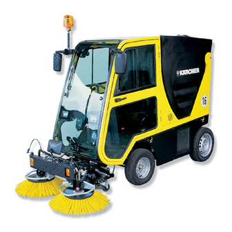
Unit Functions ICC 1 S D Equipment Features – Front view Cover, debris container Side brush, RH Debris container Head lamps Dual-circuit radiator Air exhaust, debris container (hydraulic fluid / engine coolant) Operator seat Support caster, vacuum intake Side brush, LH... -
Page 7: Side Brush View
ICC 1 S D Unit Functions Equipment Features – Sidebrush view Pressurized gas spring, side brush Stop screw, side brush bottom position Adjusting screws, side brush sweeping pattern Hydraulic motor, LF side brush LH side brush RH side brush Bumper... -
Page 8: Rear View
Unit Functions ICC 1 S D Equipment Features – Rear view Safety beacon Filler neck, fuel tank RH side brush Side cover panel Rear cover panel Water tank Filler neck, water tank... -
Page 9: Raised Debris Container View
ICC 1 S D Unit Functions Equipment Features – Raised debris container view Debris container Removable grille, dual-circuit radiator (hydraulic fluid / engine coolant) Air exhaust LH side brush Debris container cover Vacuum channel Water tank Rear cover panel... -
Page 10: Control Elements
Unit Functions ICC 1 S D Equipment Features – Control elements 6 7 8 9 10 KÄRCHER KÄRCHER Switch, four-way flashers (S12) Lever, Raise / Lower side brush and vacuum inlet (with brush speed control) Combination instrument (P1) Lever, Open / Close coarse debris flap... -
Page 11: Combination Instrument
ICC 1 S D Unit Functions Equipment Features – Combination instrument Indicator lights and displays Debris container raised Pre-glow cycle activated Excessive engine coolant temperature Spare Low charging current warning Low engine oil pressure warning Blocked air cleaner warning Headlamps ON... -
Page 12: Front Fuse Box
Unit Functions ICC 1 S D Equipment Features – Fuse box Fuses Relays Ignition switch Ignition switch Four-way flashers Fan, cabin heater Impeller fan brake Water pump Magnetic clutch Safety beacon Water pump Turn signals Fan, cabin heater Windshield wiper... -
Page 13: Control Console, Open View
ICC 1 S D Unit Functions Equipment Features – Control console, open view Control module, engine shut-off solenoid S14 Switch, safety beacon S15 Switch, windshield defroster fan Switch, cabin heater fan Switch, windshield wiper S16 Switch, working spotlights (option) S13 Combination switch... -
Page 14: Side Console, Open View
Unit Functions ICC 1 S D Equipment Features – Side console, open view Mounting thread for lever, Raise / Lower Hydraulic line, Lower brushes debris container Manual throttle Mounting thread for lever, Raise / Lower Control module, impeller fan brake (D3) -
Page 15: Engine Compartment, View From Left
ICC 1 S D Unit Functions Equipment Features – Engine compartment, view from left Magnetic clutch, vacuum impeller fan Fuel filter Filler neck, engine oil Engine Glow plug Tension roller, V-belt Injector nozzle V-belt Injection pump Magnetic brake, vacuum impeller fan... -
Page 16: Engine Compartment, View From Right
Unit Functions ICC 1 S D Equipment Features – Engine compartment, view from right Oil dip stick Coolant radiator electric fan Adjustment screw, V-belt tension Magnetic brake, vacuum impeller fan Exhaust manifold Starter Oil filler neck Alternator... -
Page 17: Engine Compartment, View Toward Rear
ICC 1 S D Unit Functions Equipment Features – Engine compartment, view toward rear RH limit switch, debris container (S10) LH limit switch, debris container (S11) Air cleaner Engine cover LH stop screw, debris container RH stop screw, debris container... -
Page 18: Fuel Tank
Unit Functions ICC 1 S D Equipment Features – Fuel tank Fuel level sensor Fuel filler neck Fuel tank... -
Page 19: Heater
ICC 1 S D Unit Functions Equipment Features – Heater Hot water supply hose Heat exchanger Warm water return hose Heater fan shroud... -
Page 20: Engine Compartment, View From Rear
Unit Functions ICC 1 S D Equipment Features – Engine compartment, view from rear... - Page 21 ICC 1 S D Unit Functions Equipment Features – Engine compartment, view from rear Relay, radiator fan (K9) Control module, pre-glow (D1) Fuse, radiator fan (F18) Fuse, glow plugs (F17) Splash water guard Hydraulic line, to hydraulic motor, RR wheel...
-
Page 22: Function Groups
Unit Functions ICC 1 S D Function Groups – Sweeping & Vacuum system Grille plate, deflection plate Vacuum duct Air exhaust Support casters Chain curtain Vacuum inlet Deflection plate Side brush Cover Spray nozzles Debris container Fresh water tank Engine... -
Page 23: Water System
ICC 1 S D Unit Functions Function Groups – Water system Water tank Metering valve, side brushes Tank fill level indicator in operator cab Shut-off valve Water filter Water pump * Effective with serial no. 10200, solenoid valve was replaced by non-return valve. - Page 24 Unit Functions ICC 1 S D Function Groups – Water system Shut-off valve Water filter Water pump Solenoid valve, water pump...
-
Page 25: Basic Settings And Service Procedures
ICC 1 S D Basic Settings and Service Procedures Engine – Fuel Cleaning fuel filter – Close fuel shut-off valve (1) by turning counter-clockwise one-quarter turn. – Loosen and unscrew knurled retaining ring (2), and remove fuel filter bowl (3) complete with contents. -
Page 26: Cooling
Basic Settings and Service Procedures ICC 1 S D Engine – Cooling Checking / topping up engine coolant Prior to checking coolant level, allow engine to cool. The proportion of antifreeze in the engine coolant must not exceed 50 percent. - Page 27 ICC 1 S D Basic Settings and Service Procedures Engine – Cooling Checking engine coolant temperature switch – Start engine. – If the "Engine Coolant Temperature" indicator light on the combination instrument illuminates also when the engine is cold, the connecting cable must be checked for a short-circuit against vehicle ground.
-
Page 28: Speed Adjustment
Basic Settings and Service Procedures ICC 1 S D Engine – Speed adjustments Adjusting idle speed Note: Engine speed may be checked with the use of a stroboscope, digital tachometer or vibration tachometer (refer to Special Tools). – Push manual throttle lever on right-hand side panel all the way in. -
Page 29: Engine Shut-Off Solenoid Valve
ICC 1 S D Basic Settings and Service Procedures Engine – Engine shut-off solenoid valve Engine shut-off solenoid valve As soon as the ignition switch (S1) is set to position "0" with the engine running, the engine shut-off control responds, and the solenoid valve (1) attracts. -
Page 30: Air Cleaner
Basic Settings and Service Procedures ICC 1 S D Engine – Air cleaner Checking / replacing air cleaner When the "Air Cleaner Warning" indicator light in the combination instrument illuminates, the air cleaner must be cleaned or its cartridge replaced. -
Page 31: Engine Oil
ICC 1 S D Basic Settings and Service Procedures Engine – Engine oil Checking engine oil level – After shutting off engine, allow at least five minutes to pass before checking oil level. – Oil level must be between "MIN" and "MAX"... -
Page 32: Drive Pump Belt
Basic Settings and Service Procedures ICC 1 S D Engine – Drive Pump belt Changing drive pump belt – Loosen and remove six mounting bolts (1). – Pull pumps (2) far enough toward the rear to separate coupling sleeve (3) from engine drive shaft (gap wide enough to allow drive belt to be passed through). -
Page 33: Sweeping Mechanism
ICC 1 S D Basic Settings and Service Procedures Sweeping Mechanism – Sweeping pattern Adjusting sweeping pattern – Check tire pressure (see Specifications). – Loosen clamp bolts (1). – Adjust lateral inclination of side brush (2) – Tighten clamp bolts (1). -
Page 34: Spray Nozzles
Basic Settings and Service Procedures ICC 1 S D Sweeping Mechanism – Spray nozzles Cleaning spray nozzles on side brush – Loosen union nut (1), and remove nozzle. – Blow out spray nozzle with pressurized air from front (2). Replace as required. -
Page 35: Vacuum Intake
ICC 1 S D Basic Settings and Service Procedures Sweeping Mechanism – Vacuum intake Coarse dirt flap Adjusting vacuum intake Sealing lip – Lower vacuum intake. Caster adjusting clamp bolt (4x) – Loosen clamp bolts (3) on both sides. Adjusting screw –... -
Page 36: Warning Buzzer, Debris Container
Basic Settings and Service Procedures ICC 1 S D Sweeping Mechanism – Warning buzzer, debris container Adjusting warning buzzer switch – Pull knobs off control levers (2, 3). – Remove panel mounting screws (4). – Detach Bowden cable at injection pump (see page 28). -
Page 37: Debris Container
ICC 1 S D Basic Settings and Service Procedures Sweeping Mechanism – Debris container Debris container Removing debris container Container swivel bolt (2x) – Raise debris container until level, and shut off engine. Lifting cylinder retaining bolt (2x) – Attach rope slings to crane hook and debris LH side panel container as shown. -
Page 38: Running Gear
Basic Settings and Service Procedures ICC 1 S D Running Gear – Grease fittings Lubricating steering knuckles – Lubricate grease fittings on both steering knuckles (arrow) on front axle with 3-5 shots from grease gun. Lubricating steering knuckle Lubricating axle mounting –... -
Page 39: Brake
ICC 1 S D Basic Settings and Service Procedures Running Gear – Brake Adjusting screw Adjusting brakes Drum brake Note: Brake lever Parking barke and operating brake act on Lock nut both front wheels via brake cables (drum brake). Braking action on rear wheels is by hydraulics only. - Page 40 Basic Settings and Service Procedures ICC 1 S D Running Gear – Brake (view from below) Floor panel Replacing stop light switch Actuating spring, stop light switch – Remove actuating spring from eyelet (2). Protective cap, stop light switch (S 19) –...
-
Page 41: Wheel Change / Steering Wheel
ICC 1 S D Basic Settings and Service Procedures Running Gear – Wheel change / Steering wheel Changing rear wheel – Secure unit to prevent rolling, and loosen wheel bolts. – Insert round steel bar (20 mm dia.) into rear jacking eye. -
Page 42: Toe-In Adjustment
Basic Settings and Service Procedures ICC 1 S D Running Gear – Toe-in adjustment Adjusting toe-in – Set steering wheel for straight-ahead travel. – Hook measuring tape into one of the tire tread grooves. Hooking measuring tape into tread groove –... -
Page 43: Shock Absorber
ICC 1 S D Basic Settings and Service Procedures Running Gear – Shock absorber Upper mounting bolt Replacing shock absorber Loading ramp – Move unit with one wheel onto loading ramp (2) of approx. 150 mm height. Lower mounting bolt –... -
Page 44: Towing And Transporting
Basic Settings and Service Procedures ICC 1 S D Running Gear – Towing and transport Important: The unit may be towed only with bypass valve open. Towing with closed bypass valve will damage hydraulic drive components. Towing speed must not exceed walking speed, and towed distance must be less than 250 m. -
Page 45: Hydraulic System
ICC 1 S D Basic Settings and Service Procedures Hydraulic System – Hydraulic fluid Note: When carrying out procedures on the hydraulic system, care must be taken to maintain extreme cleanliness throughout. Even minor contaminations may cause component damage or complete system failure. -
Page 46: Hydraulic Fluid Filter
Basic Settings and Service Procedures ICC 1 S D Hydraulic System – Hydraulic fluid filter Replacing hydraulic fluid filter Replacement of the hydraulic fluid filter is required when indication of pressure gauge is in red range. Note: Engine must be shut off before the filter can be changed. -
Page 47: Emergency Pump (Option)
ICC 1 S D Basic Settings and Service Procedures Hydraulic System – Emergency pump (option) Lever, emergency pump Raise / Lower debris container To carry out repairs, the emergency pump (1) Lever, Raise / Lower debris container can be used to raise the debris container without the need to start the engine. -
Page 48: Drive Pedal
Basic Settings and Service Procedures ICC 1 S D Hydraulic System – Drive pedal Setting NEUTRAL on hydraulic drive pump If the unit creeps forward or backward without drive pedals being actuated, setting the NEUTRAL position on the hydraulic drive pump will be required. -
Page 49: Checking Working Pressures
ICC 1 S D Basic Settings and Service Procedures Hydraulic System – Checking working pressures Connecting union on testing setup Checking drive hydraulic pressure T-joint – Secure unit by setting parking brake. Connecting union on bypass line – Unscrew connecting union (3) from T-joint (2). - Page 50 Basic Settings and Service Procedures ICC 1 S D Hydraulic System – Checking working pressures (continued) Pressure-side connection Checking hydraulic pressure for side brushes and debris container T-joint – Unscrew pressure line to control block (3) Pressure line to control block, side from pressure-side connection (1).
-
Page 51: Pressure Relief Valve
ICC 1 S D Basic Settings and Service Procedures Hydraulic System – Pressure relief valve Adjusting pressure relief valve The pressure relief valve is used to adjust the working pressure for functions such as "Raise / Lower Debris Container" and raising / lowering side brushes and vacuum intake. -
Page 52: Pumps
Basic Settings and Service Procedures ICC 1 S D Hydraulic System – Pumps Removing hydraulic pumps The hydraulic pumps powering the working hydraulics and steering are mounted beneath the battery (3) as an extension of the engine drive shaft. –... -
Page 53: Impeller Fan
ICC 1 S D Basic Settings and Service Procedures Impeller fan Vacuum hose Changing impeller fan Hose clamp – Raise front of unit approx. 200 mm or drive on inclined ramp. Front axle carrier – Raise debris container to highest position and Front wheel secure. - Page 54 Basic Settings and Service Procedures ICC 1 S D Impeller fan (continued) Changing impeller fan (continued) Retaining bolt Impeller fan – Deflect steering all the way to the left. – Remove hydraulic lines from steering cylinder. – Detach accelerator cable at side panel (see page 36).
-
Page 55: Adjusting Magnetic Brake
ICC 1 S D Basic Settings and Service Procedures Impeller fan Air gap Adjusting magnetic brake Brake lining To ensure proper functioning of the magnetic brake, the air gap (1) between brake lining (2) Shim (7.343-026) and drive plate must be adjusted. -
Page 56: Troubleshooting
Troubleshooting ICC 1 S D Troubleshooting Problem Remedy Starter fails to turn engine – Check / replace fuse F1 – Check ground connection between engine and chassis – Check battery G1 (voltage, electrolyte level & density) – Check / replace ignition switch S1 –... - Page 57 ICC 1 S D Troubleshooting Troubleshooting Problem Remedy Engine cannot be shut off – Check engine shutoff control module D2 – Check / replace ignition switch S1 – Check / replace engine shutoff solenoid valve Y1 No fuel tank level indication –...
-
Page 58: Circuit Diagram
Circuit Diagram ICC 1 S D Circuit diagram 0.088-215, page 1... - Page 59 Designation Installed location Designation Installed location Cab control console Ignition switch Level sensor Fuel tank Oil pressure switch Engine compartment Module, preglow Rear fuse box Temperature switch, Engine compartment Module, engine shutoff Control console engine coolant Fuse, ignition switch Front fuse box Vacuum switch, air Air cleaner housing cleaner...
- Page 60 Circuit Diagram ICC 1 S D Circuit diagram 0.088-215, page 2...
- Page 61 Designation Installed location Designation Installed location Cab, under seat Control, impeller fan brake Side console Switch, folding seat Switch, heater fan Control console LH working spotlight Switch, water pump Control console RH working spotlight Switch, magnetic clutch Side console Fuse, impeller fan brake Front fuse box LH limit switch, debris Water tank, raise debris...
- Page 62 Circuit Diagram ICC 1 S D Circuit diagram 0.088-215, page 3...
- Page 63 Designation Installed Location Designation Installed location Horn Front bumper Relay, turn signals Front fuse box Headlamp, L Windshield Switch, four-way flashers Instrument panel Headlamp, R Windshield Combination switch Instrument panel Position light, LF Front bumper Switch, stop lights Brake pedal assy. Position light, LR Windshield Plug connector...
-
Page 64: Circuit Diagram - Search List
Designation Installed location Designation Installed location B1 Level sensor, fuel Fuel tank F14 Fuse, windshield defroster Front fuse box B2 Horn Front bumper F15 Fuse, stop lights Front fuse box D1 Control module, preglow Rear fuse box F16 Fuse, headlamps Front fuse box D2 Control module, engine shutoff Control console... - Page 65 Designation Installed location C/D Designation Installed location M1 Starter Engine compart. P1 Combination instrument Instrument panel M2 Water pump Engine compart. V1 Diode On connecting wire V2 Diode On connecting wire M3 Heater fan, cab Cab rear wall V3 Diode On connecting wire M4 Windshield wiper V4 Diode...
-
Page 66: Hydraulic Block Diagram
Hydraulic Block Diagram ICC 1 S D Hydraulic block diagram 0.088-258... -
Page 67: Hydraulic Block Diagram
ICC 1 S D Hydraulic Block Diagram Hydraulic block diagram 0.088-258 Hydraulic fluid tank Hydraulic fluid filter, return line Oil cooler Combustion engine Assembly, drive components Precharge valve Precharge pump Hydraulic pump, drive Non-return valve Control valve, low acceleration Bypass valve Hydraulic motor, R &... -
Page 68: Hydraulic Line Diagram
Hydraulic Line Diagram ICC 1 S D Hydraulic line diagram 2.706-010... -
Page 69: Hydraulic Line Diagram
ICC 1 S D Hydraulic Line Diagram Hydraulic line diagram 2.706-010 Hydraulic motor, LH side brush Steering valve Hydraulic motor, RH side brush Hydraulic cylinder, steering Valve block, steering Control block, side console Hydraulic pump, steering Hydraulic pump, side brushes and... -
Page 70: Specifications
Specifications ICC 1 S D Specifications Diesel engine................... Type KUBOTA D722 Operating speed ................RPM 2650 – 2800 Idle speed ..................RPM 800 – 900 Oil type, diesel engine ..............Type 10 W 40 Oil capacity, diesel engine ............... l 3.8 Sound noise level ................ -
Page 71: Special Tools
ICC 1 S D Specifications Special tools Testing equipment ................... 2.639-387 Tachometer ..................... 6.491-361 Magnetic field tester ................6.803-003 Assembly torque ratings Rear wheels .................... 100 Nm Front wheels.................... 90 Nm...