Table of Contents
Advertisement
Advertisement
Table of Contents
Troubleshooting

Related Manuals for Tecumseh V-twin


Summary of Contents for Tecumseh V-twin
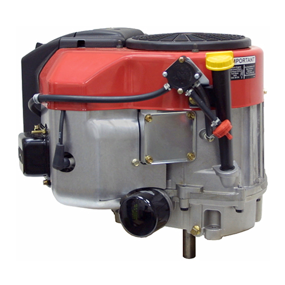
- Page 1 TECUMSEH V-TWIN ENGINE Small Engine Parts...
- Page 2 All rights reserved. No part of this book may be reproduced or transmitted, in any form or by any means, electronic or mechanical, including photocopying, recording or by any information storage and retrieval system, without permission in writing from Tecumseh Products Company Training Department Manager.
-
Page 3: Table Of Contents
TABLE OF CONTENTS (by subject) GENERAL INFORMATION Page Engine Identification ....................1-1 Interpretation of Engine Identification ..............1-1 Short Blocks ......................1-2 Fuels ........................1-2 Engine Oil ........................ 1-3 Basic Tune-Up Procedure ..................1-4 Storage ........................1-4 AIR CLEANERS General Information ....................2-1 Operation ......................... - Page 4 TABLE OF CONTENTS (continued) Page Speed Controls and Linkage ................... 4-3 Synchronizing the Carburetors ................4-4 Choke Synchronization .................... 4-5 ELECTRICAL SYSTEMS General Information ....................5-1 Operation ......................... 5-1 Converting Alternating Current to Direct Current ............. 5-2 Components Battery ......................5-2 Wiring ......................
- Page 5 TABLE OF CONTENTS (continued) Page INTERNAL ENGINE AND DISASSEMBLY General Information ....................7-1 Lubrication Systems ....................7-1 Disassembly Procedure ................... 7-1 Disassembly of Cylinder Heads ................7-4 Valves ......................7-5 Valve Guides ....................7-5 Valve Springs ....................7-6 Push Rods ....................... 7-6 Valve Seats ......................
-
Page 6: General Information
ENGINE IDENTIFICATION The group of numbers following the model number is the specification number. The last three numbers Tecumseh engine model, specification, and date of indicate a variation to the basic engine specification. manufacture (D.O.M.) are located on decals attached to (Illust. -
Page 7: Short Blocks
Time may be extended with the use of a fuel stabilizer like TECUMSEH, part number 730245. NOTE: To maintain the best possible emission See “STORAGE” instructions in this Manual, Operators performance, use only Genuine Tecumseh Parts. -
Page 8: Engine Oil
(Illust. 1-7) The oil filter if equipped, can be removed Be sure original container is marked: A.P.I. service “SF” with a commercially available filter wrench. thru “SJ” or “CD”. TECUMSEH RECOMMENDS USING ONE OF THE FOLLOWING FOUR CYCLE OILS THAT ARE SPECIALLY FORMULATED TECUMSEH SPECIFICATIONS. -
Page 9: Basic Tune-Up Procedure
An acceptable alternative to removing all gasoline, is by thread. Tighten the spark plug to 21 foot pounds adding Tecumseh fuel stabilizer, part number 730245, (28 Nm) of torque. If a torque wrench is not to the gasoline. Fuel stabilizer is added to the fuel tank available, turn the spark plug in as far as possible or storage container. -
Page 10: Air Cleaners
CHAPTER 2. AIR CLEANERS GENERAL INFORMATION COMPONENTS The air cleaner is the device used to eliminate dust and The cover holds the poly pre-cleaner and clamps the dirt from the air supply. Filtered air is necessary to assure paper filter in place, creating a dirt tight seal. The cover that abrasive particles are removed before entering the also prevents large debris from entering the filter body. -
Page 11: Service
NOTE: Never run the engine without the complete air cleaner assembly installed on the engine. Always replace the filter element with a Tecumseh original replacement part to maintain proper filtration, emissions compliance and long engine life. Disassembly Procedure 1. -
Page 12: Carburetors And Fuel Systems
CHAPTER 3. CARBURETORS AND FUEL SYSTEMS GENERAL INFORMATION OPERATIONAL CIRCUITS SERIES 7 CARBURETOR The TVT engine uses two series seven (7) float type carburetors. This carburetor uses a choke enrichment system to provide easy cold engine starting. To comply SERIES 7 IDLE PROGRESSION HOLES with emission standards, the carburetor idle and high- speed fuel mixtures are non-adjustable. - Page 13 Idle Mixing Well: The idle mixing well of the carburetor Governed Idle Circuit: The TVT series engine uses a contains a series of metering holes. These metering holes governed idle system. In the low speed throttle position, are the primary and secondary idle circuit as well as the engine speed is being maintained by the governor NOT idle air bleed hole.
-
Page 14: Testing
Main Nozzle Air Bleed: Air is bled into the main nozzle TESTING through the main nozzle air bleed passage located in 1. Should repeated efforts to start the engine using the the 6 o’clock position of the carburetor’s choke end. (Illust. procedure listed in the operator’s manual fail, check 3-6) This passage allows air to mix with the fuel traveling for spark by removing the high-tension lead. - Page 15 Turn the engine over very slowly by hand to remove replacement. excess gasoline from the engine cylinder. 7. Compression Test Most Tecumseh engines include CAUTION: KEEP ALL COMBUSTIVE SOURCES a compression relief system. These systems make AWAY. AVOID THE SPRAY FROM THE SPARK publishing compression values impractical.
-
Page 16: Carburetor Disassembly Procedure
CARBURETOR DISASSEMBLY 2. Remove the main nozzle (Emulsion) tube, “O” ring, and spring located in the center leg of the float bowl. PROCEDURE (Illust. 3-10) Before performing any carburetor service check the throttle/choke control(s) for proper adjustments. Make SPRING sure the unit is reaching full choke shutter position on MAIN NOZZLE (EMULSION TUBE) both carburetors. - Page 17 5. Remove the inlet needle seat using a No. 4 crochet NOTE: Before removing the main carburetor body, hook or a paper clip with a 3/32" (2.38 mm) hook mark or sketch the choke and throttle linkage end. Push the hook through the hole in the center of connection points.
-
Page 18: Inspection
INSPECTION CARBURETOR RE-ASSEMBLY WELCH PLUGS After careful disassembly of the carburetor, clean the carburetor body and float bowl with solvent, or spray To install a new welch plug, secure the carburetor in a carburetor cleaner. Wearing eye protection, use vise equipped with protective jaws. Place the welch plug compressed air and soft tag wire to clean internal into the mixing well pocket with the raised portion up. -
Page 19: Choke Shaft And Plate
FUEL BOWL ASSEMBLY CHOKE SHAFT AND PLATE Inlet Needle & Seat Install the choke return spring on the choke shaft with When servicing the fuel bowl assembly, a new needle the squared end up and hooked into the notch on the and seat should always be installed to reduce the arm. -
Page 20: Impulse Fuel Pumps
1 - Body, Impulse Final Checks 2 - Body, Pump 3 - Cover, Pump Test the inlet needle and seat sealing using Tecumseh 4 - Bearing, Spring service kit 670340 or a similar pop-off tester. To test the 5 - *Valve, Check (2) -
Page 21: Impulse Fuel Pump Service
Fuel Pump Testing: The maximum lift is 24 inches 4. Clean the body parts with solvent and blow out all (610 mm). A fuel pump may be tested with our leak test passages using compressed air. kit part number 670340 or a commercially available low pressure gauge. -
Page 22: Governors And Linkage
CHAPTER 4. GOVERNORS AND LINKAGE GENERAL INFORMATION ENGINE SPEED ADJUSTMENTS The TVT engine is equipped with an internal mechanical Before attempting to set the governed high or low RPM governor. The governor’s function is to maintain a R.P.M. speeds, locate the recommended RPM setting according setting when engine loads are added or taken away. -
Page 23: Engine Overspeed
ENGINE OVERSPEED 2. If the engine R.P.M. stabilizes, re-adjust the governor setting. Check the governor shaft, linkage, bushing 1. If the engine runs wide open (faster than normal), clips and spring for binding, wear, or improper shut the engine off immediately. hookup. -
Page 24: Governor Gear And Shaft Service
GOVERNOR GEAR AND SHAFT SERVICE SPEED CONTROLS AND LINKAGE After the cylinder cover is removed from the engine, the The TVT series engine offers the adaptability of throttle governor spool, gear, and governor shaft can be cable connection from either side of the engine. Either removed. -
Page 25: Synchronizing The Carburetors
SYNCHRONIZING THE CARBURETORS 3. Manually rotate the throttle shaft on the number #2 carburetor to the idle position. Next back out the idle The TVT series uses twin carburetors, which MUST be R.P.M. adjustment screw until it no longer contacts synchronized if the linkage or carburetor body has been the throttle plate tang. -
Page 26: Choke Synchronization
Set the governed idle and top no-load RPM. The correct RPM settings can be located on microfiche card #30 or the computer parts look-up systems. The use of a vibra-tach Tecumseh part #670156 or a digital engine tachometer part #670341 will aid in this procedure. -
Page 27: Electrical Systems
CHAPTER 5. ELECTRICAL SYSTEMS GENERAL INFORMATION OPERATION The electrical system consists of three main elements: Although most equipment has an electrical system that a battery, a starting circuit, and a charging circuit. The consists of three main elements, (battery, starting circuit, battery is part of both the starting and charging circuit. -
Page 28: Converting Alternating Current To Direct Current
(Illust. 5-4) COMPONENTS BATTERY The batteries used in conjunction with Tecumseh engines are 12 volt lead acid or “maintenance free” style. The chemical energy produced by the dissimilar metals of THE LARGER THE NUMBER THE SMALLER THE WIRE the battery plates provides an electrical potential that is used to power the electric starter or unit accessories. -
Page 29: Electrical Terms
Before going into extensive diagnostics, be sure to #18 or lower gauge number. perform the more basic checks first, such as: Tecumseh Products Company’s standard wiring color 1. Battery not fully charged or defective. codes effective August, 1992 are as follows: 2. -
Page 30: Charging Circuit
Place the solderless number from the engine. Consult a Tecumseh dealer or connector from the new diode onto the exposed 1/4” (6.35 a parts manual to correctly identify the charging system. -
Page 31: Checking The System
CHECKING THE SYSTEM: To check the system, 16 AMP ALTERNATOR SYSTEM WITH disconnect the plug and measure the D.C. voltage at the EXTERNAL REGULATOR red wire terminal. Measure the A.C. voltage at the yellow wire terminal. With the engine running, the minimum CAUTION: FOLLOW ALL SAFETY PRE- values should be: CAUTIONS WHEN TESTING FOR A.C. -
Page 32: Troubleshooting Electrical Charging Circuit Flow Chart
TROUBLESHOOTING ELECTRICAL CHARGING CIRCUIT FLOW CHART Identify the charging system used by model and specification number or visually checking the electrical plug. Consult the Technician's Handbook or electrical troubleshooting booklet for test procedure for the charging system used. Test for either AC or DC voltage as directed at the proper engine RPM. -
Page 33: Voltage Regulators
FUEL SHUT-DOWN SOLENOIDS VOLTAGE REGULATORS If the engine is running, the solenoid(s) can be checked If a known good or load tested battery fails to maintain a by removing the electrical plug-in at the base of the charge, the charging system and the regulator can be solenoid. -
Page 34: Starting Circuit
STARTING CIRCUIT 3. Check wiring, connections, circuit breakers, fuses, ignition or starter switch, safety switches, and After all of the safety interlock switches have been solenoid for continuity using an ohmmeter or activated, the starter switch closes the starting circuit. continuity light. -
Page 35: Troubleshooting Electrical Starter Circuit Flow Chart
TROUBLESHOOTING ELECTRICAL STARTER CIRCUIT FLOW CHART Starter turns at Intermittent Starter will not low rpms or stalls starter operation. turn. under load. Is there power at the power source? Repair or Is power supplied to the replace power starter terminal? source. -
Page 36: Electric Starter Service
ELECTRIC STARTER SERVICE 3. Slide off the spring retainer, anti-drift spring, gear, and drive nut. (Illust. 5-14) This section covers the service procedures for 12 volt electric starters. For diagnosis of the starting circuit see “Electrical Starter Troubleshooting” in this chapter. NOTE: Internal service may not be allowed under various country regulations. -
Page 37: Inspection And Repair
5. Remove the through bolts holding the commutator 7. Remove the armature. end cap assembly on. (Illust. 5-16) 8. Inspect and replace as necessary, see the section “Inspection and Repair” later in this chapter. Use the reverse procedure for assembly. For ease of assembly, place the armature into the brush end of the frame first. -
Page 38: Brush Holder
4. Use a continuity tester to make certain no continuity BRUSH HOLDER exists between the commutator copper and the iron Install finishing nails into a block of wood according to of the armature. Rotate the armature and check out the following diagram. (Illust. 5-21) all of the commutator bars. -
Page 39: General Information
CHAPTER 6. IGNITION GENERAL INFORMATION COMPONENTS The solid state module (CDI) is a complete unit that The ignition system consists of flywheel magnets, flywheel key, charge coil, capacitor, resistor, a silicon includes the laminations, SCR, capacitor, resistor, pulse controlled rectifier, pulse transformer, trigger coil, high transformer, charge coil, trigger coil, and spark plug high tension lead, and a spark plug. -
Page 40: Testing Procedure
TESTING PROCEDURE 5. Check the flywheel magnets for the proper strength. Hold a screwdriver at the extreme end of the handle with the blade down, move the blade to within 3/4 1. Check for spark using an ignition tester and following inch (19.05 mm) of the magnets. -
Page 41: Service
SERVICE CONDITIONS CAUSING FREQUENT SPARK PLUG FOULING SPARK PLUG SERVICE 1. Air cleaner is restricted. (Replace) 2. Partially closed choke shutter. (Check operation) Spark plugs should be removed, inspected and adjusted periodically. Replace the spark plugs every 100 hours or 3. -
Page 42: Service Tips
Timing on a solid state module is not adjustable. The SERVICE TIPS proper air gap of .0125" (.3175 mm) using Tecumseh part 670297 and the correct flywheel key in good DO NOT: condition are the only timing variables. Set the gap by •... -
Page 43: Internal Engine And Disassembly
CHAPTER 7. INTERNAL ENGINE AND DISASSEMBLY GENERAL INFORMATION DISASSEMBLY PROCEDURE This chapter covers the cylinder block, piston and rod 1. Disconnect the high-tension leads from the spark assemblies, cylinder heads, crankshaft, camshaft, valve plugs. Remove the spark plugs. Evaluate each of train, breather, cylinder cover, flywheel, and lubrication the spark plug(s) condition, for tips on areas systems. - Page 44 11. Remove the flywheel nut, washer, and fan. Use part 14. Remove the governor spring. Separate the link 670305 strap wrench to hold the flywheel from connector bushing clip from the throttle link at the turning. (Illust. 7-3) Thread a flywheel knock-off tool governor lever.
- Page 45 17. Remove the crankcase breather cover plate, reed 19. Remove the camshaft and lifters. It is not necessary valve and limit plate. NOTE: The reed valve is to mark the lifters as to their original location. notched. This notch must face the cylinder head side of the engine for proper function.
-
Page 46: Disassembly Of Cylinder Heads
DISASSEMBLY OF CYLINDER HEADS Disassembly of the cylinder heads is best done one at a time to prevent mixing valves from one head to the other. Before beginning service of the cylinder head check for Place a shop towel or other similar soft product under warpage by placing the head on a precision flat surface. -
Page 47: Valves
VALVES If the valves have been checked and are in a usable condition, the valve face should be ground at a 45 degree angle. If after grinding the valve face the top margin is Specification English Metric less than .03125 (.794 mm), the valve should be Min Valve Stem Dia. -
Page 48: Valve Springs
VALVE SPRINGS PUSH RODS The push rods should be checked for straightness and the ends for wear. If the push rod ends are worn or Specification English Std. Metric damaged, inspect the corresponding rocker arm socket or valve lifter for wear. Replace if necessary. Valve Spring 1.935 - 1.995 49.15 - 50.67... -
Page 49: Internal Engine Component Inspection
Third, use the 46 degree cutter to cut the seat to a width A rigid type hone is recommended to “true” any minor of .078125 (1.191 mm) (Illust. 7-20). Check the contact cylinder irregularities. If the cylinder bore is worn, scored area of a new or reconditioned valve face on a finished or out of round more than .005"... -
Page 50: Pistons
PISTONS, RINGS, AND CONNECTING If the cylinder bore needs re-sizing, an oversize piston will be necessary. Oversize pistons are identified by the RODS decimal oversize value imprinted on the top of the piston. (Illust. 7-24) PISTON Specification English Std. Metric Piston Diameter 3.1220 79.2988... -
Page 51: Rings
Piston Ring .002-.005 Top .051-.127 Top 2. Use a ring expander (Tecumseh tool part number Side Clearance .001-.004 Center .025-.102 Center 670117) to replace the piston rings. Do not spread .001-.004 Bottom .025-.102 Bottom... -
Page 52: Connecting Rods
CONNECTING RODS Specifications English Std. Metric Connecting Rod Journal 1.6223 41.206 Diameter 1.6228 41.219 Connecting rod Diameter .6251 15.878 Piston Pin End .6256 15.890 Connecting Rod Thrust Face .988 25.095 .996 25.299 Connecting Rod Thrust Clearance .006 .1510 With Both Rods On Crankshaft .027 .6858 The TVT engine is designed with offset piston pins (not... -
Page 53: Crankshafts And Camshafts
3. Position the connecting rod match marks and the arrow on the piston assembly to be on the same side, and assemble. (Illust. 7-31) ARROW MARK Þ Þ ARROW AND MATCH MARKS MATCH MARKS 7-31 4. When installing the piston and rod assembly in the engine the match marks must align and face out. -
Page 54: Mechanical Compression Release
CAUTION: NEVER ATTEMPT TO STRAIGHTEN A MECHANICAL COMPRESSION RELEASE BENT CRANKSHAFT. The Mechanical Compression Release (MCR) incorporates pins located in the camshaft. The pins Inspect the crankshaft oil galleys for blockage or extend above the exhaust cam lobes, lifting the valve obstruction. -
Page 55: Valve Lifters
VALVE LIFTERS CYLINDER COVER Visually check the lifter for wear on the cam contact surface, the cylinder contact surface and push rod contact Specification English Std. Metric surface. If any damage is noted replace the lifters. (Illust. 7-34). Main Bearing Diameter 1.625 41.313 1.627... -
Page 56: Engine Assembly
CHAPTER 8. ENGINE ASSEMBLY ENGINE ASSEMBLY 6. Assemble the compression release components to the camshaft. Install spring end “A” through the The following procedures apply to most engine specs. weight from the shaft side. Wrap spring end “B” over Actual procedure may vary. the rivet head as shown (Illust. - Page 57 8. Install the oil pump shaft into the flange cover from 10. Use seal protector 670330 to install the mounting the bottom up. The long end of the shaft inserts into flange with the governor gear assembly installed to the cover. (Illust. 8-4) the crankcase.
- Page 58 16. Insert the push rods in the lifter sockets with the 23. Install the intake pipe, carburetors and governor longer steel end towards the rocker arms. Install the linkage. Check the governor and speed control hook- rocker arms (socket end toward the push rod) and up and adjustment - see Chapter 4 Governors and guide plate (with the arms facing up) onto the cylinder Linkage.
-
Page 59: Engine Knocks
CHAPTER 9. TROUBLESHOOTING & TESTING ENGINE KNOCKS 7. Remove the cylinder head to check for excessive carbon buildup or a leaking head gasket(s). Replace 1. Check the crankshaft coupler or pulley for loose fit, head gasket(s). loose bolts or crankshaft key damage. Remove, inspect, and replace as necessary. -
Page 60: Engine Vibrates Excessively
ENGINE VIBRATES EXCESSIVELY 4. Check for excessive engine R.P.M. Use a vibra-tach or other tachometer to adjust to the specified R.P.M. 1. Detach and ground the high-tension leads from the setting found on microfiche card # 30 or the computer spark plugs. -
Page 61: Engine Specifications
CHAPTER 10. ENGINE SPECIFICATIONS TVT 691 ENGINE SPECIFICATIONS English Std. Metric Displacement 42.18 cubic inches 691cc Stroke 2.75 69.85 Bore 3.126 79.4004 3.125 79.375 PISTONS Piston Diameter 3.1220 79.2988 3.1235 79.3369 Piston Pin Diameter .6248 15.870 Piston Pin Bore Diameter .6251 15.878 .6257... - Page 62 TVT 691 ENGINE SPECIFICATIONS (CONTINUED) English Std. Metric CRANKSHAFT Crankshaft End Play .0053 .1346 .025 .6350 Crankshaft Connecting Rod Journal Thrust Width 1.998 50.749 2.003 50.876 Crankshaft Connecting Rod Journal Diameter 1.6223 41.206 1.6228 41.219 Main Bearing Journal Dia. Flywheel and PTO End 1.6245 41.263 1.625...
-
Page 63: Torque Specifications
TORQUE SPECIFICATIONS Torque specifications below 10-ft lbs. will be listed in inch lbs. only to encourage the use of a inch lbs. torque wrench. In. lbs. Ft. lbs. Cylinder Head Bolts Connecting Rod Bolts 17.5 Cylinder Cover (sump) Flywheel Nut Spark Plug Ignition Module to Stud —... -
Page 64: Service Tool List
(Neway 612 Gizmatic) Torx E-6 Socket 670257 Cylinder Hone (Flex) 670360 Torx E-8 Socket 670307 * See Tecumseh Form #694862 for Complete Tool Kit List ** Neway LG2000 or 102 kits can be upgraded by calling Neway direct: 1-800-248-3889 10-4 Tecumseh Parts...