Table of Contents
Advertisement
Advertisement
Table of Contents

Related Manuals for American Standard ULN 75-76


Summary of Contents for American Standard ULN 75-76
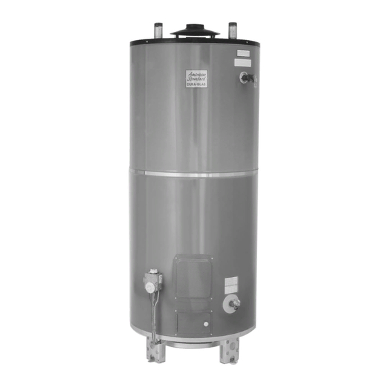
- Page 1 MODELS: ULN 75-76, 100-83, 100-76 ULN 75-76R, 100-83R, 100-76R RU 75-76, 100-83, 100-76 operating, installation and service manual Commercial Gas Water Heater 561 New York Drive, Pomona • CA 91768 1(800) 900-9063 • (909) 392-0230 • Fax (909) 392-7302 REV. 01 April 2013...
- Page 2 OPERATING, INSTALLATION AND SERVICE MANUAL DANGER STORAGE TYPE GAS WATER HEATER WITH FLUE DAMPER AND ELECTRIC IGNITION SYSTEM WITHOUT FAN MOTOR Keep flammable products: 1. far away from heater, REQUIRES 120V A.C. POWER SUPPLY 2. in approved containers, 3. tightly closed and 4.
-
Page 3: Table Of Contents
WARNING WARNING TABLE OF CONTENTS Fire Hazard Read and understand instruction manual and safety messages before installing, operating or servicing this water heater For continued protection against risk of fire: WARNINGS Failure to follow instructions and safety messages . Do not install water heater on carpeted floor. WARRANTY LIMITATIONS, CONSUMER RESPONSABILITIES, PRESSUHRE BUILD-UP, could result in death or serious injury. - Page 4 WARRANTY LIMITATIONS THE MANUFACTURER OF THIS WATER HEATER WILL NOT BE RESPONSIBLE FOR TANK FAILURES OR WATER HEATER FAILURES RESULTING FROM ANY OF THE FOLLOWING CONDITIONS AND MAY AT IT’S DISCRETIONS VOID THE WATER HEATER WARRANTY WHEN THESE CONDITIONS RESULT IN PREMATURE FAILURES OF THE TANK OR COMPONENTS 1.
- Page 5 SUBJECT TO PHYSICAL DAMAGE BY MOVING VEHICLES OR AREA conjunction with this water heater. FLOODING. ULN 75-76-AS, 75-76 AS-R-6, 75-76-AS-R-12 This water heater has been equipped for use with one type of gas only. Compare the information provided on the rating plate affixed to the front of the water heater, making sure that the gas stated on the rating plate is the same as the gas to be used.
-
Page 6: Drafthood Location & Flue Damper Installation, Venting
THE WARRANTY ON THIS WATER HEATER DOES NOT COVER DAMAGE CAUSED FROM OPERATION IN A CORROSIVE ATMOSPHERE. ULN 75-76-AS, ULN 75-76-AS-R-6, ULN 75-76-AS-R-12 ULN 100-76-AS, ULN 100-76-AS-R-6, ULN 100-76-AS-R-12 Water Damage/Drain Pan- The water heater should be located in an area where leakage of the tank or connections 4 in will not result in damage to the area adjacent to the water heater or to lower floors of the structure. -
Page 7: Water Connections
GAS PIPING Draft Diverter- This water heater has been shipped with a draft diverter for which it was designed with reference to the horizontal and vertical planes. If removed, the draft diverter shall be replaced in the same position and secured to the jacket top by the screws with which it was installed. Use clean black iron pipe or equivalent material approved by local codes and ordinances for gas piping. -
Page 8: Typical Installation
SINGLE COMMERCIAL GAS MODEL TYPICAL INSTALLATION TOP CONNECTIONS WITH RETURN CIRCULATION Hot Water Service Sheet Metal Screws Vent Vent Connector STORAGE TANK Min 1/4” in rise per linear feet Shut off valve Bleed valve Return Line from service (When Used) T &... -
Page 9: All Air From Outdoors
AIR SUPPLY ALL AIR FROM OUTDOORS Important air for combustion and ventilation must not come from a corrosive atmosphere. Any failure due to corrosive elements in the atmosphere The confined space shall be provided with two permanent openings, one commencing within 12 inches of the top and one commencing within 12 is excluded from warranty coverage. -
Page 10: Discharge Of Purged Gases, Venting
NOTE: If the equipment room is located against an outside wall and the air openings communicate directly with the outdoors, each opening shall have a free area After completing all gas connections, check each gas connection and fitting for leaks. Use a soap and water solution or a commercial leak detector of not less than one square inch per 4,000 BTU per fluid. -
Page 11: Temperature And Pressure Relief Valve
INSTALLATION (Using Top Connect Only) TEMPERATURE AND PRESSURE RELIEF VALVE For protection against excessive pressures and/or temperatures, a temperature and pressure relief valve must be installed in the opening marked "temperature and pressure relief valve". A design certified by a nationally recognized testing laboratory that maintains periodic inspection of production of listed equipment or materials, as meeting the requirements for Relief Valves and Automatic Gas Shut-off devices for Hot Water Supply Systems, ANSI Z21 .22. -
Page 12: Installation Checklist
ELECTRICAL INSTALLATION CHECK LIST Before putting burner in operation 120 VAC LESS THAN 5 AMPS This is presented for ease of reference. It is not comprehensive. All instructions and warnings must be read and adhered to When installed, this appliance must be electrically grounded in accordance with local codes or in the abscence of local codes, with the National Electrical Code, ANSI/NFPA NO. -
Page 13: Wiring Diagram
DAMPER DAMPER OPERATION SEQUENCE WIRING DIAGRAM POTENTIOMETER VOLTAGE 24 AC DISCONNECT UPPER LOWER W R Y SERVICE SWITCH LEGEND 24V (GND) DM Damper Motor RELAY F Fuse TH Thermostat ES Endswitch CM Control Module R Relay Coil IGNITION CONTROL R1 N/C Relay Contact HONEYWELL S8600C R2 N/O Relay Contact SS1 N/C Safety Switch Contact... - Page 14 NATURAL GAS MODELS DANGER IF YOU SMELL GAS: 1.- Open windows. DO NOT STORE OR USE ANY COMBUSTIBLE MATERIALS OR LIQUIDS, SUCH AS GASOLINE, PAINT THINNERS OR OTHER 2.- Get all people out of the building. FLAMMABLE VAPORS NEAR ANY GAS BURNING APPLIANCES. VAPORS MAY BE IGNITED BY THE PILOT OR MAIN BURNER 3.- DO NOT light matches.
-
Page 15: Operating Instructions
COMBINATION SPACE HEATING /POTABLE WATER HEATING SYSTEM FOR YOUR SAFETY READ BEFORE OPERATING When using this heater as a source of heat for a combination space heating/potable water heating system, be sure to follow manual(s) WARNING shipped with air handler system. Refer to figure 18 page 32. Note the following warnings: Toxic chemicals, such as those used for boiler treatment, shall NEVER be introduced into this system. -
Page 16: Temperature Control
GAS PRESSURE TO TURN OFF GAS TO APPLIANCE 1.Set the thermostat to lowest setting. With the water heater in operation (main burner on), the maximum supply pressure must not exceed the specified value below, and the 2.Turn off all electrical power to the appliance if service is to be performed. minimum supply and normal manifold gas pressures are as follows: 3.Turn the gas valve knob clockwise to “OFF”... -
Page 17: Common Complaints
PILOT AND MAIN BURNER COMMON COMPLAINTS FOLLOWING IS A LIST OF THE MOST COMMON COMPLAINTS RELATED TO THE USE OF WATER HEATERS. MANY COMPLAINTS ARE DUE TO ITEMS NOT DIRECTLY RELATED TO THE WATER HEATER. DO NOT ATTEMPT TO SERVICE THE WATER HEATER OR PERFORM OTHER RECOMMENDATIONS ON THIS LIST UNLESS YOU ARE TRAINED AND QUALIFIED TO DO SO. -
Page 18: Replacement Parts List
REPLACEMENT PARTS LIST (SEE FIGURE 17) CONDITION CAUSE REMEDY PARTS REPLACEMENT MUST BE PERFORMED BY A QUALIFIED INSTALLER, SERVICE AGENCY OR GAS SUPPLIER The following parts may be ordered through your plumber, a local plumbing supply company, or direct from the factory. Parts will be shipped at Improper calibration Replace control valve prevailing prices and will be billed accordingly. -
Page 19: Replacement Parts Illustration
REPLACEMENT PARTS ILLUSTRATION COMBINATION SPACE HEATING / POTABLE WATER HEATING SYSTEM WATER (POTABLE) HEATING AND SPACE HEATING NON-SCALD TEMPERING VALVE COLD WATER INLET SUGGESTED PIPING ARRANGEMENT FOR TOP CONNECTIONS TEMPERED POTABLE WATER 7-7a RETURN FROM HEAT EXCHANGER Figure 18 STANDARD MODEL SHOWN Figure 17... - Page 20 Notes: Notes:...