Advertisement
Quick Links
WARNING
1. High voltage may cause serious
injury from electrical shock.
Disconnect power to the
furnace/air handler before
starting installation.
2. Sharp edges may cause injury
from cuts. Use care when cutting
and handling sheet metal.
SPECIFICATIONS
MERV (Minimum Efficiency Reporting Value) @ 347 fpm: 13
Airflow Capacity: up to 2000 CFM maximum
Model
4200
4400
Electrical:
Voltage: 18-30 VAC
Max Current: 2A (maximum low-voltage current for fan control)
Do not wire to EAC terminals of HVAC system. These terminals
are 120 Volts and will damage the Air Cleaner Control.
DIMENSIONS
B
without DOOR
C
A
Model
A
4200
19-3/4
15-7/16
4400
1. To prevent component failure, do not install the air cleaner on the warm
air supply or in an area where the temperature may exceed 140°F. This
may include areas above heat exchangers in downfl ow furnaces or above
exhaust fl ues in lowboy furnace cold air returns.
2. Installation must be done by a qualifi ed heating and air conditioning
professional. Read instructions thoroughly before beginning installation.
3. Do not install air cleaner downstream of a UV light. UV lamps will cause
degradation of the fi ltering media.
TABLE 1 – Initial Airflow Resistance (inches w.c.)
800
1000
.09
.12
.09
.13
CAUTION
TABLE 2 – Dimensions (inches)
B
C
D
25-3/8
21-3/16
6-3/4
28-1/16
23-7/8
6-3/4
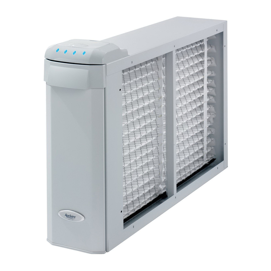
Model 4200 & 4400 Media Air Cleaners
Installation Instructions
CAUTION
Replacement Media: 4200: Model 213 with SelfSeal
Airflow (CFM)
1200
1400
.16
.20
.17
.22
Max. Equipment Weight:
Cabinet will support 400 lb. static load
Air Cleaner and LED Base Operating Environment:
Temperature: 0°F – 140°F
Humidity: 0-90% non-condensing
Air Cleaner Control Operating Environment:
Temperature: 20°F – 120°F
Humidity: 0-90% non-condensing
D
J K
E
F
27-3/8
21-3/16
19-3/4
30-1/16
23-7/8
15-7/16
4400: Model 413 with SelfSeal
1600
1800
.25
.30
.26
.31
E
with Door
F
G H
G
H
J
22-1/16
27-11/16
17-3/4
23-3/8
™
™
2000
.35
.37
90-1333
K
23-5/8
19-5/16
Advertisement

Related Manuals for Aprilaire 4200


Summary of Contents for Aprilaire 4200
- Page 1 Model 4200 & 4400 Media Air Cleaners Installation Instructions WARNING CAUTION 1. High voltage may cause serious 1. To prevent component failure, do not install the air cleaner on the warm injury from electrical shock. air supply or in an area where the temperature may exceed 140°F. This Disconnect power to the may include areas above heat exchangers in downfl...
- Page 2 INSTALL THE AIR CLEANER CABINET LOCATING THE AIR CLEANER 1. Leave sufficient space in front of the air cleaner for the removal of FIGURE 1 – Filtering Media Clearance the filtering media (see Figure 1). 2. DO NOT INSTALL DOWNSTREAM OF A UV LIGHT. UV lamps will cause degradation of the filtering media.
-
Page 3: Installation
INSTALLATION 1. Disconnect power to the furnace or air handler at the electrical service panel. FIGURE 5 WARNING LED Base shown with cover 120 Volts may cause serious injury from electrical shock. Disconnect power to the furnace/air handler before starting installation. Leave power disconnected until installation is completed. - Page 4 OPTION 1 – INSTALL THE AIR CLEANER CONTROL NEAR THE THERMOSTAT Run a 3-conductor cable between the LED Base and the FIGURE 7 low voltage controls of the HVAC equipment. Remove the cover from the LED Base and wire the LED Base to the low voltage controls of the HVAC equipment as shown in Diagram 1.
- Page 5 OPTION 1 – INSTALL THE AIR CLEANER CONTROL NEAR THE THERMOSTAT (CONTINUED) DIAGRAM 2 – Single Transformer Systems THERMOSTAT DISCONNECT EXISTING WIRE FROM THERMOSTAT G (FAN) TERMINAL AND USE WIRE NUT TO CONNECT TO GF WIRE FROM AIR CLEANER CONTROL HEATING COOLING SEE NOTE 2...
- Page 6 OPTION 2 – AIR CLEANER CONTROL MOUNTED ON THE AIR CLEANER Run a 5-conductor cable between FIGURE 9 FIGURE 10 the LED Base and the low voltage controls of the HVAC equipment. Remove the cover from the LED Base and wire to the low voltage controls of the HVAC equipment as shown in Diagram 4.
- Page 7 OPTION 3 – INSTALL THE AIR CLEANER CONTROL NEAR THE HVAC SYSTEM Remove the backplate from the Air Cleaner Control, and install FIGURE 11 the backplate at the desired location for the Air Cleaner Control. Do not install the Air Cleaner Control on supply ductwork. Run a 5-conductor cable between the Air Cleaner Control and the LED Base.
- Page 8 INSTALL THE AIR CLEANER CONTROL SET UP FILTER LIFE INDICATOR – SETTING THE REPLACEMENT FREQUENCY FIGURE 12 Set the jumper on the back of the Air Cleaner Control circuit board, as shown in Figure 12, to the desired frequency for filter changes. TABLE 3 –...