Advertisement
Quick Links
A Division of Dura Automotive Systems
ENGLISH
SAFETY ALERT SYMBOLS
Safety Symbols alerting you to potential personal safety hazards.
Obey all safety messages following these symbols.
WARNING
avoid possible
injury or death
Refer to MPD 87903 and 71125 for complete installation, operation, maintenance
and safety instructions for camper jacks and landing gear respectively.
FOR YOUR SAFETY
READ ALL INSTRUCTIONS BEFORE OPERATING
Installer:
Provide these instructions to the consumer.
Consumer:
Keep documents for future reference.
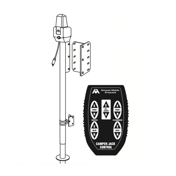
Our remote control is designed for use only with Electric Ball Screw Truck
Camper Jacks (EBSTCJ) equipped for remote control capability and Atwood
Landing Gears. Atwood makes two types of EBSTCJ; one with remote
capability and one without; they are not interchangeable.
PERSONAL INJURY & PRODUCT DAMAGE
To deactivate the wireless system when you are finished press the
•
Activation Switch.
Only operate jacks when camper is unoccupied and contents are
•
secured and properly distributed.
Maintain proper load distribution and a safe distance when raising or
•
lowering camper.
Store remote in a secure place, away from access by children.
•
Remove the battery from the handheld remote before storing to prevent
•
accidental jack activation or continuous remote transmission.
If the remote is continuously activated by a jammed or shorted button,
operation of other remote devices such as vehicle keyless entry systems
and/or garage door openers may be interfered with or prevented.
SPECIFICATIONS:
DESCRIPTION
SPEC
Channels:
1
Frequency:
315 MHz
Operating Temp. Range: -20
o
C to 120
FCC Compliance Statement - Remote Control P/N 85442
This device complies with Part 15 of the FCC Rules. Operation is subject
to the following two conditions: (1) this device may not cause harmful
interference, and (2) this device must accept any interference received,
including interference that may cause undesired operation.
You do not need an FCC license to operate the wireless remote. However, any
changes or modifications to the device will void the user's authority to operate
the equipment.
EXPLOSION
To avoid possible interference with blasting operations, do not use
•
your remote near
ELECTRICAL BLASTING CAPS
-
posted:
TURN OFF TWO
WAY RADIO
Do not use the remote near explosive atmospheres.
•
CAUTION
avoid possible
injury and/or property damage
WARNING
DESCRIPTION
SPEC
Power Source:
9-volt alkaline battery
Weight:
4.0 ounces
o
C
WARNING
or in a
BLASTING AREA
. Obey all signs and instructions.
E
E
E
E
E
E
ALL
ALL
FRONT
FRONT
FRONT
FRONT
JACKS
JACKS
R
R
R
R
R
R
D R I V E R
P A S S E N G E R
D R I V E R
P A S S E N G E R
E
E
REAR
REAR
REAR
REAR
R
R
CAMPER JACK
CAMPER JACK
CONTROL
CONTROL
Explosive atmospheres are often, but not always, clearly marked. They
include fueling areas, fuel or chemical transfer or storage facilities:
areas where the air contains chemicals or particles, such as grain,
dust, or metal powders, and any other area where you would normally
be advised to turn off your vehicle engine.
Disconnect power to the power relay module prior to HiPot testing
•
of the camper or the microprocessor will be damaged.
1. Install the power relay module in a clean, dry interior area protected
from moisture. Use the four (4) 5/32˝ diameter holes for mounting the
module base. Position the base on the mounting surface and secure
it using appropriate hardware for the wall material. Orient antennae
in the position shown (
mounting surface with appropriate hardware (
Failure to orient antennae properly will result in intermittent opera-
•
tion of the wireless remote system.
: Correct polarity must be observed as noted on the circuit board
NOTE
next to 5 & 6-H. The unit will not function if the input power is installed
in reverse polarity. See
A - Driver Front Jack or Leg
B - Passenger Front Jack or Leg
C - Driver Rear Jack or Leveleg
D - Passenger Rear Jack or Leveleg I - Jack Terminal Block
E -
40 AMP Circuit Breaker
L
For all camper jacks
L
or 60 AMP resetable
circuit breaker for
8AWG battery wire.
2.
SUPPLY POWER TO UNIT
be supplied through a 40 AMP circuit breaker (
#8 AWG, +12 VDC from the circuit breaker and the ground wiring, to the
terminal block (
tions and tighten the screws with 16-18 in-lbs of force.
3. Route the two #10 AWG wires from each jack to the terminal block 5-I
& 6-I. Refer to the labels next to each terminal position for driver front,
passenger front, driver rear, and passenger rear jacks. Terminate the
wires for each jack and tighten the screws with 12-13 in-lbs of force.
4. Install the Activation Switch near the floor just inside the door of the
pickup camper (
Plug the flat cable into the left side of the power relay module (
6-J) and route to the location of the activation switch (
other end of the cable into the back side of the activation switch.
: The Key Fob control has an Activate/Learn button on the relay mod-
NOTE
or in areas
ule instead of a separate Activation Switch.
1
LITERATURE NUMBER
REMOTE CONTROL
•Installation •Operation •Maintenance
INSTALLATION
CAUTION
PRODUCT DAMAGE
5 & 6-L). Permanently secure antenna to
FIG
CAUTION
PRODUCT DAMAGE
5 & 6.
FIG
F - Red (-) Motor Gear Box Lead
G - Yellow (+) Motor Gear Box Lead
H - Input Power Terminal Block
J - Flat Cable
K - Dip Switches
L - Antenna
M - Male Connector
N - Female Connector
O - 30 AMP Fuses
: The unit operates from a +12 VDC battery and must
5H & 6-H).Terminate the wires in the labeled posi-
FIG
5-Q) or in an outside compartment of the fifth wheel.
FIG
MPD 87920
WIRELESS
Effective 5/22/07
5-P).
FIG
5E & 6-E). Route the
FIG
5-J &
FIG
5 & 6-Q). Plug
FIG
Advertisement

Summary of Contents for Atwood MPD 87920
-
Page 1: Remote Control
MPD 87920 LITERATURE NUMBER A Division of Dura Automotive Systems WIRELESS FRONT FRONT FRONT FRONT JACKS JACKS REMOTE CONTROL D R I V E R P A S S E N G E R D R I V E R... -
Page 2: Operation
SET UP OF WIRELESS REMOTE CAUTION PRODUCT DAMAGE WARNING Do not over-extend or over-retract jacks. The electric jack has an • PERSONAL INJURY & PRODUCT DAMAGE internal slip clutch to help prevent damage; when clicking sound is Do not replace or charge batteries in a potentially explosive atmos- •... -
Page 3: Motor System
5TH WHEEL TRAILERS 1 MOTOR SYSTEM (KEY FOB) 4 MOTOR SYSTEM TO LIFT TO LIFT 1. Remove the hand held remote control from its secure compartment. 1. Remove the hand held remote control from its secure compartment. 2. Press activate/learn button until red LED illuminaties, then release. 2. -
Page 4: Troubleshooting
For more warranty information contact Atwood before having any work done. ATWOOD LIMITED WARRANTY Atwood Mobile Products warrants to the retail owner and subject to the below men- tioned conditions, that this product will be free of defects in material or workmanship for a period of two years from the original date of purchase. - Page 5 PICKUP CAMPERS 4" (10.16 cm) DOOR 5th WHEEL TRAILERS Control Boards FRONT CONTROL A C T IV AT E / L E A R N C A U T IO N : O N L R E P L A C E F U S E M P D X X X X X W IT H 3 0 A F U S E...