Table of Contents
Advertisement
RD 628
WALL MOUNTED COMBINATION BOILERS FOR CENTRAL HEATING
AND MAINS FED DOMESTIC HOT WATER
INSTALLATION AND
SERVICING INSTRUCTIONS
This appliance is for use with Natural Gas GC NUMBER 47 108 14 (N.G.)
Minimum
Maximum
IMPORTANT: THESE INSTRUCTIONS APPLY IN THE UK ONLY
AND MUST BE LEFT WITH THE USER OR AT THE GAS METER
Read the instructions before starting work - they have been written to make
the installation easier and prevent hold-ups.
GB
APPLIANCE OUTPUTS
Domestic
Central Heating
Hot Water
8.1 kW
8.1 kW
28 kW
28 kW
BEFORE Feb 2004
Before FD483
Advertisement
Table of Contents

Related Manuals for British Gas RD 628


Summary of Contents for British Gas RD 628
-
Page 1: Servicing Instructions
RD 628 WALL MOUNTED COMBINATION BOILERS FOR CENTRAL HEATING AND MAINS FED DOMESTIC HOT WATER INSTALLATION AND SERVICING INSTRUCTIONS BEFORE Feb 2004 Before FD483 This appliance is for use with Natural Gas GC NUMBER 47 108 14 (N.G.) APPLIANCE OUTPUTS... -
Page 2: Table Of Contents
BS5440:1 - Flues and ventilation for gas appliances: Flues Any service work must be carried out by competent engineers BS5440:2 - Flues and ventilation for gas appliances: Air supply. such as British Gas or Corgi registered personnel. BS5449 - Central heating for domestic premises. 2.2 General Information The appliance is set to give the maximum output of 28 kW to the BS5482 - Domestic propane gas burning installations. - Page 3 2.6 Flue Temperature monitoring controls are fitted to prevent overheating. Automatic frost protection is provided together with automatic Multi-Directional Horizontal Flue Kit. pump seizure protection. The gas valve solenoids are automatically checked for gas soundness. Standard Flue Kit can be adjusted from 425mm to IMPORTANT: Where back-flow prevention devices, including 725mm without cutting.
-
Page 4: Technical Data
3. Technical Data Table 1. NOMINAL BOILER RATINGS (10 Minutes After Lighting) BOILER ADJUSTED FOR G20 (Natural Gas) Natural Gas: Net Input = Gross Input x 0.901 BURNER OUTPUT INPUT (Net) GAS RATE PRESSURE m bar. NOTE: With longer flue lengths, not using a restrictor, the mini- 0.97 mum burner pressure will rise to 1.1mbar on G20 appliances. - Page 5 Table 5 PERFORMANCE SPECIFICATIONS PRIMARY WATER CAPACITY litres IP RATING (WHOLE OF BOILER) - WITH/WITHOUT PROGRAMMER FITTED IP 20 MAXIMUM MAINS INLET PRESSURE MINIMUM MAINS INLET PRESSURE (WORKING) FOR MAXIMUM FLOW MINIMUM MAINS INLET PRESSURE (WORKING) FOR OPERATION 0.25 DOMESTIC HOT WATER TEMPERATURE RANGE °C 40 - 60 MAXIMUM CENTRAL HEATING FLOW TEMPERATURE...
- Page 6 Fig. 6. Side flue opening Fig. 3. Appliance casing dimensions and required clearances for installation/servicing All dimensions in mm All dimensions in mm Fig. 4. Appliance casing dimensions and Fig. 7. Pipework connections required clearances (side view). Valves shown closed. View of underside of appliance showing connections All dimensions in mm...
-
Page 7: Siting The Appliance
4. Siting The Appliance Fig. A. IP Zones. Do not fit appliance in shaded areas. The appliance may be installed in any room but refer to the requirements of the current IEE Regulations and, in Scotland, the relevant electrical provisions of the Building Regulations with ZONE 1 respect to the installation of appliances in rooms containing baths or showers. -
Page 8: Flue Terminal Positions
5. Flue terminal positions Fig. B. Siting a vertical flue terminal Terminal position for a flat roof. The flue system must be installed following the requirements of BS5440: 1. Standard horizontal flue kit length is 330 – 725mm with extension kits for flues upto 4m for natural gas. The terminal must not cause an obstruction or the combustion products a nuisance. -
Page 9: Air Supply
6. Air Supply 7. Sealed System 6.1 A separate vent for combustion air is not required. Refer to The system must comply with requirements of BS6798 and BS5440:2. BS5449 and must not be operated without being full of water If the appliance is in a cupboard or compartment then, because and correctly pressurised. -
Page 10: Domestic Hot Water
Fig 10 - System Fill Fig 11 - System make up 300mm Above the highest point Mains of the system Water Supply 1.Central Heating Return 2.Auto Air vent 3.Non-return Valve 4.Make-up Vessel 5.Stop Cock 6.Fill Point 8. Domestic Hot Water 9. - Page 11 Fig. 12. Wiring diagram. Pressure Switch white Overheat cut-off device black CH sensor (front of heat exchanger) Flame sense electrode Spark electrode Gas valve Regulator & Solenoid Valve Pump Flow turbine Main Solenoid Valve DHW sensor Spark Generator Diagnostic Module Code Plug Control Board green/yellow...
- Page 12 Fig. 13. Functional flow diagram. Inputs Outputs DHW control knob CH Control knob Electronics/ microprocessor (Safety Low Voltage) Gas valve mode switch Reset button Convert AC to low Electronics voltage electronics Electronics Pump Electronics...
-
Page 13: Installing The Appliance
Fig. 14. Access to internal fuses and Fig. 15 . Mains electricity connections. electrical connections. Ns Ls 230V MAINS 230V module 1. Connection cover fixing screws 3. Control panel 2. Connection cover 4. Connections for internally fitted flues]. 11. Installing The Appliance 11.5 Wall Mounting and Manifold Assembly Fit the plugs and insert the bottom screws. - Page 14 Fig. 17 . Manifold assembly Fig. 19 . Wall mounting frame Wall Frame Wall Fibre Frame Washer 1. Wall mounting frame 2. Hanging bracket 3. Appliance Flow Flow 4. Support hook Cold Lift the appliance to the wall, engage in the top support and Inlet Return lower onto the manifold assembly.
- Page 15 Fig. 21. Inner case and facia fixing Fig. 22. Flue spigot and restrictor 1. Flue spigot fixing screws 2. Flue spigot 3. Restrictor ring 4. Flue spigot fixing holes Fig.23. Standard flue assembly Terminal assembly Flue Fixing screw turret assembly Telescopic adjustment Appliance casing...
- Page 16 Fig. 24. Extension duct Terminal assembly Flue Fixing screw Fixing screw turret assembly Appliance casing Ducts of equal length Fig. 25. Flue duct length - side Terminal assembly Flue turret assembly It will be necessary to cut the ducts Fig. 26. Flue duct length - rear If L is between 725 - 1175mm (1 extension)
- Page 17 Prepare the flue assembly as described in Section 11.8. Fig. 27 . Flue Turret Fixing Fit the rubber sealing gasket centrally onto the terminal assembly and tighten the clamp. Refer to Fig. 28. Apply the plastic tape to the air duct to be in contact with the external brickwork.
- Page 18 If Z is greater than 725mm then two extension duct assemblies will Connect the mains supply lead to the appliance and secure in be required, the first assembly being cut to length as plain tubes. the cable clamp. Make sure the lead is isolated before connection.
- Page 19 Fig 36 - Mains Voltage External Controls Fig. 34. Programmer cover Connections spare Ns Ls L spare Ns Ls L Remove Link Remove Link Motor 230 V Room Thermostat Connections 230 V Programmer Connections 230 V room thermostat and Programmer Connections 1.
- Page 20 FILLING LOOP ASSEMBLY CONNECTION 6. Fit two M4 screws complete with washers to each of the two con- nections. NB. It is not possible to access the third screw hole so this can be left. The filling loop assembly is packed in a box with the installation Do not attempt to turn the brass hexagon connectors.
-
Page 21: Commissioning The Appliance
Fig. 41. Pump venting. 12. Commissioning The Appliance 12.1 Water Treatment: For optimum performance after installation, this boiler and its associated central heating system Pump should be flushed in accordance with the guidelines given in BS7593: 1992 – Treatment of water in domestic hot water heating systems. - Page 22 Unscrew and remove the control connector cover to display the cooled to a pre-set temperature. mode switch. Refer to Fig 42. 12.7 Central Heating Check that all the radiator valves are open. Check that the Check that all the radiator valves are open. system is fully vented, pressurised and set to the required Check that the system is fully vented, pressurised and set to the pressure as indicated on the gauge.
- Page 23 Appliance Data Monitoring 8. Push the switch SW1 on the ADM while powering up the appliance, see Fig. 45. If the external Gateway module is fitted, then the operating system must be commissioned at this stage. Observe LED on ADM flashing. The flashing rate is 0.5 Hz, the ADM is now in “House Address Acquisition mode”.
-
Page 24: Handover
Any service work must be carried out by competent registered engineers such as British Gas or Corgi registered personnel. 14.2 Inspection Ensure that the appliance is switched off and electrically Fig. - Page 25 Fig. 49. Inner case components 1. Flue hood 8. Combustion chamber fixing screw 2. Primary sensor 9. Inner case 3. Heat exchanger 10. Fan assembly 4. Combustion chamber assembly 11. Inner case cover fixing (top) 5. Spark electrode assembly 12. Combustion sensor point 6.
- Page 26 Inner Case Cover Unscrew the four screws and remove. Refer to Fig 47. 14.4 Component Cleaning Combustion Chamber Unscrew the two screws at the top and Only use a non-metallic brush to clean components. the two wing nut extended screws at the sides, pull Do not use a metal probe to clean the injectors.
-
Page 27: Replacement Of Parts
15.1 Gas Valve 15. Replacement Of Parts Unscrew the union connections above and below the gas valve and remove the assembly. Disconnect/unplug the electrical IMPORTANT: Turn off the gas supply and electrically isolate connections from the valve. the appliance before replacing any components. Use new gaskets when replacing the valve. - Page 28 15.2 Spark Electrode Fig. 55. Flame sense electrode Remove the inner casing cover and the combustion chamber. Carefully pull off the lead from the electrode. Unscrew the screw and remove the assembly. Refer to Fig 54. Ensure that the electrode is at the correct height above the burner blade.
- Page 29 15.5 Combustion Chamber Insulation, Front &Sides Fig. 59. Relief valve boiler drain connection Remove inner casing door and combustion chamber. Remove damaged insulation, replacement is the reverse of removal. See Fig 57. Removal must be by sliding panels. Combustion Chamber Insulation, Rear Remove side panels before removing heat exchanger as described in 15.21.
- Page 30 15.9 Inlet Water Filter 15.12 Clock/Programmer Remove the flow switch as described in 15.8 preceding. Remove the facia by gently pulling it away from the boiler to Taking care, remove flow restrictor assembly from the flow release the clips. turbine. Carefully clean wire mesh by back flushing with water or Remove the clock/programmer assembly by releasing the clip at replace assembly if necessary.
- Page 31 15.15 Primary [ch] Sensor Fig. 64. Primary (CH) sensor. Remove the clip-on facia cover, cabinet and inner casing cover. Carefully pull-off the connections. Release the clip and lift out the sensor. Refer to Figs 49 & 64. Do not omit the heat transfer paste when fitting the replacement sensor.
-
Page 32: Short Parts List
Fig. 67. Primary heat exchanger 1. Heat exchanger 2. CH flow/return pipes 3. DHW inlet/outlet pipes 4. Seal 5. Overheat thermostat 6. Primary sensor 22 Air pressure Switch Squeeze and push down the two plastic lugs and remove the pressure switch from under the bracket. See Fig 68. Remove the fixing clip (see Fig 68) and fit to the new air pressure Fig. - Page 33 16. Short Parts List G.C. No. Part Part No. E88-143 Burner 28 NG RSF 8 716 105 008 0 E88-145 Gas Valve CE428 8 747 003 601 0 E88-146 Air Pressure Switch 8 716 104 896 0 E88-169 E lectrode Set (Flame and Ignition) 8 716 101 901 0 E88-170 Overheat Stat...
-
Page 34: Operational Flow Diagram
17 - 18... - Page 35 17. Operational Flow Diagrams CENTRAL HEATING FUNCTION Room thermostat and/or mains programmer (or link) On MAIN SWITCH facia programmer (if fitted) On CH control knob On Fifteen second Modulate gas Pump on. minimum to maintain Fan ON/ burner CENTRAL flow ignition pressure then DEMAND...
-
Page 36: Fault Finding
OVERRUN FUNCTION Pump on if primary temp Pump overrun above 80° END DHW function active until temp DEMAND for 3 minutes below 75°C Fan low speed if primary temp Fan low speed 35 seconds above 80°C until below 75°C. Pump runs END CH DEMAND 3 minutes... - Page 37 18. Fault Finding Note: This fault-finding information is for guidance only. Worcester Heat Systems cannot be held responsible for costs incurred by persons not deemed to be competent. By flashing at various rates, the oval shaped facia light will indicate specific fault conditions. If this is used with other observations during a fault, then every normal fault can be identified.
- Page 38 NOTE: It is normal for there to be no facia lights if the boiler is in normal overtempera- ture condition. Continue this test if this fault occurs when the appliance is cold. Is there a 230V AC live supply across Check electrical Terminal ST2 pins L supply to boiler.
- Page 39 Disconnect the 3 way in-line connector to the turbine. Is there continuity in Replace main Is there 5VDC between the main harness? harness. the two outer pins (main harness side)? Take care not to damage the pins. Replace control board. Re-connect the 3-way connector and open a tap to run the turbine.
- Page 40 Is the gas supply Rectify gas supply connected and at the problem. correct pressure? Remove front panel. Remove inner cover. Reset and restart the Reset and restart the Are the electrodes and Repair or replace boiler. Can a flame be boiler.
- Page 41 Turn off boiler. Remove inner casing cover and inspect the primary sensor (on heat Re-fix sensor to pipe. exchanger in front of overheat thermostat). Is it correctly fixed to pipe? Remove combustion chamber cover. Replace flame sensor Is the sense electrode or wiring.
- Page 42 Is the Code plug fitted Fit/push fully home fully home? Is the multiway connector at board position ST16 pushed Push fully home fully home on to the board? Check the DHW sensor. Is it correctly Re-fix sensor onto pipe fitted onto the pipe with heat conductive paste between the pipe and sensor?
- Page 43 Replace multiway connector to position ST16 (but not fan connector at ST1) and Replace control board. reset/restart the In the unlikely event boiler. of this not solving the Is there mains 230V problem replace code across the right (L) plug. and left (N) tracks at board position ST1? NOTE: Take care not to...
- Page 44 Is the boiler in a very Replace control board. cold environment (less Note: A damp board than 5°C)? could cause this fault. Boiler is running in “Autofrost stat” mode. See Section 17. Hot water Hot water sensor temperature always could be off or poorly too hot during a fixed to pipe.
- Page 48 This manual is to be used in conjunction with the variant part number of the bar code below: Manufactured exclusively for British Gas by Worcester Heat Systems Limited ( Bosch Group), Cotswold Way, Warndon, Worcester WR4 9SW. Telephone: (01905) 754624. Fax: (01905) 754619.
-
Page 49: Installation Instructions
ROOM SEALED FLUE TERMINAL KIT For use on the Danesmoor Front Service Room Sealed Oil Appliances INSTALLATION INSTRUCTIONS The appliance/flue system should be installed by a competent person... -
Page 50: General Information
Contents 3. Flue Lengths, Bends and Extensions. 1. Installation Regulations Page 1 3.1. The maximum flue length allowable is 2.5 metres 2. General Information Page 1 as shown in Figs 1 and 2. 3. Flue Lengths, Bends & Extensions Page 1 3.2. - Page 51 Fig. 1. Rear discharge flue systems. 100mm 100mm 100mm 100mm Total straight length of L must not exceed Side view Side view 2500mm Fig. 1a. Low level horizontal flue with one 90° Bend Fig. 1b. Low level horizontal flue with extensions and one 90° bend 100mm 100mm Centre of flue terminal...
- Page 52 Fig. 2. Side discharge flue systems. 100mm 100mm 185mm Centre of flue terminal to floor 754mm H = 754 + L1 Front view Front view Total straight length of L must not Total straight length exceed of L1 + L2 must not 2500mm exceed 2500mm Fig.
- Page 53 4.3. Left and Right Side Discharge Low Level passageways is not recommended. Flues as shown in figure 2a 5.3. The terminal must not cause an obstruction or Using the Standard RS flue kit the discharge cause a nuisance as a result of either If L is between : flue gases or terminal noise.
- Page 54 tion and screwing through with the self tapping Note: To create a good seal between the boiler screws provided. and air box assembly only use the flue ring gas- ket supplied within the RS flue kit. Fig. 6a. Fitting of rubber sealing gasket 6.4.
- Page 55 6.13. Check that the telescopic flue slides freely. Method 2. Fasten together the flue terminal and any extension Note: The sliding section of the telescopic flue termi- sections intended to pass through the wall, in a simi- nal must be fixed using the self tapping screws pro- lar manner to 6.6.
- Page 56 an extension is fitted. the telescopic terminal section using the two self 6.35. Using the flue as a guide, mark the position of tapping screws provided. the hole required to accept the flue terminal or meas- 6.45. Slide the boiler back into position carefully ure the flue centre position as shown in figs 1 and 2.
- Page 57 Worcester Heat Systems Limited, Cotswold Way, Warndon, Worcester WR4 9SW. Telephone: (01905) 754624. Fax: (01905) 754619. Technical Helpline 08705 266241. This booklet is accurate at the date of printing but will be superseded and should be disregarded if specifications and/or appearances are changed in the inter- ests of continued improvement.
- Page 58 RD 628 G.C. NUMBER: 47 108 14 USER INSTRUCTIONS & CUSTOMER CARE GUIDE...
- Page 59 The result is that your new RD 628 appliance offers you the very best of everything - quality, efficiency, economical running costs, proven reliability and value for money.
-
Page 60: General Description
WARNING: This appliance must be earthed and protected by a 3 amp fuse to BS 1362. ELECTRICITY SUPPLY: 230V ~ 50Hz IMPORTANT: To get the best from your RD 628 appliance please read these instructions carefully. NOTE: In the event of a fault the appliance should not be used until the fault has been corrected by a competent person. - Page 61 Hot Water Mode: When a demand is made for hot water by opening a tap or shower, the flow turbine will energise the boiler. The burner will light at its maximum setting and hot water will be delivered to the tap or shower.
-
Page 62: General Notes
GENERAL NOTES CENTRAL HEATING SYSTEM During the first few hours of operation of the central heating system, check that all radiators are being heated at an even rate. Should the upper area of a radiator be at a lower temperature than the base of the radiator, it should be vented by releasing air through the venting screw at the top of each radiator. -
Page 63: Room Thermostat
CLEARANCES Unventilated Your installer will compartment have provided adequate Left-hand side space around the Right-hand side appliance for safety and In Front servicing. Do not restrict this space by the above flue elbow Above the casing or turret addition of cupboards, Below shelves etc. -
Page 64: Use In Hard Water Areas
Annual servicing is important in order to ensure continuing high efficiency and long life for your appliance. Three star service cover from British Gas can offer comprehensive cover for your central heating - please call 0845 9 60 50 40 for further details. -
Page 65: Domestic Hot Water Temperature
OPERATION OF CONTROLS The appliance is fitted with the following controls: OPERATING SWITCH In the ‘0’ position there is no mains electricity to the control board. In the ‘I’ position mains electricity is connected to the control board. CENTRAL HEATING TEMPERATURE CONTROL The position of this knob will determine the temperature of the water delivered to the radiators between fully clockwise and anti-... -
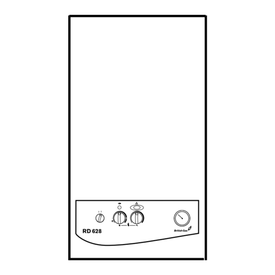
Page 66: Indicator Lights
INDICATOR LIGHTS Flame detection indicator: OFF: Burner off Burner on Fault indicator: FLASHING SLOW: Ignition lockout or (once per second) boiler overheat FLASHING FAST: Appliance fault (five times a second) Fig. 2. Controls. Mains electricity Flame detection Fault indicator and System pressure On/Off indicator... -
Page 67: Electricity Supply
TO LIGHT AND STOP THE APPLIANCE TO LIGHT THE APPLIANCE Check that the water valves to the central heating circuit are open. Check that the black needle on the pressure gauge is not below the required pressure. Switch on the mains electricity. Set the room thermostat to maximum. - Page 68 If ignition lockout has occurred, the fault indicator will flash slowly (approximately once per second). The appliance can be reset by pressing the reset button and holding in for 5 seconds. Check that the gas supply has not been interrupted. If this condition continues to occur, then call a service engineer.
- Page 69 APPLIANCE FAILS TO OPERATE If your RD 628 appliance should fail to operate correctly, please call British Gas on: 0845 9 60 50 40 IMPORTANT Do not touch or adjust any sealed component...
- Page 70 MAINTAINING YOUR APPLIANCE Your new RD 628 gas-fired appliance represents a long-term investment in a reliable, high quality product. In order to realise its maximum working life, and to ensure it continues to operate at peak efficiency and performance, it is...
- Page 72 YOUR RD 628 GUARANTEE This appliance is guaranteed against faulty materials or workmanship for a period of twelve calendar months from the date of installation subject to the following conditions and exceptions. 1. That during the currency of this guarantee must be accompanied by...
-
Page 73: Guarantee Registration
You should complete and return the postpaid Guarantee Registration Card within 14 days of purchase. The card will register you as the owner of your new RD 628 appliance and, while this will not affect your statutory rights in any way, it will assist us to maintain an effective and efficient customer service by establishing a reference and permanent record for your boiler.