Table of Contents
Advertisement
Quick Links
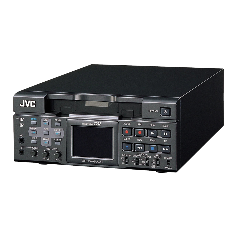
DV VIDEO CASSETTE RECORDER
BR-DV6000U
Thank you for purchasing this JVC product.
Before operating this unit, please read the
instructions carefully to unsure the best
possible performance.
MENU
RESET
DISP
Mini
PROFESSIONAL
SEARCH–
SET
SEARCH+
MIC
HOLD
BLANK
CUE UP
PHONES
REC LEVEL
BR-DV6000
CH-1/3
CH-2/4
INSTRUCTION MANUAL
OPERATE
A.DUB
REC
PLAY
PAUSE
EJECT
REW
STOP
FF
AUDIO
INPUT
COUNTER
MONITOR OUTPUT
SELECT
REMOTE
CTL
L
CH-1/2
DV
TC
MIX
MIX
LINE
UB
R
CH-3/4
Y/C
LOCAL
(CPN)
For Customer Use:
Enter below the Serial No. which is
located on the rear of cabinet. Retain
this information for future reference.
Model No.
Serial No.
BR-DV6000U
LLT0033-001B-H
Advertisement
Table of Contents

Related Manuals for JVC BR-DV6000


Summary of Contents for JVC BR-DV6000
- Page 1 DV VIDEO CASSETTE RECORDER BR-DV6000U MENU Mini SEARCH– HOLD PHONES Thank you for purchasing this JVC product. Before operating this unit, please read the instructions carefully to unsure the best possible performance. INSTRUCTION MANUAL RESET A.DUB DISP PROFESSIONAL SEARCH+ EJECT...
- Page 2 1. Read all of these instructions. 2. Save these instructions for later use. 3. All warnings on the product and in the operating instructions should be adhered to. 4. Unplug this appliance system from the wall outlet before cleaning. Do not use liquid cleaners or aerosol cleaners.
-
Page 3: Safety Precautions
WARNING: The battery used in the BR-DV6000U must be replaced by a JVC authorized service dealer only. This digital apparatus does not exceed the Class B limits for radio noise emissions from digital apparatus as set out in the interference-causing equipment standard entitled “Digital Apparatus”,... -
Page 4: Main Features
● Optionally, the RS-232C interface can be used. ● Recording and playback of time codes ● Time code I/O terminal Slave lock is allowed if BR-DV6000 is connected to an external time code generator. ● SYNC IN terminal logo can External synchronization signals can be input. -
Page 5: Table Of Contents
Presetting the time code ... 59 Recording the time code ... 60 Playing back the time code ... 63 EDIT Editing with an RS-422A/JVC bus edit remote controller ... 64 Using a non-linear editing system ... 68 MENU SCREENS Structure of the Menu screens ... 69 Setting the menus ... -
Page 6: Remarks Of Usage
INTRODUCTION Remarks of usage Place of storage and use Avoid storing or using this VCR in the following places: ● Excessively hot or cold places beyond the al- lowable temperature for operation (5˚C – 40˚C). ● Humid or dry places beyond the allowable humidity range for operation (30% –... -
Page 7: Regular Maintenance
For details, refer to page 100, “Checking the hour meter.” : For details on the maintenance plan and fee, consult with your JVC-authorized service agent. • If the head is dusty, “HEAD CLEANING RE- QUIRED!” will be displayed on the monitor when this unit plays a tape. -
Page 8: Cleaning Tape
Frequency of 1 to 2 times every cleaning 5 hours Cassette tape BR-DV6000 can record onto and playback stan- dard DV and mini DV cassette tapes (for SP mode only). Use the following JVC cassettes with the logo. ● Standard DV cassettes ●... -
Page 9: Condensation
• Prevention of condensation When transporting BR-DV6000 from a cold to a warmer place abruptly, first remove the cassette tape. Then place BR-DV6000 in a plastic bag and seal it before transporting. Take out BR-DV6000 from the sealed plastic bag only after it has the same temperature as the surroundings. -
Page 10: Names And Functions Of Parts
Insert a standard DV cassette or a mini DV ☞ cassette. ( Page 38) • When BR-DV6000 is in the OPERATE OFF state and a cassette is loaded, it changes to the OPERATE ON state. • With a cassette loaded, the LED lights up in green. - Page 11 STILL mode. In the RE- CORDING PAUSE or STILL mode, the green LED lights up. • When BR-DV6000 is in the STILL mode, hold down the A.DUB button and press this but- ton to enter into the audio-dubbing pause mode.
- Page 12 [REMOTE/LOCAL] switch This switch is used to select how BR-DV6000 is to be operated. LOCAL : Use this setting if BR-DV6000 is to be controlled with the key operation of the unit. REMOTE : Use this setting if BR-DV6000 is to...
- Page 13 Memo ● For the MIX setting, noise is sometimes gen- erated. If it occurs, set it to CH-1/2 or CH-3/4. ● In the 48 K audio mode, it is fixed at chan- nels CH1 and CH2 regardless of the setting of the switch.
- Page 14 ☞ [MENU] button If this button is pressed when BR-DV6000 is in the STOP/STILL mode or when no cassette is loaded, the menu is displayed on the LCD or the monitor connected to the VIDEO MONITOR OUT terminal.
- Page 15 [BLANK/9] button • When BR-DV6000 is in the stop mode, press this button to start blank search. It searches the unrecorded part of the tape and goes into the still mode.
-
Page 16: Rear Panel
NAMES AND FUNCTIONS OF PARTS VIDEO LINE MONITOR SIGNAL DC12V [VIDEO LINE IN] terminal (BNC) This is the input terminal for composite video signals. • To input video via this terminal, set the IN- PUT SELECT switch located on the front panel to “LINE”. - Page 17 [SYNC IN] synchronization input terminal (BNC) This is the terminal for inputting reference syn- chronization signals from an external source. For external synchronization signals, input com- posite video signals of 1V (p-p) or lower (e.g., black burst signal). ☞ Page 29 “Synchronization signal”) [TIME CODE IN] terminal (BNC) This is the SMPTE-compliant time code input terminal.
- Page 18 OPERATE indicator located on the front panel lights up. (The indicator turns red when BR- DV6000 is in the OPERATE OFF state) ● Whether to set BR-DV6000 to enter the OP- ERATE ON mode or OPERATE OFF mode when power is supplied to the terminal can be selected with DC IN MODE in the SYS- TEM (2/2) Menu screen.
- Page 19 This terminal is for connecting to an RS-422A serial interface-compatible editing remote con- troller (e.g. RM-G820). With this terminal, BR-DV6000 can be used as a player or recorder of an editing system. To operate BR-DV6000 with RS-422A, perform the following settings.
-
Page 20: On-Screen Display
ON-SCREEN DISPLAY Besides E-E images and playback images, the monitor connected to the VIDEO MONITOR OUT terminal provides the following on-screen information. Press the DISPLAY button to display the same information on the LCD screen of BR-DV6000. DISP button A.DUB... -
Page 21: Status Display
ON-SCREEN DISPLAY Status display: It displays the current settings and operating status. 3 2 K C H – 1 / 2 A S S E M W A R N I N G 7 0 0 1 D R UM MO T O R F A I L U R E R E C I N H I B I T S T A N D B Y - O F F 0 3 / 0 4 / 0 3... - Page 22 ON-SCREEN DISPLAY Item Counter display – Status display – (continued) 3 2 K C H – 1 / 2 A S S E M W A R N I N G 7 0 0 1 D R UM MO T O R F A I L U R E R E C I N H I B I T S T A N D B Y - O F F 0 3 / 0 4 / 0 3...
-
Page 23: Status/Event Display
1 1 : 2 0 : 0 0 T C R 0 2 : 0 0 : 0 0 : 0 0 Displays the VCR operation mode, including: PLAY, EJECT, FF, REW, STANDBY-ON, STANDBY-OFF, STILL, REC, REC PAUSE, A. DUB, A. DUB PAUSE, ASSEM EDIT, INSERT EDIT, SHTL (shuttle search), JOG, BLANK SRH (blank search), NO CASSETTE (cassette tape not loaded), OPERATE OFF. -
Page 24: Alarm Display
BR-DV6000 is not in good condition, e.g., dirty head. ● “A” display : The state of BR-DV6000 is displayed. It continues to be displayed until the error state is corrected. This display is not affected by the setting of the display mode. - Page 25 Display The user attempted to perform audio dubbing on a tape that is not ready for A. DUB INHIBIT (REC TAB) recording (the rear switch is set to SAVE). A. DUB INHIBIT This message is displayed when audio dubbing is attempted under the following (48 K) conditions.
-
Page 26: Lcd Display
STOP mode, and the playback sound level during playback. The reference recording level of BR-DV6000 is –20dB. • For playing a tape recorded with a home-use DV ma- chine with a reference level of –12 dB, set AUDIO OUT LEVEL to –12 dB. - Page 27 • The CTL counter is displayed as a 7-digit number with + or –. The time code/user’s bit is displayed as an 8-digit number. 8 VCR mode display Displays the operation mode of the VCR. The reservation of mode is displayed in blinking light. NOCAS (no cassette tape), EJECT, STBON (standby-...
-
Page 28: Connection
Component Output Video output, e.g., VCR Output signal When BR-DV6000 enters the STOP, REC or EDIT mode, the input signal (E-E image) is out- put. In the PLAYBACK mode (including the play- back of the pre-roll part during editing), play- back images are output. - Page 29 To edit DV signals, synchronization signal in- put is required. Types of synchronization signal: BR-DV6000 is operated based on one of the following 3 types of synchronization signal. • Synchronization signals produced by the syn- chronization signal generator inside the VCR (INT) •...
-
Page 30: Connecting Audio Signals
Analog audio (2 channels) Output Audio input of VCR Output signal When BR-DV6000 is in the STOP, REC or EDIT mode, signals (EE sound), which have been input, are output. During the PLAYBACK mode (including the playback of the pre-roll part during editing), the playback sound is output. -
Page 31: Digital Output
● Connecting to a monitor TV A monitor TV can be connected to the AUDIO MONITOR OUT terminal. The sound output from the AUDIO MONITOR OUT terminal is monaural. • The volume is adjusted through the monitor • The output channel can be selected with the AUDIO MONITOR switch on the front panel (Refer to the following table). -
Page 32: Connecting To Editing System
CONNECTION BR-DV6000 is equipped with 2 remote terminals, for the JVC bus and RS-422A for editing pur- poses. When a JVC bus-compatible editing remote controller is used: For the editing remote controller, use RM-G800 or RM-G805. Example: BR-DV6000 as player and recorder for cut editing of digital signals. - Page 33 When an RS-422A-compatible remote controller is used: For the editing remote controller, use RM-G820. Example: use BR-DV6000 as player and recorder for cut editing of analog signals. Monitor VIDEO MONITOR VIDEO OUT Player AUDIO OUT VIDEO COMPONENT REMOTE2 LINE AUDIO...
-
Page 34: Connecting With Serial Remote Terminals
Dubbing of playback images or sound with other machines using the SERIAL RE- MOTE OUT terminal. When BR-DV6000 is in the playback mode, the REC command can be output from the SERIAL REMOTE OUT terminal (REPLICATION function). With this function, a tape loaded in BR-DV6000 can be dubbed on another unit. -
Page 35: Connecting The Ac Adapter
“OPE ON”, the OPERATE in- dicator will light up in green. (OPERATE ON mode) • Supply power to BR-DV6000 using the supplied AC adapter. Do not use other power sources. • Do not unplug the DC cord and/or the power cord during recording or playback. -
Page 36: Preparation
• BR-DV6000 enters the OPERATE OFF mode and the OPERATE indicator lights up in red. If BR-DV6000 is not to be used for a long period of time, unplug the AC adapter. To unplug the AC adapter, remove the power cord from the power outlet first. -
Page 37: Operation Method
OPERATION LOCK mode BR-DV6000 comes with an operation lock function to prevent unauthorized or incorrect operation. In the OPERATION LOCK mode, the operation buttons and slide switches of BR-DV6000 are disabled. However, the OPERATE ON and MENU operations are effective. -
Page 38: Loading/Ejecting Cassette
Ensure that no cassette tape is loaded. With no cassette tape loaded, the cassette LED is off. When no cassette tape is loaded, the status display for the VCR operation mode shows “NO CASSETTE” on the monitor or the LCD. -
Page 39: Setting The Lcd Display
BLANK CUE UP PHONES REC LEVEL COUNTER M BR-DV6000 CH-1/3 CH-2/4 DISPLAY (2/2) Menu screen – – – D I S P L A Y [ 1 / 2 ] – – – L C D B R I G H T N E S S... -
Page 40: Setting/Displaying Date And Time
SEARCH+ BLANK CUE UP HOLD PHONES REC LEVEL BR-DV6000 CH-1/3 CH-2/4 Press the OPERATE button to turn on the power and set it to the STOP mode. Press the MENU button to display the TOP MENU screen. Displaying the CLOCK ADJUST Menu. - Page 41 – – – C L O C K A D J U S T – – – D A T E 0 3 / 0 4 / 0 3 T I M E 1 2 : 0 0 P A G E B A C K Selecting date/time display The date and time data can be displayed on the monitor or LCD on-screen display (status display).
-
Page 42: Recording
XLR IN board. Setting the SYSTEM Menu ( ● LONG PAUSE TIME This is for setting the time for BR-DV6000 to enter the tape protection mode if there is a long recording pause. ● INDEX WRITE: SYSTEM (2/2) Menu This is for selecting whether to record index sig- nals automatically when recording starts. -
Page 43: Recording Procedure
Allow at least an interval of 1 minute between recordings of in- dex. ❈ Index signals cannot be recorded with the REC button of the remote controller. Use the record button of BR-DV6000. – Recording procedure – 3. 5 PLAY button... -
Page 44: Audio Dubbing
• When audio dubbing is performed on tapes re- corded on other devices, it may not record cor- rectly. Record with BR-DV6000 before perform- ing audio dubbing. – Audio dubbing – PLAY button... -
Page 45: Backup Recording Function
In combination with DV equipment, BR-DV6000 can perform continuous, long-hour recording. BR-DV6000 can be set as the backup unit connected to a DV camcorder (GY-DV300/DV500/DV550/ DV5000, etc.). When the recording tape of the source unit nears its end, BR-DV6000 can start recording, enabling long-hour recording. -
Page 46: Recording With Serial Remote Terminals
RECORDING Recording can be turned ON/OFF with a serial remote controller or foot switch connected to the SERIAL REMOTE IN terminal located at the rear panel of BR-DV6000. MENU RESET DISP Mini PROFESSIONAL SEARCH– SEARCH+ HOLD BLANK CUE UP PHONES... -
Page 47: External Timer Recording
RECORDING BR-DV6000 can start recording automatically when the power is supplied. Using a commercially available timer, recording can start at a pre-determined time. Timer, etc. Supplied AC adapter Memo Use an external timer ex- clusively to control the start of VCR operation. -
Page 48: Playback
STILL mode for a long time. (5, 3, 2, 1 minute or 30 seconds) ● LONG PAUSE MODE For selecting the state of BR-DV6000 when it enters the tape protection mode after it stayed in the STILL mode for a prolonged period of —... -
Page 49: Basic Playback Procedure
Press the PLAY button. Stop playback. Press the STOP button. Fast forward/rewind When BR-DV6000 is in the STOP mode, press the FF button to fast-forward the tape. When BR-DV6000 is in the STOP mode, press the REW button to rewind the tape. -
Page 50: Special Playback Functions
Set “;, :” KEY FUNC in the SYSTEM (1/2) Menu screen to VAR. ::Operation: Set BR-DV6000 to the PLAYBACK or the STILL mode. Press the FF button to start fast-forward playback. Press the REW button to start reverse playback. Press the SEARCH+/: button to increase the search speed. - Page 51 (CPN) REW button Increasing the playback speed by 7% Set BR-DV6000 to the PLAYBACK, STILL or STOP mode. Press the FF button while holding down the PLAY button. While the buttons are held down, the playback speed is increased by 7%.
-
Page 52: Search Function
This function searches to the position where the index signal is recorded. MENU DISP RESET Mini PROFESSIONAL SEARCH– SEARCH+ HOLD BLANK CUE UP PHONES REC LEVEL BR-DV6000 CH-1/3 CH-2/4 SEARCH– SEARCH+ button button Monitor screen INDEX+1 Index search progressing: displayed on the screen (The number denotes the corresponding index position.) Blank search This function searches unrecorded parts of the tape. -
Page 53: Repeat Playback
PLAYBACK Three types of repeat playback are available for BR-DV6000. The repeat playback function can be set with REPEAT MODE in the SYSTEM (1/2) Menu screen. SYSTEM (1/2) menu screen — — — — — — — — — INDEX repeat playback ●... -
Page 54: Multi Cue-Up
DISP PROFESSIONAL SEARCH+ EJECT BLANK CUE UP REC LEVEL COUNTER BR-DV6000 CH-1/3 CH-2/4 COUNTER switch CUE UP button Set the COUNTER switch to TC. Load a tape with time codes recorded. Press the CUE UP button. ¥ The CUE UP screen appears on the monitor or the LCD. - Page 55 Mini PROFESSIONAL SEARCH– SEARCH+ BLANK CUE UP HOLD PHONES REC LEVEL BR-DV6000 CH-1/3 CH-2/4 ; button 9 button : button Memo If the COUNTER switch is set to CTL or UB while the Multi Cue-up screen is be- ing displayed, the display returns to the normal screen.
-
Page 56: External Timer Playback
Use an external timer ex- clusively to control the VCR operation. If the power is cut off by an external timer and the VCR operation stopped while the tape is running, BR-DV6000 or the tape may be damaged. DISP button MENU RESET DISP Mini PROFESSIONAL SEARCH–... -
Page 57: Dubbing With Another Machine Using The Serial Remote Out/Dv Terminals
When the REPLICATION function is turned ON and BR-DV6000 is set to the PLAYBACK mode, the REC command will output from the SERIAL REMOTE OUT terminal or the DV terminal. With this function, the video and sound being played back on BR-DV6000 can be dubbed by another machine by simply pressing the PLAY button. -
Page 58: Time Code
TIME CODE BR-DV6000 can record and play back SMPTE-compliant time code and user’s bit. With the time code function, accurate positions of the tape contents can be specified to enhance editing preci- sion and operation efficiency. During recording or playback, the time code and user’s bit are dis- played on the monitor or the LCD. -
Page 59: Presetting The Time Code
● When the hour digit is blink- ing, the frame digit starts blinking when the ; button is pressed. ● If a user’s bit is input with its all digits set as “F”, BR-DV6000 converts FFFFFFFF to FFFFFFFE before recording. SET button DISP/8 button MENU... -
Page 60: Recording The Time Code
COUNTER switch Preset time code ● Stopping the power supply to the DV IN terminal of BR-DV6000 cancels the preset value of the time code generator. ● With FREE RUN, if the mode is changed from OPERATE ON to OPERATE OFF and back to OPERATE ON before BR-DV6000 is restarted, the advance of the time generator may deviate. - Page 61 Recording time code following the one last recorded on the tape BR-DV6000 is equipped with a time code reader. When it enters the RECORD mode from the RECORDING PAUSE mode, it reads the time code data already recorded on the tape and contin- ues recording time code from that value.
- Page 62 :Connection: Input reference video signals to the external time code generator and the SYNC IN terminal of BR-DV6000. Connect the TIME CODE IN terminal of BR-DV6000 with the LTC time code output terminal of the external time code generator. :Setting: Front switches •...
-
Page 63: Playing Back The Time Code
TIME CODE BR-DV6000 is also equipped with a time code reader. During playback, the time code or user’s bit data recorded on the tape is displayed on the monitor or the LCD. A.DUB RESET DISP PROFESSIONAL SEARCH+ EJECT BLANK CUE UP... -
Page 64: Edit
EDIT – Editing with an RS-422A/JVC bus edit remote controller – BR-DV6000 is designed to be capable to make tape-to-tape editing by RM-G800/G805 JVC bus remote controller or RM-G820 as well as other equivalent RS-422A remote controller. Of course, it can be applied to feeder player. - Page 65 Note for audio insert editing (48 kHz/32 kHz mode) ● If the audio mode setting by menu on BR-DV6000 (audio mode of input signal in DV interface) is different from that of audio mode of the recorded tape, insert editing is impossible. (If editing is performed, it will automatically stop.)
- Page 66 Set the editing timing. If the start points of edit are not concurrent, adjust the playback startup timing. : No correction 1F-15F : Delays the timing for the duration of the set frames. If BR-DV6000 is connected to an editing remote controller with no bump function, use this setting to adjust the edit precision.
- Page 67 • When the JVC bus interface editing controller is used, the monitor output picture of the recorder always shows the player. It is not possible to check PB/EE switching at edit points.
-
Page 68: Using A Non-Linear Editing System
Menu screen): Set this item to “TYPE1”. Memo If the time code of BR-DV6000 is not displayed correctly when the non-linear side moves one frame forward or backward, set the STILL mode to “FRAME.” – Using a non-linear editing system –... -
Page 69: Menu Screens
MENU SCREENS The Menu screens are displayed on the monitor or the LCD. They are structured with multiple layers. Top menu – – – M E N U – – – S Y S T E M . . R E M O T E . . A U D I O . -
Page 70: Setting The Menus
MENU SCREENS The functions of BR-DV6000 are configured in the Menu screens. The configured settings are saved in the memory of BR-DV6000 and retained even after power off. 1.4. MENU button SET button ; button TOP MENU screen – –... - Page 71 SYSTEM (1/2) Menu screen – – – – ] – – – – – “ ” – – – S Y S T E M [ 2 / 2 ] – – – – – – I N M O D E O P E O F F I N D E X W R I T E R E P L I C A T I O N...
-
Page 72: Description Of The Menu Screens
– Description of the Menu screens – indicates factory settings. Description Displays the menus related to the operating system of BR-DV6000. It also displays factory setting and the drum hour meter. Displays the menus related to the remote controller. Displays the menus related to the audio. - Page 73 To prevent the video head from clogged or the tape from being damaged, set as short a time as possible. For selecting the action when BR-DV6000 stays at still for a long time. In the case of RECORDING PAUSE or STOP, it enters the standby-off status: F.ADV...
- Page 74 • Signal formats cannot be converted. • If this item is set to PAL, BR-DV6000 cannot be used as the player or recorder of an editing system. For enabling /disabling the factory setting for the Menu screens.
- Page 75 For enabling/disabling the REMOTE 2 (12-PIN) terminal when the REMOTE/LOCAL switch on the front panel is set to REMOTE. : Control through the JVC bus disabled : Control through the JVC bus enabled For enabling/disabling control via the network board SA-DV6000 (sold separately).
- Page 76 SEARCH REM STOP SEL – Description of the Menu screens – (continued) Description For selecting the buttons of BR-DV6000 to be enabled in remote- controlling it with the REMOTE (1/2) terminals or the SERIAL REMOTE terminal: NO KEY : No button enabled.
- Page 77 : No correction. 1F to 15F : Delays the timing by the number of frames set by the user. When BR-DV6000 is connected to an editing remote controller with no bump function, use this setting to adjust the editing precision.
- Page 78 MENU SCREENS AUDIO Menu screen Item Setting AUDIO MODE 48 K 32 K A.OUT AT SEARCH AUDIO INPUT AUDIO OUT –12 dB –20 dB V.FADE PAGE BACK – Description of the Menu screens – (continued) Description For selecting the audio sampling frequency for recording. 48 K : Records at 48 kHz.
- Page 79 VIDEO Menu screen Item Setting VIDEO INPUT SEL COMPONENT SET UP (NTSC) BLACK BURST PAGE BACK Description For selecting the input video signals when the INPUT SELECT switch on the front panel is set to Y/C (CPN). : YC separate signals COMPONENT : Component video signals For enabling/disabling the application of setups to analog video signals (composite, Y/C and component).
- Page 80 BR-DV600, GY-DV500 or GY-DV550 in the NON- DROP FRAME mode. (NTSC only) For setting up the timing when time code data from the 9-PIN REMOTE terminal of BR-DV6000 to the editing remote controller are output. : Normal setting : Sets the timing to 1 frame faster.
- Page 81 TC/UB/CLOCK (2/2) Menu screen Item Setting U-BIT (PAL) DATE REC CLOCK ADJUST PAGE BACK Description For selecting whether to record user’s bit. (Only for E model) : No recording : Recording For selecting whether to record date/time data on the tape. : No recording : Recording date/time on-screen display descrip- tion.
- Page 82 MENU SCREENS DISPLAY Menu screens The DISPLAY menu consists of 2 screens (1/2 and 2/2) DISPLAY (1/2) Menu screen Item Setting LCD BRIGHT- NESS LCD CHROMA LCD CONTRAST –1 –2 –3 –4 LCD AUTO OFF 30MIN 1HOUR 2HOUR DISPLAY AUTO COUNTER LOWER-R POSI.
- Page 83 For enabling/disabling the time code display on the monitor or the LCD. : No display : Display For enabling/disabling the VCR mode on the monitor or the LCD. : No display : Display For enabling/disabling the display of the remaining time of the tape on the monitor or the LCD.
-
Page 84: Rs-232C Interface
Fwd Shtl Rev Shtl Full-EE Select EE Off EE On Preroll Status Tc Data CTL Data In Data Out Data UB Data JVC Status Tm Sense Sense Sense Edit Preroll Timer Mode Preset Preset Tm Preset Select JVC Tbl 1... -
Page 85: Rs-232C Specifications
7 G W g 8 H X h – RS-232C specifications – Mode Character length : 8 bits Parity check Direction of Start bit signal Stop bit VCR©PC Data rate VCR†PC Bit configuration VCR†PC VCR©PC Starting bit : Non-synchronous : None : 9600bps... -
Page 86: Rs-232C Commands
RS-232C INTERFACE An optional RS-232C interface board SA-K46U can be installed to BR-DV6000 and connected to a personal computer. Data transmitted and received via the RS-232C interface enables the PC to control the VCR and gather status and operating information. - Page 87 • This audio editing command must be used with [FA: Rec Request]. • Preroll time can be set with [E6: Preroll Time Preset]. Without this setting, the VCR menu switch set- tings are followed. • Upon the completion of auto editing, the VCR returns [01: Complete].
- Page 88 This command is returned when a defined command is received. ● Error commands These are commands that are returned when trans- mitted data cannot be received by the VCR properly. Commands that release errors are also available. Command Description ERROR :...
- Page 89 A from F is represented with ASCII code 41h to 46h. Effective when the counter mode is set to UB. JVC STATUS SENSE : For checking the status. Refer to JVC STATUS SENSE. (☞ Page 91) VTR IND : For checking VCR connection.
- Page 90 : VCR playing FF MODE : VCR fast-forwarding REW MODE : VCR rewinding STOP MODE : VCR stopped STAND BY MODE : VCR on standby EJECT : Cassette tape being ejected REC MODE : VCR recording ADB MODE : VCR audio dubbing –...
- Page 91 Always 0 Unused : Always 0 : Playing back LP-mode tape Unused : Always 0 JVC TABLE2 : JVC TABLE 2 enabled JVC TABLE1 : JVC TABLE 1 enabled. LOCAL : REMOTE switch set to LOCAL Second byte Bit No.
- Page 92 – RS-232C commands – (continued) Menu switch setup command ● ED: MEMORY SW PRESET (B/J1) This command is for changing the VCR’s menu switches. Following this command, transmit the data (3 bytes) corresponding to the menu switch to be changed.
-
Page 93: System Menus
SYSTEM Menus DATA Menu SYNC SELECT “ , ”KEY FUNC. STL/F.ADV MODE BACK UP REC TIME LONG PAUSE TIME LONG PAUSE MODE REPEAT MODE DC IN MODE INDEX WRITE REPLICATION REPLICATE DELAY OPERATION LOCK PB/DV IN D1/D2 Set value AUTO EXTERNAL INDEX FIELD... - Page 94 With RS-232C, REMOTE SEL 9P and REMOTE SEL 232 cannot be set. Menu DATA ❈ REMOTE SEL 9-PIN ❈ REMOTE SEL 232 REMOTE SEL SER REMOTE SEL DV REMOTE SEL JVC REMOTE SEL NET LOCAL FUNCTION PREROLL REMOTE FF/REW MODE REM STOP SEL PB START DELAY SYNCHRONIZATION...
- Page 95 AUDIO Menus DATA Menu AUDIO MODE A.OUT AT SEARCH AUDIO INPUT SEL AUDIO OUT LEV V.FADE VIDEO Menus VIDEO INPUT SEL SET UP(NTSC) BLACK BURST TC/UB/CLOCK Menus TCG SOURCE TCG SELECT TCG MODE NDF/DF(NTSC) DF BIT(PAL) TC DUPLICATE TC OFFSET U-BIT (PAL) DATE REC D1/D2...
- Page 96 RS-232C INTERFACE DISPLAY Menus DATA Menu LCD BRIGHTNESS LCD CHROMA LCD CONTRAST LCD AUTO OFF DISPLAY COUNTER POSI. TIME CODE VTR MODE TAPE REMAIN TIME/DATE AUDIO INFO. EDIT INFO. DATE STYLE TIME STYLE – RS-232C commands – (continued) D1/D2 Set value MAX(5) MIN(–5) MAX(5)
-
Page 97: Others
When an error occurs, BR-DV6000 automatically self-diagnoses the cause and displays an error- coded warning message on the monitor. If BR-DV6000 is not in good order, or if an operation error has occurred, an alarm display will be shown on the monitor or the LCD. - Page 98 OTHERS Warning display (Displayed regardless of the DISPLAY mode) When a warning display appears, BR-DV6000 stops operation and ceases to accept any operation command. When TAPE DEFECTIVE (5605 - 5609) is displayed, the unit similarly stops all opera- tions except EJECT operation.
-
Page 99: Troubleshooting
LOCAL FUNCTION Menu. To control with RS-422A, set REMOTE SEL 9-PIN in the RE- MOTE (1/2) Menu screen to “ON”. To control with the JVC bus, set REMOTE SEL JVC to “ON”. • The tape is damaged. Replace the tape. -
Page 100: Checking The Hour Meter
CH-2/4 : button 9 button :Operation: Set BR-DV6000 to the STOP mode: Press the MENU button to display the TOP MENU screen. Press the 8 or 9 button to bring the cursor to SYSTEM. Press SET or the : button. -
Page 101: Optional Devices
• With the SA-DV6000 installed, the network- related menus will be added. For details, refer to the user’s guide of SA- DV6000. Note Contact your JVC authorized service agent before installing the above optional boards. COMPONENT REMOTE2 AUDIO CH 1/3... -
Page 102: Installing Sa-K46U Rs-232C Interface Board
OTHERS The RS-422A REMOTE 1 terminal of BR-DV6000 can be replaced with SA-K46U RS-232C inter- face board. Use the plate for the RS-422A REMOTE 1 terminal for installing SA-K46U RS-232C interface board. The replacement procedure is described below. However, to prevent electrical shock or injury, the work should be performed only by a qualified personnel or a JVC authorized service agent. -
Page 103: Specifications
OTHERS General Recording system : DV system (SP mode only) Signal system : NTSC/PAL (PAL for playback and DV input only) Cassette tape : Standard/ mini DV cassette tape Tape width : 6.35mm Tape speed : 18.812mm/s (NTSC) 18.831mm/s (PAL) Recording/ playback time : 276 minutes (LA-DV276) 60 minutes (M-DV60) - Page 104 For improvement, the specifications and external appearance may be changed without prior notice. – Specifications – (continued) MENU RESET DISP Mini PROFESSIONAL SEARCH– SEARCH+ HOLD BLANK CUE UP PHONES REC LEVEL BR-DV6000 CH-1/3 CH-2/4 OPERATE A.DUB PLAY PAUSE EJECT STOP AUDIO INPUT COUNTER MONITOR OUTPUT SELECT...
-
Page 105: Supplement
OTHERS AC adapter section IMPORTANT SAFETY INSTRUCTIONS Read these instructions. Keep these instructions. Heed all warnings. Follow all instructions. Do not use this apparatus near water. Clean only with dry cloth. Do not block any ventilation openings. Install in accordance with the manufacturer’s instructions. Do not install near any heat sources such as radiators, heat registers, stoves, or other apparatus (including amplifiers) that produce heat. - Page 106 ® is a registered trademark owned by VICTOR COMPANY OF JAPAN, LTD. ® is a registered trademark in Japan, the U.S.A., the U.K. and many other countries. © 2003 VICTOR COMPANY OF JAPAN, LIMITED VICTOR COMPANY OF JAPAN, LIMITED Printed in Thailand LLT0033-001B-H...