Table of Contents
Advertisement
Quick Links
Advertisement
Table of Contents

Related Manuals for Navico mx420

Summary of Contents for Navico mx420
-
Page 2: Product Information
MX420/MKD MX420/AIS DGPS IMPORTANT NOTICE!! THE MX420 IS AN AID TO NAVIGATION ONLY. UNDER NO CIRCUM- STANCES SHOULD IT BE USED IN LIEU OF AUTHORIZED GOVERNMENT CHARTS. ITS ACCURACY CAN BE AFFECTED BY MANY FACTORS SUCH AS EQUIPMENT DEFECTS, ENVIRONMENTAL CONDITIONS, OR IM- PROPER OPERATION. - Page 3 Symbols Used In This Manual Danger Indicates an imminently hazardous situation which, if not avoided, will result in death or serious injury. Warning Indicates a potentially hazardous situation which, if not avoided, could result in death or serious injury. Caution Indicates a potentially hazardous situation which, if not avoided, may result in minor or moderate injury and/or appreciable material, finan- cial and environmental damage.
-
Page 4: Scope Of This Manual
This manual is organized by describing first the various MX420 mod- els covered in this book. Then the special front panel features includ- ing the traffic light indicator. The sections that follow detail each pri- mary function as it is presented on the front panel (i.e. - Page 5 Should you need to contact us directly for new sales, upgrades, repair service, or technical support, we can be reached at the following: International: MX Marine (US) A Division of NAVICO, Inc. 23868 Hawthorne Blvd., Suite 201 Torrance, California 90505 +1-310-791-8213 Telephone (International) +1-310-791-6108 Fax Internet: www.mx-marine.com...
-
Page 6: Table Of Contents
MX420/2 GPS ..............3 MX420/2 DGPS ..............3 MX420/8 GPS ..............3 MX420/8 DGPS ..............3 MX420/BR ................4 MX420/BRIM (Dual Control Integrity Monitor) ......4 MX420/MKD ................. 5 MX420/AIS ................5 DGPS Beacon System ................7 Keypad & Display Description ..............8 Differential GPS Traffic Light Operation: ...... - Page 7 Operator Manual Table of Contents Mark Position ..........12 GOTO ............13 LIGHT ............13 POWER ON/OFF ........... 13 MAN OVER BOARD (MOB) ......14 E (EDIT) ............15 C (CLEAR) ............. 15 CURSOR ............15 FUNCTION ............ 15 N AV Automatic Identification System (AIS) ...
- Page 8 Table of Contents Operator’s Manual Maneuvering Within the Route ........... 39 Scrolling ................39 Skipping and Unpassing Waypoints ........ 39 Inserting Waypoints or Routes into an Existing Route ..40 Reversing the Active Route ..........42 ETA Setup ................... 43 SOG Based on Arrival Date &...
- Page 9 Operator Manual Table of Contents Customizing the Display ............ 73 PLOT 2 - Relative to Marker ............77 PLOT3 - AIS Plotter Display ............77 Plot Screen Use Examples ............78 Station Keeping ..............78 Grid Search ............... 79 Man Over Board ................79 Remote MOB ................
- Page 10 Table of Contents Operator’s Manual GPS6 - DGPS STATUS ............... 98 GPS7 - DGPS Messages ............100 Configuration .................... 99 AIS Config ..................99 AIS Static ..................99 AIS Voyage ................. 99 Alarms ..................100 Anchor - Anchor Watch Alarm ............ 100 COG SOG - Course &...
- Page 11 Operator Manual Table of Contents Security ..................128 Serial I/O ..................129 Time - Mode and Format Control ..........129 Wind ..................130 Wpt & Rte Input - Uploading Waypoints into the Receiver ..131 Appendix A - Automatic Identification System (AIS) ........ 133 Introduction ................
- Page 12 Table of Contents Operator’s Manual Appendix F - Demonstration Mode ............195 Glossary ....................197 PRODUCT WARRANTY AND LIMITATION OF LIABILITY ......221 ADDENDUMS Version 2.0...
- Page 13 Operator Manual Table of Contents Version 2.0 viii...
-
Page 14: About Gps Navigation
About GPS Navigation Operator’s Manual About GPS Navigation This GPS receiver is a precision navigation instrument utilizing the latest technology available today to provide optimum performance from the GPS satellite and Beacon land signals received. As with all other forms of radio signals, the ultimate navigation result is depen- dent upon the quality of these signals. -
Page 15: Special Notes
Operator’s Manual About GPS Navigation Special Notes Never rely solely on any single navigational aid. Always use whatever information is available, and cross-check information when possible. GPS expected position accuracy is better than 30 meters (95% of the time) but may be up to 100 meters occasionally. The derived speed and course readings may be hampered accordingly. -
Page 16: Functional Description
MX420 configurations and their differences. MX420/2 GPS This is a basic MX420 Control and Display Unit (CDU) model with two (2) bidirectional user NMEA ports. This model is supplied with a MX Marine GPS only smart antenna. The smart antenna can achieve au- tonomous GPS accuracy better than 3 meters. -
Page 17: Mx420/Br
Operator’s Manual Functional Description MX420/BR This is a dual-control CDU system where a MX420/8 (operating as a master) and a MX420/2 (operating as a slave) are supplied. Only one smart DGPS antenna is required. The antenna unit is connected only to the MX420/8 master unit. -
Page 18: Mx420/Mkd
An entry level MX420/AIS CDU model supplied with an IMO-compli- ant AIS transponder unit. All the AIS transponder setups and controls are done through the MX420. It also gathers the ship’s sensor data and organizes the information for transmission via AIS. High-speed serial data ports are provided for output to the ECDIS chartplotter, ARPA radar and other shipboard systems. - Page 19 Operator’s Manual Keypad & Display Description 2) Three smart GPS/DGPS antenna models are compatible with the MX420 CDU. They are the MX421-10 (GPS or DGPS), MX525 (DGPS only) and MX521 (GPS or DGPS ). Version 2.0...
-
Page 20: Dgps Beacon System
Navigator equipment located on board the user’s boat or vehicle. The DGPS beacon system design is illustrated below. Navigator Site MX 9400N D GPS Na vigat or MX420 Navigation System R TE N AV W P T P L O T T I D E... -
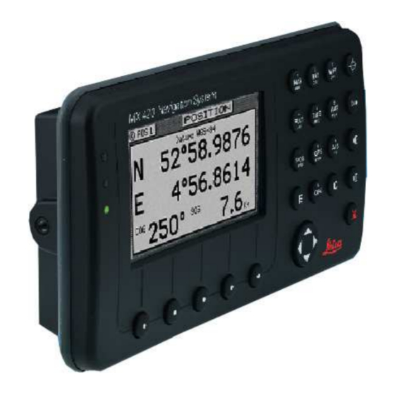
Page 21: Keypad & Display Description
Operator’s Manual Keypad & Display Description Keypad & Display Description Traffic Display Function Keys Lights R T E N A V W P T P L O T A U X T I D E P O S G P S A I S C F G 6289-01A.400... -
Page 22: Differential Gps Traffic Light Operation
Keypad & Display Description Operator’s Manual Differential GPS Traffic Light Operation: Red Flashing Not tracking satellites (no position update). This is normal for the first 2 minutes or so when turning the unit on. The very first time you turn the unit on, or if the memory is reset or lost, this condition is also normal. -
Page 23: Yellow Solid
Operator’s Manual Keypad & Display Description Yellow Solid DGPS position update with poor HDOP value. You may see this from time to time during normal operation. It usually occurs when you are tracking 3, 4, or 5 satellites, and the satellites have poor geometry relative to your position. -
Page 24: Yellow Solid
Keypad & Display Description Operator’s Manual minutes after changing to Red Solid to collect an almanac from the satellites, regardless of whether a position update has been calculated or not. This is also a normal indication if the HDOP is greater than 10. The HDOP value can be read in the GPS function screens. -
Page 25: The Softkeys
Operator’s Manual Keypad & Display Description With the exception of a portion of the PLOT and MOB screens which use two softkeys to change the view scale, all of the screens require that you press the E (Edit Mode) function key before you are allowed to change data on the screen. -
Page 26: Goto
Keypad & Display Description Operator’s Manual capable of performing this function from a remote contact closure in- put via Cable B (MOB/Event) wire. Refer to the Installation & Service Manual for interface instructions. GOTO This function key allows you to quickly create a route from your present position to one other waypoint. -
Page 27: Man Over Board (Mob)
To cancel a MOB condition, make sure you are in the MOB Plot screen. Press the E function key, then select the Cancel MOB softkey. This MX420 receiver is also capable of performing the MOB function from a remote contact closure. If the contact closure is made for less... -
Page 28: E E (Edit)
Navigate Operator’s Manual than 2 seconds, the input is registered as a Mark Position. If the con- tact closure is made for more than 2 seconds, the input is registered as a MOB Position. Refer to the Installation & Service Manual for inter- face instructions. - Page 29 Operator’s Manual Navigate when you are in the edit mode. You will find that they are most often used in the RTE, WPT, and CFG screens, but they are used in other screens as well. If you are trying to enter text, simply locate the desired letter and press the appropriate key repeatedly until the appropriate letter or number appears.
-
Page 30: Ais
Note: The AIS display key is not functional in the MX420/2 and MX420/8 mod- els. This is a special key that is active only in the MX420/AIS or MKD models. Non-AIS models will show the message “AIS Not Available on this Version”... -
Page 31: Navigate
Operator’s Manual Navigate Navigate There are four basic NAV screens. NAV4 only provides data if appro- priate sensors (e.g. wind speed/direction logs, NMEA compass, etc.) are interfaced and activated on the CDU. The NAV functions are highly interactive with the RTE1 screen, and a number of CFG menu selec- tions. -
Page 32: Dead Reckoning
CDU to do exactly what you want it to. Dead Reckoning The MX420 CDU is capable of Dead Reckoning (DR) calculation when appropriate compass/heading and speed log sensors are connected and activated. Refer to the NAV4 and CFG sections of this document. - Page 33 Operator’s Manual Navigate represents the bow of the boat. Icons on the screen are always related to this object. The two dash lines extending from the bottom of the screen towards the center of the screen represent your cross-track error limits. The dotted line extending from the bow of the boat icon represents your course line.
- Page 34 Navigate Operator’s Manual you to customize the information presented. View - allows you to adjust the display for a Close (zoomed-in) or a Far (zoomed-out) representation of your route. Show Waypoints - allows you to turn waypoints which are not part of the active route on and off.
-
Page 35: Nav2 - Basic Steering Information
Operator’s Manual Navigate NAV2 - Basic Steering Information Navigate screen 2 provides the bearing (BRG) and range (RNG) to the waypoint you are approaching in large easily viewed characters. Be- low these, you will see your actual Course Over Ground (COG) and Speed Over Ground (SOG). -
Page 36: Nav 3 - Expanded Navigation Information
Navigate Operator’s Manual From time to time, you might drift off course and decide not to return to your original course line. If you drift outside of your cross-track error limit, you can reset your course line from your present position to the waypoint by pressing the E key and selecting Reset XTE from the display. -
Page 37: Nav4 - Sensor Input Navigation
Operator’s Manual Navigate You will find the right hand window to be a helpful tool. In addition to identifying the waypoint you are currently approaching, it identifies the waypoint at the end of the next leg. The really unique feature of this screen is the graphical representation of your actual course line approach angle relative to the next leg of your course. - Page 38 Navigate Operator’s Manual records may contain depth information. This provides you the ca- pability of knowing the depth source exactly. Log - Sets the input port number, sensor type (pulse or NMEA 0183), alarms, and a correction factor (if needed). Set &...
- Page 39 Operator’s Manual Navigate lated by the MX421 smart GPS antenna), Heading (HDG, your NMEA 0183 compass input), and Heading To Steer (HTS) data on the left side of the window. HTS data is calculated by considering your Heading, minus COG and adding BRG to the waypoint. In doing so, the soft- ware considers any Set to be included in the HDG value.
- Page 40 Navigate Operator’s Manual Below this information, you will find your Set and Drift data, which is calculated using GPS and your compass and speed sensor inputs. Reset XTE and Skip Waypoint, described at the end of NAV2, is also available in NAV4. The window on the right displays depth information coming from the depth sounder unit using the NMEA 0183 record of DPT, DBS, DBT, or DBK.
-
Page 41: Route
Operator’s Manual Route Route There are two RTE screens. The NAV functions are highly interactive with the RTE1 screen. The RTE2 screen allows you to create a pool of predetermined routes that you might use often, so you need only create the route one time. -
Page 42: Rte1 - The Active Route
Route Operator’s Manual main intact in the RTE2 screen. The following CFG1 menus directly impact the RTE functions: Navigation - sets a variety of important functions and alarms. Rhumb line or Great Circle navigation Range units: nautical miles, nautical miles and meters (when under 1,000 meters), nautical miles and feet (when under 1,000 feet), statute miles, statute miles and meters (when under 1,000 meters), statute miles and feet (when under 1,000 feet), kilo-... -
Page 43: Creating A Route Using The Goto Key
Operator’s Manual Route Creating a Route Using the GOTO Key: Using the GOTO function key is the fastest way to create a single leg route. Using this method will cause the existing active route to be erased and overwritten with the new position you define. 1. - Page 44 Route Operator’s Manual Lat. Lon. - allows you to define a coordinate and description, which is also stored at the next available waypoint location in the Waypoint Bank. Once the coordinates are defined, press the E key to copy the waypoint to the active route. Bearing Range - allows you to define a coordinate by specifying the bearing and range from your present position, which is also stored at the next available waypoint location in the...
- Page 45 Operator’s Manual Route International characters are available by selecting the associated function key. Refer to the Keypad & Display Description section at the front of the manual. If you decide you don’t want to continue with this function, press the Escape softkey, then press the E key. Make another function key selection (e.g.
-
Page 46: Erasing An Existing Route
Route Operator’s Manual Below Waypoint 0 is the waypoint you defined in the GOTO function. Notice that this information is in standard video, black characters on a white background, and that an ETA time is displayed in the same posi- tion as the waypoint passed time in Waypoint 0. -
Page 47: Creating A Multi-Waypoint Active Route
Operator’s Manual Route Creating a Multi-Waypoint Active Route There are four methods to create a multi-waypoint route: Insert By Number - allows you to type in or scroll through in numerical order using the cursor key, waypoints that you previ- ously stored in the Waypoint Bank (see WPT later in this manual). -
Page 48: Insert By Number
Route Operator’s Manual Insert By Number The following example assumes RTE1 is empty. Follow the directions in the Erasing an Existing Route section to start with an empty route if you have waypoints in the RTE1 screen. 1. Select the RTE key until the RTE1 screen is displayed. 2. -
Page 49: Choose In Bank
Operator’s Manual Route Choose in Bank The following example assumes RTE1 is empty. Follow the directions in the Erasing an Existing Route section to start with an empty route if you have waypoints in the RTE1 screen. 1. Select the RTE key until the RTE1 screen is displayed. 2. -
Page 50: Insert New Waypoint
Route Operator’s Manual 7. When you are finished, press the Done softkey to get back to the main menu. 8. You can then choose to select another waypoint using the same method, select Escape to go back one level and use another method to enter waypoints, or select Done do go back to the main menu. -
Page 51: Insert Route
Operator’s Manual Route 6. When the information is correct, press the Done softkey. 7. You can then choose to enter another waypoint using the same method, select Escape to go back one level and use another method to enter waypoints, or select Done to go back to the main menu. 8. -
Page 52: Scrolling
Route Operator’s Manual Maneuvering Within the Route Scrolling You can use the cursor key to scroll up and down the active route. You will probably want to do this when you update your log book to indi- cate when you passed a given waypoint, or when you want to know the ETA to a waypoint other than the one you are currently traveling towards. -
Page 53: Inserting Waypoints Or Routes Into An Existing Route
Operator’s Manual Route Use the up ( ) softkey to unpass or the down ( ) softkey to pass waypoints in the route until the waypoint marked by the cursor is displayed with white characters on a black background (Daylight dis- play, see CFG1 Lighting). - Page 54 Route Operator’s Manual 5. Press the E key to end editing. There is one special way to add a waypoint to the active route using the Plotter display. This method adds the waypoint between your present position and the next waypoint in your active route. 1.
-
Page 55: Reversing The Active Route
Operator’s Manual Route Reversing the Active Route Once you get to your final destination, you might want to follow the same route home. To quickly accomplish this, simply use the Reverse Direct softkey from the main RTE1 menu. 1. Select the RTE key until the RTE1 screen is displayed. 2. -
Page 56: Eta Setup
Route Operator’s Manual ETA Setup If you choose to use this function, it is probably better to operate the unit in UTC time mode if you are going to cross one or more time zones. Note that the time entered uses the offset to UTC applied in the CFG1 Time display. -
Page 57: Sog Based On Arrival Date & Time
Operator’s Manual Route SOG Based on Arrival Date & Time: 5. Enter the arrival time and date. Be sure to enter the date as day, month, year, as indicated on the screen. 6. Press the Done softkey. In this mode, the actual SOG is compared to the required SOG to meet the specified arrival date and time. -
Page 58: Rte2 - The Route Bank
Route Operator’s Manual RTE2 - The Route Bank The Route Bank is a convenient place for you to preprogram segments of a long voyage, or to program routes that you follow over and over again. Creating routes for the Route Bank uses the same methods as the Active Route with a few exceptions: you can’t use the GOTO key, and you can’t use the Plotter screen. - Page 59 Operator’s Manual Route softkey. You can enter any name, number or symbol you want this route to be identified by. 6. Press the Done softkey when you are finished editing the name. Note: It is a good idea at this point to select Lock Route so that way you won’t accidentally erase the route sometime in the future.
-
Page 60: Waypoint
Waypoint Operator’s Manual Waypoint The Waypoint Bank (WPT) is a single list of up to 2,000 waypoints that you store for use in the routes you create. It also stores special coordinates and time, through the use of the Mark or Event function key or external input, or the MOB function key or external input. -
Page 61: Creating And Editing Waypoints
Operator’s Manual Waypoint For example, if you are looking for the LA HARBOR ENTRANCE and you enter HAR, the screen will display all waypoints with these three characters in this exact order. Creating and Editing Waypoints When editing a waypoint, you are always prompted to select the ap- propriate datum. - Page 62 Waypoint Operator’s Manual 3. Make New WPT 4a. Use WGS-84 Datum 4b. Use Datum Other 4c. Create a new WPT Based Select Than WGS-84 on a Range & Bearing Lat/Lon (W84) Select from an existing WPT Lat/Lon Datum Select Range Bearing Select desired datum Enter desired range from displayed list.
- Page 63 Operator’s Manual Waypoint Lat/Lon (W84) - allows you to enter coordinates in the WGS 84 datum. This choice takes you directly into the coordinate input screen. Go to step 5. Lat/Lon Datum - allows you to choose a datum (see the list in the screen sample above) from the more than 110 available Datums.
- Page 64 Waypoint Operator’s Manual light the desired datum and press the Select softkey. Refer to Ap- pendix A - Datum List for a complete list of datums and their WGS 84 offset. 5. Enter the appropriate coordinates using the cursor key and nu- meric keypad.
- Page 65 Operator’s Manual Waypoint The following international characters are supported by cycling through the standard letter function key: ABC = Ä, Å, Æ, À, Ç DEF = É, È GHI = Í MNO = Ñ, Ó, Ö STU = Ú, Ü Press the CFG key when in the edit mode to cycle through these additional characters: ‘...
-
Page 66: Waypoint Lock/Unlock
Waypoint Operator’s Manual 9. Then press the E function key to end editing. You can press the E key when you finish editing a waypoint. This is treated the same as pressing the Done softkey. Pressing Done allows you to continue editing and entering other waypoints. Waypoint Lock/Unlock Locking a waypoint forces the user to consciously unlock the waypoint before it can be modified and prevents the waypoint from being over-... -
Page 67: To Unlock A Waypoint
Operator’s Manual Waypoint 4. Press the Lock this WPT softkey. 5. Press the E key. To Unlock a Waypoint 1. Select the WPT key until the WPT1 screen is displayed. 2. Move the cursor to the desired waypoint. 3. Press the E key. 4. -
Page 68: To Unlock All Waypoints
Waypoint Operator’s Manual 6. Press the Lock all WPT softkey. 7. Press the E key. To Unlock all Waypoints 1. Select the WPT key until the WPT1 screen is displayed. 2. Move the cursor to the desired waypoint. 3. Press the E key. 4. - Page 69 Operator’s Manual Waypoint Lock/Unlock section for a step by step procedure, and then return to this section. To remove a waypoint: 1. Select the WPT key until the WPT1 screen is displayed. 2. Move the cursor to the desired waypoint. 3.
-
Page 70: Moving Waypoints
Waypoint Operator’s Manual 6. Press the E key. Moving waypoints This feature allows you to create a range of waypoints within a par- ticular area. For example, you could put all of the waypoints for fishing spots near Catalina Island in the range of 500 to 530, all the waypoints for Cabo San Lucas in the range of 575 to 600, etc. -
Page 71: Downloading Waypoints & Routes To Other Devices
Operator’s Manual Waypoint 6. Enter the waypoint number where you want the first waypoint moved to in Destination WPT Number. If the destination waypoint number is already being used, you will be prompted to either overwrite the first waypoint (Yes) and each subsequent waypoint that is to be overwritten, confirming each waypoint one at a time, overwrite all the waypoints (Yes To All), not overwrite any waypoints (No);... -
Page 72: Rnn - Routes
Waypoint Operator’s Manual CFG1 NMEA Out screens for the identifier given below. The CDU outputs these sentences in the following format: Rnn - Routes: Waypoint identifiers, listed in order with starting waypoint first, for route number “nn”. The active route in the CDU is always route zero, but in the Rnn sentence the route number can be transmitted as either route 00 or 01. -
Page 73: Wpl - Waypoint Location - Nmea 0183 Standard
Operator’s Manual Waypoint Message mode: c = complete route, all waypoints, w = work- ing , 1 listed waypoint is ‘FROM’, 2 is ‘TO’ and remaining are the rest. c/w can be set to c or w (default w). Route identifier, always 00 (Active Route only). 6 - 16: Waypoint identifiers, (less than 11 waypoints may be in the message). -
Page 74: Downloading Waypoints To A Personal Computer
Waypoint Operator’s Manual route. The CFG1 NMEA out WPL has a special “Send All” option. Selecting this feature will send all the waypoints in the Waypoint Bank once independent of the WPL sentence setup as ON or OFF. This format does not strictly conform to the NMEA 0183 standard, and may not work with all equipment. - Page 75 Operator’s Manual Waypoint ficient to get the job done. Unfortunately, Hyperterminal in Windows 95 doesn’t provide as simple a terminal emulation program as Win- dows 3.11, and we have found it unreliable. We suggest that a third party terminal program be used with Windows 95. Using Windows Terminal, do the following (from the Program Man- ager): 1.
-
Page 76: Uploading Waypoints From Other Devices
Waypoint Operator’s Manual 1 stop bit Parity - none Flow Control - none Connector - Com1 (or Com2, depending where the external interface is) Parity Check - blank Carrier Detect - blank 16. Click on the Transfers menu. 17. Double click on the CDU Text File menu item and make the follow- ing settings. -
Page 77: Uploading Waypoints From A Personal Computer
Operator’s Manual Waypoint Uploading Waypoints from a Personal Computer You can use any terminal or communications program to download or upload waypoints and routes to or from the CDU and a PC. Set the PC to: 4800 baud 8 bits 1 stop bit no parity no flow control... - Page 78 Waypoint Operator’s Manual 8. On the computer, double click on the Accessories icon. 9. Double click on the Terminal icon. 10. Click on the Settings menu. 11. Double click on the Communications menu item and make the fol- lowing settings: 4800 baud 8 data bits 1 stop bit...
-
Page 79: Mark Or Event
Operator’s Manual Waypoint Mark or Event This function key stores your present position, date and time at the next available waypoint location in the Waypoint Bank. A window pops up on the screen to confirm your key depression, and to tell you where the Mark position is being stored. -
Page 80: Goto
GOTO Operator’s Manual GOTO Using the GOTO function key is the fastest way to create a single leg route. This method will cause the existing active route to be erased and overwritten with the new position you define. 1. From any screen press the GOTO key. 2. - Page 81 Operator’s Manual GOTO 4. To activate the GOTO waypoint, press the E key. A warning is briefly displayed indicating that the active route will be replaced with the GOTO route. If you decide you don’t want to continue with this function, press the Escape softkey, then select another function key (e.g.
- Page 82 GOTO Operator’s Manual see in the navigate screens between your present position and your next waypoint during normal navigation. Below Waypoint 0 is the waypoint you defined in the GOTO function. Notice that this information is in standard video, black characters on a white background, and that an ETA time is displayed in the same posi- tion as the waypoint passed time in Waypoint 0.
-
Page 83: Plot
Operator’s Manual Plot Plot There are two PLOT screens available in the basic MX420 navigator models. The RTE1 and WPT functions are highly interactive with the PLOT screens. The primary difference between the PLOT1 and PLOT2 screens is the point of reference. The PLOT1 screen displays graphic information around the boat at your present position. - Page 84 Plot Operator’s Manual Cross-track error limits COG / SOG Filter Settings. Take a quick look at both screens. They both have a graphical area to the right, and a text data area to the left. The bottom left softkey is the Zoom-In softkey; the second softkey from the left is the Zoom-Out softkey.
-
Page 85: Plot 1 - Relative To Boat
Operator’s Manual Plot PLOT 1 - Relative to Boat The information in PLOT1 is always relative to your present position. The boat always remains in the center of the screen and the bearing and range are always from your present position to the next waypoint identified in RTE1. -
Page 86: Customizing The Display
Plot Operator’s Manual coordinates and datum in which it is stored, and your present bearing and range to this location (as opposed to the waypoint you are travel- ing towards in your active route). If you want to alter your present course, you can do it very quickly from here. - Page 87 Operator’s Manual Plot Press the Display Options softkey. The following choices are available: Show Boat - Yes is the default condition, which places the boat icon in the middle of the screen. No places the boat in a Compass Rose in the upper right corner of the screen (see the diagram be- low), where your direction is indicated by the boat in the Compass Rose.
- Page 88 Plot Operator’s Manual only displayed for the leg of the course you are presently on. If you reset your cross-track error, these lines are redrawn to reflect the course change (see NAV2). No causes the cross-track error lines not to be displayed. Note that these lines can only be displayed in Rhumb Line navigation mode (see CFG1 Navigation).
- Page 89 Operator’s Manual Plot Press Erase Now to confirm your action. Press Escape to return the previous screen without erasing or E to abort this process. Selecting Record Track allows you to define how your course is saved. Choosing not to save your track may free the processor up to run other functions a little bit faster;...
-
Page 90: Plot 2 - Relative To Marker
PLOT3 - AIS Plotter Display This plot screen is available only in MX420/AIS and MKD CDUs. It is accessed by pressing the PLOT key the third time. It displays a graphic picture of the area surrounding your vessel. In this display any AIS equipped vessel that is within the range will be shown. -
Page 91: Plot Screen Use Examples
Operator’s Manual Plot Plot Screen Use Examples Station Keeping There may be a time when you want to maintain your position at a given location in open water. Some applications for this need may be: Staying over a dive wreck. Staying over a fishing hole. -
Page 92: Grid Search
Man Over Board Operator’s Manual approach. Note for the plot example above, we turned off the cross- track error lines, the active route, and track saving to keep the screen from getting cluttered while drifting. Grid Search If you are attempting to search a given area, you can use the PLOT2 screen to define a known coordinate in your search pattern, then use both the PLOT1 and PLOT2 screens to view your progress and help maintain your proper separation. - Page 93 Operator’s Manual Man Over Board The MOB position, date and time are stored in the next vacant waypoint memory of the Waypoint Bank for future reference (e.g. log book en- tries). An MOB symbol is used to denote an MOB waypoint. Note: The range and bearing in the PLOT, NAV, and MOB screens all reflect your bearing and range back to the MOB position, not...
-
Page 94: Remote Mob
Remote MOB The MX420/8 is capable of performing the MOB function from a re- mote contact closure input via Cable B “MOB/Event” wire shared with the Mark input. If the contact closure is made for less than 2 seconds, the input is registered as a Mark Position. -
Page 95: Tide
The following CFG1 menus directly impact the TIDE functions: Depth - sets the measurement units in meters, feet, or fathoms. Note: The Tide function is not active in the MX420/AIS Basic model without the MX421 antenna. TIDE1 - Current Tide Display This screen provides the current tide conditions for the tide constants indicated in the upper left hand corner. -
Page 96: Tide2 - Tide Table Port List
Tide Operator’s Manual the marker changes to a + sign. The marker will remain at the manually positioned mark until you either press one of the manual marker con- trol softkeys, or until you press the Marker to Now softkey - which returns the marker to automatic mode (indicated by the clock marker). - Page 97 Operator’s Manual Tide This is a three volume set of tide tables, divided as follows: Volume 1 Volume 2 Volume 3 Volume 3 6322-01A.600 The display provides the required tide table document name and sec- tion (Admiralty Tide Tables, Part III) under the Help softkey when in the edit mode as an added aid to help you identify the proper reference material.
-
Page 98: Adding A Port
Tide Operator’s Manual Adding a Port To add a port to the list, first locate it in Part III of the tide table book, then align the cursor with Add port to the Port List and press E. The Zone in the upper left corner refers to the time zone offset to UTC. Use the name given in the tide table for the name given in the Place portion of the screen. -
Page 99: Auxiliary
Auxiliary Operator’s Manual Auxiliary There are seven Auxiliary screens described in this section: AUX1 - Alarm Log AUX2 - Speed Graph AUX3 - Not Used AUX4 - Sun Almanac AUX5 - Moon Phases AUX6 - Batteries AUX7 - Unit Information AUX1 - Alarm Log All alarms are registered in this screen, whether or not they have been corrected, until the log is erased or the log is full. - Page 100 You can enter another date or location of interest by pressing the E key, and editing the appropriate date and/or place. Note: The AUX 4 function is not active in the MX420/AIS Basic model without the MX421 antenna.
-
Page 101: Aux6 - Batteries
You change the year displayed by pressing the up or down cursor keys. Note: The AUX 5 function is not active in the MX420/AIS Basic model without the MX421 antenna. AUX6 - Batteries The supply voltage indicates the approximate power being applied to the CDU. -
Page 102: Aux7 -Unit Information
To activate the screen, press the left most softkey three (3) times. Additional information in the Software window will be displayed. MX420/2 AUX7 Screens This also activates several engineering screens (the same as turning Engineering Display to Yes in CFG1 Operation). Refer to Appendix C - Engineering Mode for more details. -
Page 103: Position
Position Operator’s Manual Position There are three POS screens in the CDU. The POS functions are highly interactive with a number of CFG1 menu selections. The following CFG1 menus directly impact the POS functions: COG SOG - sets the filtering time for the displayed values. Datum - sets the reference datum for your present position. -
Page 104: Utm
UTM coordinates. User GRID User defined grids is an optional feature of the MX420. When enabled you can set the receiver to provide Easting and Northing position data based on a local grid. The grid function is set up in the CFG1 Position screen. -
Page 105: Pos2 - Position, Altitude, Magnetic Variation, & Time
Position Operator’s Manual POS2 - Position, Altitude, Magnetic Variation, & Time This screen is divided into three windows. The upper left window provides your position coordinates, the antenna altitude (above Mean Sea Level - MSL), altitude mode (2D or 3D), the magnetic variation (Variation) for your present position, and the present datum in use for calculating your position. - Page 106 Position Operator’s Manual The lower left window is also the same as POS2 and displays your course and speed over ground. If the degree symbol has a small c under it, this indicates that the magnetic variation and compass devia- tion table are being calculated and displayed.
-
Page 107: Gps
Operator’s Manual Several GPS and DGPS screens are available under the GPS function key. The GPS/DGPS functions are highly interactive with these CFG1 menu selections: GPS - sets the lowest elevation at which a satellite will be tracked. DGPS - sets the internal beacon receiver to Auto, DGPS only, or Off. - Page 108 Operator’s Manual number and the columns represent the 1’s digit of the ID number. The satellite system consists of up to 32 ID numbers. The ID numbers are called PseudoRandom Numbers. To find a particular satellite ID, for example PRN 24, go down the left hand column and locate the 10’s digit (2- in this case).
- Page 109 GPS5 - RAIM Status Screen (for RAIM Enabled Models Only) RAIM (Receiver Autonomous Integrity Monitoring) is an optional feature that can be enabled in the MX420 CDU. The RAIM feature is mandatory for IMO compliant vessels. It alerts the operator that a condition may exists in the GPS positioning solution that reduces the desired accuracy of the ship’s position.
- Page 110 6. Scroll down to “Accuracy Rng 10-100m: 100” to change the range. Otherwise you may skip this step. 100 meters is the default value. Note: The GPS5 RAIM Status screen is available in MX420 models with pro- gram version 2.0 and using the MX521 or MX525 antenna sensors.
-
Page 111: Gps6 - Dgps Status
The right hand win- dow displays all the corrections that are being received. Shown below are two GPS6 screens, the left showing the MX420/2 DGPS status screen while the right showing the MX420/8 screen. Note the slight difference in the amount of information available between the two models. - Page 112 Operator’s Manual Use the cursor key to move down the screen again and program the frequency you desire. The receiver will automatically update the Sta- tion ID. If the beacon station is transmitting its location, the receiver will calculate the distance between the reference station and the re- ceiver, otherwise this will be blank.
-
Page 113: Gps7 - Dgps Messages
These messages may contain information regarding operational problems and status or any scheduled equipment maintenance of beacon stations operating within the general area. Note: The GPS screen is not active in the MX420/AIS model without the MX421 antenna. Version 2.0... -
Page 114: Configuration
This is an AIS setup menu used for configuring the vessel’s name, MMSI #, IMO #, transponder radio settings, associated communication mode and data output selections. See Appendix A for more details. This item is only available in MX420/8 models with the AIS feature option enabled. AIS Voyage... -
Page 115: Anchor - Anchor Watch Alarm
Operator’s Manual Configuration anchor alarm in this screen to go from Off to On. Likewise, if you turn the anchor alarm from On to Off in this screen the Anchor screen will also match this one. Anchor - Anchor Watch Alarm This screen allows you to setup an anchor watch alarm and maximum drift radius after you drop the anchor. -
Page 116: Compass - External Compass Input & Magnetic Variation Table
Configuration Operator’s Manual Compass - External Compass Input & Magnetic Variation Table The receiver will accept a magnetic compass input using the NMEA 0183 data record of xxHDT, xxHDG, xxHDM, xxHCC, xxHCD, xxVHW, or any of the above. “xx” refers to the Talker Identifier as specified in the NMEA 0183 standard. -
Page 117: Datum - Current Position Calculation
Operator’s Manual Configuration Gyro: Set the constant Gyro Heading Offset (or bias) if any. Specify the input NMEA 0183 record for the Input Sentence. HDT, HDG, HDM, HCC, HCD, VHW, or Any. Datum - Current Position Calculation This screen controls which datum the receiver uses to display any position. -
Page 118: Depth - Nmea Input Control
NMEA 0183 data sentences when set to Yes. Data Input Port No. - Select the appropriate NMEA 0183 port that the sensor is connected to (Ports 1& 2 for MX420/2 or Ports 1,2, 5 through 10 for MX420/8). Ports 3 and 4 are reserved for the MX421 antenna controls. -
Page 119: Dgps - Dgps Configuration
Operator’s Manual Configuration activate. This alarm limit is enabled by the Shallow Alarm Active selection of Yes. Alarm If No Data - Allows you to receive an audible and visual alarm if NMEA 0183 data is not being received on the data port at regular intervals (typically every few seconds). - Page 120 Configuration Operator’s Manual Use this mode when maximum navigation coverage is more important than accuracy. Reverting to GPS mode will degrade the overall navigation results, but it is better than no naviga- tion results at all in most circumstances. DGPS Only - sets the receiver to only provide DGPS position fixes.
-
Page 121: Dr - Dead Reckoning
The default setting is No. When this selection is changed to Yes, one receiver is set to Master, the other receiver is set to Slave. The master unit can be either an MX420/8 CDU or MX420/2. These two units will share a common database and one antenna. Refer to Appendix E for more detailed information about the dual control setup and operation. - Page 122 The RAIM menu is available only in MX420 models where the RAIM feature is enabled. For more detailed information about RAIM, please refer to page 96 of this manual. Standard MX420 CDU will only show the Elevation mask and Anttena offset menu items.
-
Page 123: Init Pos - Initial Position Entry
Operator’s Manual Configuration Init Pos - Initial Position Entry This screen is provided to help the GPS receiver in the MX Marine antenna to get a faster first position fix. While the smart antenna is capable of computing its position without any user input, this feature can cause a position fix to occur several minutes earlier. -
Page 124: Language - Language Configuration
Configuration Operator’s Manual Language - Language Configuration The receiver supports 9 languages: English, Dutch, French, Finnish, German, Italian, Spanish, Swedish and Danish Press the E key. Use the cursor key to scroll down the list until you find the desired language. Press the E key again. The CFG menu list will sort the menu selections in alphabetical order based on the language selected. - Page 125 Operator’s Manual Configuration NMEA 0183 (VHW) Input Screen Pulse Input Screen NMEA Input: Data Input Port No. - Select the appropriate NMEA input port as determined by the hardware interface. Refer to the Installa- tion & Service Manual for wiring connections. Alarm If No Data - Causes an alarm to activate if data is not re- ceived on the port you defined within 10 seconds when Yes is selected (the default condition).
-
Page 126: Log Pulses - Gps Sog Log Pulse Output
200 pulses per nautical mile. Refer to the MX 420 Installation & Ser- vice Manual for the hardware interface from one of the NMEA output ports (NMEA 1 or 2 for the MX420/2 and NMEA 1, 2 or 5 through 10 for the MX420/8 models) -
Page 127: Navigation
Operator’s Manual Configuration The COM1 port of the PC must be connected to the RS-232 port of NMEA 2 of the CDU (refer to the Installation & Service Manual). Note: The message “Function is not active” will be shown when the WPT, RTE or TIDE keys are pressed when the MX480 chart mode is activated. - Page 128 Configuration Operator’s Manual Direction: Sets all displays which indicate direction to True or Compass. If you want the receiver to agree with your magnetic compass, select Compass. The receiver will automatically add or subtract the ap- propriate magnetic variation and deviation. Enter the compass de- viation table into the receiver in this screen.
- Page 129 Operator’s Manual Configuration waypoint by crossing the bisector line of an acute angle (providing you are within 0.2 NM of the waypoint) or an obtuse angle between your present course line and the next leg of your route. Manual: Passing the waypoint can only be accomplished by manually skip- ping a waypoint.
-
Page 130: Nmea Out 1 Through N* - Nmea 0183 Output Data Control
* The number of user NMEA ports available depends on the model of the CDU unit: MX420/2 Model - has two user NMEA ports available and one proprietary port (NMEA3) dedicated to the MX Marine smart antenna. MX420/8/AIS Model - has eight user NMEA ports available and two antenna ports (NMEA3 &... - Page 131 NMEA 0183 output sentences. MX 420/2 NMEA Out Menu MX420/8 & /AIS NMEA Out Menu Scroll down the list using the cursor key to the desired NMEA 0183 sen- tence. Use the Change softkey or right arrow key on the cursor to select On.
- Page 132 Configuration Operator’s Manual quire the checksum. The receiver provides you the option of turning the checksum on or off to provide flexibility in interfac- ing. Output Rate - maximum once per second, unless the Multi-Hertz option is installed. Refer to the Total Load Is section which follows.
- Page 133 Operator’s Manual Configuration xxx loads the port by - The NMEA 0183 standard limits the port baud rate to 4800 bits per second. It is impossible to turn on every NMEA 0183 data record on one port in the receiver at a once per second output rate, due to the NMEA standard limi- tation.
- Page 134 Configuration Operator’s Manual WPL - Waypoint Location Data Record: The receiver outputs all of the waypoints in the active route. If you want to output the complete Waypoint Bank, simply press the Send All softkey from the NMEA WPL screen. The WPL record, as defined by the NMEA 0183 standard, technically does not allow the output of waypoint descrip- tions when interfacing to other devices such as Chart Plotters.
-
Page 135: Other Special Cases Affecting Nmea 0183 Records
Operator’s Manual Configuration Other Special Cases Affecting NMEA 0183 Records: BWC, BWR, APA, APB, RMB, RMC, and Man Over Board (MOB): During the period when the Man Over Board function is activated, NMEA 0183 records which contain bearing and range data, such as those identified above (but not limited to these), will reflect the bearing and range back to the MOB position until the MOB func- tion is canceled. -
Page 136: Operation - General Setup And Control Settings
Configuration Operator’s Manual Operation - General Setup and Control Settings This screen controls a few basic operating settings: Remember Display: When set to Yes (default), the receiver remem- bers the Page Number or screen you viewed the last time you used a particular function. -
Page 137: Organizer - Automated Message Reminders
Operator’s Manual Configuration Engineering Display: This enables an expanded series of display screens in some of the functions. In general, these screens are used by the technician during troubleshooting or by MX Marine engineers during development testing. Screens which are relevant for troubleshooting are described in Appendix D of this manual. -
Page 138: Position - Positioning Reference, Mode, & Alarm Control
Configuration Operator’s Manual The setup is straight forward. Use the Change softkey to increment forward through the available choices. Use the Go Back softkey to increment backward through the available choices. You can also use the left and right cursor keys to accomplish these same operations. Enter text the same as you do for the waypoints and routes. - Page 139 Operator’s Manual Configuration Likewise, when you select Loran C, you can set the Chain yourself (Man), or let the receiver calculate the chain for you (Auto, default). Alarm For High HDOP: This allows the receiver to create an alarm for HDOP values which rise above a number that you determine.
-
Page 140: Printout 2 - Printer Output Control
The printer output is simple ASCII text designed to operate on any serial line printer, including narrow column printers. The receiver has two print formats, namely: Full or Brief. A sample of the Full printer output format is given below: MX Marine MX420/8 Navigator ==================================== 20:42:41 12 Apr 2002... - Page 141 Operator’s Manual Configuration Here is a sample of the Brief format without an active route: MX Marine MX420/8 Navigator ==================================== 21:24:00 12 Apr 2002 POS Mode : DGPS 3D Datum:W84 POS: N 33 48.5124 W 118 21.0213 COG: 152T SOG: 0.1 Kn...
-
Page 142: Rot (Rate Of Turn)
ROT (Rate of Turn) The ROT configuration menu is only available in MX420 models with the AIS or MKD feature enabled. It is not available in standard MX420 models. The “ROT connected” mode can be toggled to YES or NO, by pressing the E key and then pressing the ‘Change’... -
Page 143: Serial I/O
Serial I/O This menu provides a means to verify the status and baud rate settings of all the NMEA ports. Note that the NMEA port 3 (MX420/2) and NMEA ports 3 & 4 (MX420/8) are reserved for the MX421 GPS and Beacon receiver interface. -
Page 144: Wind
VWR sentence. Data Input Port: 1 (default) or 2 for MX420/2 1 (default) or 2, 5, 6, 7, 8, 9 or 10 for MX420/8 Note: Ports 3 & 4 are reserved for the MX421 GPS and Beacon controls and will not be selected. -
Page 145: Wpt & Rte Input - Uploading Waypoints Into The Receiver
Operator’s Manual Configuration Alarm If No Data: Allows you to receive an audible and visual alarm if NMEA 0183 data is not being received on the data port at regular intervals (typically every few seconds). The available choices are Yes (default) or No. AWA Offset: Allows you to input a constant angle correction value. -
Page 146: Appendix A - Automatic Identification System (Ais)
Automatic Identification System Operator's Manual Appendix A - Automatic Identification System (AIS) Introduction AIS is a shipborne broadcast transponder system in which ships continually trans- mit their ID, position, course, speed and other data to all other nearby ships and shoreside authorities on a common VHF radio channel. - Page 147 Operator’s Manual Automatic Identification System Position and other data are fed automatically from the ship’s sensors into the AIS system, where the data is formatted and transmitted in a short data burst on a dedicated VHF channel. When received on the other ships, the data is decoded and displayed for the officer of the watch, who can view AIS reports from all other AIS-equipped ships within range in graphic and text format.
- Page 148 Automatic Identification System Operator’s Manual Coastal Surveillance In coastal waters, shoreside authorities may establish automated AIS stations to monitor the movement of vessels through the area. These stations may simply monitor AIS transmissions from passing ships, or may actively poll vessels via the AIS channels, requesting data such as identification, destination, ETA, type of cargo and other information.
- Page 149 Operator’s Manual Automatic Identifaction System even when the radar picture is degraded by heavy precipitation or other interfer- ence. The AIS channels can be used to transmit port data, pilotage, berth assignments, shipping agency information, tides and currents, notices to mariners and other information from shore to ship, as well as ship-to-ship and ship-to-shore AIS reports.
- Page 150 Automatic Identification System Operator’s Manual AIS Communications Scheme AIS messages must be updated and retransmitted every few seconds at a mini- mum, since the usefulness of the data decays rapidly as a function of time. To accommodate this high update requirement, AIS utilizes a unique self-organizing time-division multiple access (SOTDMA) data communications scheme, which uses the precise timing data in the GPS signals to synchronize multiple data transmissions from many users on a single narrowband channel.
- Page 151 Operator’s Manual Automatic Identifaction System stations currently on the network. When a ship first enters the cell of another ship, it takes an unoccupied timeslot. The AIS stations continually synchronize their slot selections with each other. Timeslots and time-out periods are selected on a randomized basis. When a station changes its slot assignment, it announces to all other stations on the channel its new location and time-out for that location.
- Page 152 Automatic Identification System Operator’s Manual Shift Keying) modulation technique, which is specified in ITU Recommendation M.1371.1. The International Telecommunications Union (ITU) has designated two dedicated frequencies for AIS. They are 161.975 MHz (marine band channel 87B) and 162.025 MHz (channel 88B). In some parts of the world, such as the United States, where these frequencies may not be available for AIS, other chan- nels may be designated.
- Page 153 Operator’s Manual Automatic Identifaction System Voyage related data Ship’s draft Hazardous cargo (type) Destination and ETA (at master’s discretion) Safety-related messages As needed Dynamic information is derived from interfaces with the ship’s GPS and other sensors. Static information is programmed into the unit at commissioning. Voy- age-related data is entered manually by the master through a password-pro- tected routine.
- Page 154 MX420/AIS Navigation System The MX420/AIS Basic provides control and display interface to the MX531 AIS tran- sponder and other navigation sensors, while the MX420/AIS does all this and also pro- vides complete DGPS navigation functions. The MX420/AIS incorporates: • a Control and Display Unit (CDU) for GPS, DGPS and AIS (MX420/AIS) •...
-
Page 155: Ais System Setup
Operator’s Manual Automatic Identifaction System AIS System Setup Prior to using the MX420/AIS CDU, it is necessary to configure the AIS menus under the CFG key, namely: • AIS Config • AIS Static • AIS Voyage To access the AIS configuration setups, follow the procedure below. -
Page 156: Configuring The Ais Static Setup
Automatic Identification System Operator’s Manual Configuring the AIS Static Setup The AIS Static Setup contains both the ship’s static data and AIS transponder configuration. This setup must be done after installation or at any time changes are made to the ship’s AIS transponder unit. It is important to note that critical AIS static setup items (such as MMSI, IMO, Ship name &... - Page 157 Automatic Identifaction System Note: A total of 37 lines are available under the AIS Static menu. If only 10 lines are listed, the MX420 may not be communicating with the transponder. Verify that the “AIS Connected” value is set to YES and the correct transponder type is selected.
- Page 158 AUTO, Manual or Off. In Manual mode, the user is prompted to reply to the Long-Range system when interro- gated. In Auto mode, the MX420/AIS automatically sends a reply when interrogated. In Ext. Appl (External Application) mode, the MX420/AIS passes the request onto the high-speed ports (ECDIS &...
- Page 159 MX421 GPS an- tenna used by the MX420/AIS unit. The sum of A + B is the length of the ship in meters, and the sum of C + D is the width of the ship in meters.
- Page 160 Automatic Identification System Operator’s Manual Ext GPS Ant A, B, C, D: Specify the position offset of the external GPS antenna (similar to the Int. GPS Ant A,B,C,D). AIS GPS Ant A, B, C, D: Specify the position offset of the GPS antenna used in the MX423 AIS transponder (administrator password required).
-
Page 161: Configuring The Ais Voyage
12. At the end of editing, press the E key to exit. Configuring the AIS Voyage Information about the ship’s destination, ETA time and date, number of passengers/crew and type of vessel are entered in the MX420 for each voyage or whenever needed. AIS Voyage Parameter Descriptions: Nav Stat - Press the softkey to select specific status. - Page 162 Ship is anchored or moored MX420 not communicating with transponder Note: The displayed icons located on the top-right corner of the screen is set to blink off and on every 3 seconds to allow the operator to see what is behind it and is not considered an alarm condition.
- Page 163 Operator’s Manual Automatic Identifaction System Table A.2 ID Numbers Used in AIS Identifier No. Special craft Pilot Vessel Search and rescue vessel Tugs Port tenders Vessels with anti-pollution facilities or equipment Law enforcement vessels Spare – for assignments to local vessel Spare –...
-
Page 164: Ais Function Key
Automatic Identification System Operator’s Manual AIS Function Key Several AIS display pages are available under the AIS key. Pressing the AIS key repeatedly will scroll through the following AIS screens (paging can also be done by using the left or right arrow keys after pressing the AIS key), namely: AIS1 - OWN SHIP DATA AIS2 - REMOTE SHIP LIST AIS3 - RX SAFETY MSGS... - Page 165 GPS Source: Source of the GPS information in use. The choices are Primary (MX421, MX521 or MX525 smart GPS sensors), Secondary (exter- nal GPS attached to the MX420 CDU), and Backup (Transponder GPS). Lat/Lon: Position fix of the GPS in use.
-
Page 166: Ais 2 - Remote Ship List
Automatic Identification System Operator’s Manual AIS 2 - Remote Ship List This display shows a list of ships equipped with AIS transponders that are being tracked within VHF range. The list can be sorted by range from your location or by bearing. - Page 167 Operator’s Manual Automatic Identifaction System MMSI: Defines the unique vessel ID RNG: Range (meters) from your ship to the remote vessel BRG: Bearing (degrees) from your ship to the remote vessel NAME: Name of remote vessel Softkey Descriptions: - User can choose to have a list of MMSIs displayed in 15 degrees incre- ments.
-
Page 168: Ais 3 - Received (Rx) Safety Messages
AIS 3 - RECEIVED (RX) SAFETY MESSAGES This display stores all AIS safety messages broadcast by other AIS stations or messages addressed to your ship. The MX420/AIS will retain the last 100 messages received. You have the option to manually delete the message by pressing the softkey. -
Page 169: Ais 4 - Transmit (Tx) Safety Message
Operator’s Manual Automatic Identifaction System AIS 4 - TRANSMIT (TX) SAFETY MESSAGE This display allows you to write and send short text messages dealing with safety at sea and broadcast it to all AIS equipped vessels or address it to a specific station. Display Field Descriptions: OUTPUT CHNL - This field specifies which channel is to be used for sending the safety message. - Page 170 Datum List Operator’s Manual Softkey Descriptions: The softkeys can be displayed by pressing the E key first. - Each time this soft key is pressed, the transponder channel selection is changed. The following values are available: AUTO SELECT - transponder determines on which channel to broadcast the information CHANNEL A - broadcast on channel A only CHANNEL B - broadcast on channel B only...
-
Page 171: Ais 5 - Tx Safety List
Operator’s Manual Automatic Identifaction System AIS 5 - TX SAFETY LIST This display allows you to scroll through the safety messages you transmitted under the AIS 4 (TX SAFETY MSG) display. Display Field Description: Transmit Time - Time the message was transmitted Mode - Whether it was addressed or broadcast Message Field... -
Page 172: Ais 6 - Regional Areas
These parameters are stored in the memory bank of the AIS transponder and can be displayed in the MX420/AIS CDU. Up to eight regions can be stored by the transponder. The AIS constantly checks the stored region boundaries and com- pares it to its own position. - Page 173 - softkey used to display information for the previous region. - request new regional parameters from the transponder. Note: The MX420 will inform the operator if the zone size or delta Lat/Lon are too small. Also, the vessel’s position must be within 500 Nm of the region or the AIS will not accept the input.
-
Page 174: Ais 7- Long Range (Lr) Display
This softkeys can be brought up by pressing the E key. Every time a long range query is received, the MX420 will pop-up a message window accompanied by an audio alarm. When in “Ext Appl” mode the external application will need to respond to the MX420/AIS with permission to reply. - Page 175 Operator’s Manual Automatic Identifaction System P - Ship/Cargo type U - Ship’s: length, breath, type W - Persons on board Softkey Descriptions: Pressing the E key will bring up the following softkeys: press this softkey to advance the display to show the next page of informa- tion.
-
Page 176: Ais 8 - Ais Data Link Status
Automatic Identification System Operator’s Manual AIS 8 – AIS DATA LINK STATUS This display is present only when the transponder type selected is the SAAB type in the AIS Config screen. This screen gives the user an idea of how busy is the AIS transponder. -
Page 177: Ais 9 - Ais Status
Operator’s Manual Automatic Identifaction System AIS 9 – AIS STATUS This display shows the operational status of the AIS transponder. The table below is a list of possible text messages generated by the AIS transpon- der: T e x t M e s s a g e s A I S : U T C C lo c k L o s t A I S : P r im a r y E x te r n a l D G N S S I n U s e A I S : P r im a r y E x te r n a l G N S S I n U s e... -
Page 178: Ais 10 - Ais Password
AIS 10 - AIS Password This screen is available when the transponder type selected is SAAB under the AIS Config menu. For security purposes, two authorization levels are provided in the MX420 and SAAB transponder, namely: • User (default password “user”) •... - Page 179 Operator’s Manual Automatic Identification System Softkey description: Press the E key to show the two softkeys below: pressing this softkey will toggle the password level to either a user or administrator. sends the new password to the AIS transponder. Password change is not effective until this softkey is pressed.
-
Page 180: Plot 3 - Ais Plot Screen
Automatic Identification System Operator’s Manual PLOT 3 – AIS Plot Screen The PLOT3 screen is accessed by pressing the PLOT key several times until the PLOT3 screen is shown. This display shows a graphical representation of the area surrounding the vessel. All boats equipped with AIS that are within the display resolution will be shown. - Page 181 Operator’s Manual Automatic Identifaction System Version 2.0...
-
Page 182: Appendix B - Datum List
Datum List Operator’s Manual Appendix B - Datum List The receiver supports more than 100 datums. Table A-1 provides the names and abbreviations for these datums. Table A-1. Datum Names and Abbreviations WGS-84 HJORSEY 1955 WGS-84 + OFFSET HONG KONG 1963 WGS-72 W 7 2 INDIAN (VIETNAM) - Page 183 Operator’s Manual Datum List Version 2.0...
-
Page 184: Appendix C - Beacon List
Beacon List Operator’s Manual Appendix C - Beacon List The following list of known DGPS beacon transmission sites is com- piled from government agencies and several publications. There may be other beacon sites available which are not on the following list, as the network continues to grow. - Page 185 Operator’s Manual Beacon List Proposed CANIVETE BULGARIA 00°30'31.6"S 0°24'50.1"W OOSTDYCK 310.0 kHz CAVARNA 51º16’N. 02º26’E. 100 baud 43º25’ N. 28º22’E. 311.5 kHz ID: 463 300.0 kHz Baud: 200 Range: 100 n.m. ILHA RASA Proposed 26°S 43°06'W OOSTENDEN PHARE 315.0 kHz CANADA 51º14’N.02º55’E.
- Page 186 Beacon List Operator’s Manual 314.0 kHz REF2: 331 REF2: 349 100 baud RIVIERE DU LOUP CAP. DES ROSIERS ID:927 47º45’ N. 69º36’W. 48º51’ N.64º12’W. REF1: 316 TBA kHz TBA kHz REF2: 317 100 baud 100 baud ID:926 ID:924 ST JEAN SUR REF1: 318 REF1: 322 RICHELIEU...
- Page 187 Operator’s Manual Beacon List 320.0 kHz 200 baud WESTERN HEAD 100 baud ID: BT 43º59’ N.64º39’W. ID:902 REF1: 608 296.0 kHz, 100 baud REF1: 302 REF2: 609 ID:935 REF2: 303 REF1: 334 QING HUANG DAO REF2: 335 39º55’ N.119 º37’E. RACE ROCKS 48º18’...
- Page 188 Beacon List Operator’s Manual REF2: 100 baud FINLAND 16 Stations Planned ID:403 KLAMILA REF1: 603 DENMARK 60º30’N.27º30’E. REF2: 287.0 kHz HAMMERODDE PUUMALA Range: 135 n.m. 55º18’N. 14º46’E. 61º24’N.28º14’E. 289.5 kHz KOKKOLA 290.0 kHz 63º50’N.23º10’E 100 baud 100 baud 290.5 kHz ID:451 ID:402 Range: 135 n.m.
- Page 189 Operator’s Manual Beacon List 47º39,N. 03º31’W. 100 Baud 66º07,N. 20º06’W.. 309.0 kHz 289.0 kHz Range: 97 n.m. 100 baud GERMANY ID:413 LES BALEINES 46º15,N. 01º34’W. KOBLENZ 50º22,N. 07º35’E. 305.0 kHz RAUFARHÜFN 302.5 kHz Range: 97 n.m. 66º27,N. 15º27’W.. Range: 122 n.m. 289.5 kHz LES SABLES 100 baud...
- Page 190 Beacon List Operator’s Manual 100 baud REF1: 302.0 kHz ID:435 REF2: 100/200 baud REF1: 670 DAIOH-ZANI REF1: 34º16’ N.136º54’E. WICKLOW HEAD REF2: 288.0 kHz 52º58,N. 06º00’E 38º57’ N.139º50’E. 100/200 baud 306.5 288.0 kHz Range: 150 n.m. 100/200 baud REF1: ITALY REF2: REF1: Names Unknown:...
- Page 191 Operator’s Manual Beacon List REF2: 100 baud NETHERLANDS 33º05’ N.139º51’E. ID: 500 302.0 kHz GILZE RIJEN REF1: 780 51º37’N. 04º56’E. 100/200 baud FRUHOLMEN 302.0.5 kHz 71º06’N. 23º59’E. Range: 100 n.m. REF1: 309.5 kHz REF2: HOEK VAN Range: 162 n.m. 33º15’ N.134º11’E. HOLLAND UTSIRA 295.0 kHz...
- Page 192 Beacon List Operator’s Manual REF2: 308.5 kHz 311.5 kHz 100 baud Range: 200 n.m. LISTA ID: 518 58º06,N.06º34’E. HORTA REF1: 304.0 kHz 38º32’N.28º37’W. REF2: 100 baud 308.0 kHz ID: 503 BELLSUND Range: 300 n.m. REF1: 783 77º23,N.13º57’E. LECA REF2: 302.5 kHz 41º12’N.08º42’W.
- Page 193 Operator’s Manual Beacon List 283.5 kHz 286.0 kHz CABO MACHICHACO Range: 170 n.m. Range: 110 n.m. 43º27,N. 02º45’W. 285.0 kHz GORKOVSKY TEMIRYUKSKIY 1 Range: 97 n.m. 59º50’N.30º10’E 45º20’N.37º14’E 288.5 kHz 285.0 kHz CABO PENAS Range: 54 n.m. Range: 110 n.m. 43º39’N.
- Page 194 Beacon List Operator’s Manual 39º52’N. 04º18’E. REF2: HOBURGEN 293.0 kHz 56º55’N. 18º09’E. POINT LYNAS Range: 97 n.m. 302.0 kHz 53º25’ N. 04º17’ W. 100 baud 304.5 kHz MALAGA ID: 465 36º43’N. 04º25’W. 100 baud 299.0 kHz ID: 442 KULLEN Range: 97 n.m. REF1: 682 56º18’N.
- Page 195 Operator’s Manual Beacon List 100 baud REF 2: 285 REF 2: 271 ID: 447 Message: TYPE-9 Message: TYPE-9 REF1: 687 KENAI, AK PIGEON POINT,CA REF2: 60°40’N.151°21’ W 37°11’N.122°23’ W 310 KHz 287 KHz NORTH 100 baud 100 baud FORELAND ID: 896 ID: 883 51º22’...
- Page 196 Beacon List Operator’s Manual 200 baud 200 baud ID:.05 ID: 879 ID: 836 REF 1: 010 REF 1: REF 1: 112 REF 2: 011 REF 2: REF 2: 113 Message: TYPE-9 Message: TYPE-9 Message: TYPE-9 CAPE CANAVERAL, FL ROCK ISLAND, IL DETROIT, MI 28°28’N.080°33’W 42°00’N.090°14’...
- Page 197 Operator’s Manual Beacon List Message: TYPE-9 Message: TYPE-9 46°46’N.084°57’ W SANDY HOOK, NJ FT STEVENS, OR 318 KHz 40°28’N.074°00’ W 46°12’N.123° 57’ W 100 baud 286 KHz 287 KHz ID:834 200 baud 100 baud REF 1: 108 Site ID: 804 ID: 886 REF 2: REF 1:...
-
Page 198: Appendix D- Engineering Mode
MX Marine engineers during testing and software debugging. This section describes what information is relevant to you, or the information we need to help you troubleshoot your MX420. Note: Information which is not described here is un-... - Page 199 Operator’s Manual Engineering Mode The CDU will go on to conduct a Contrast test. Observe that the display goes through its full range of contrast from white to black. Press OK if it varies correctly or Fail if it doesn’t. Next, the CDU will conduct a Backlight test.
-
Page 200: Cdu Cold Start - Clearing Memory To Factory Default
Engineering Mode Operator’s Manual CDU. The items which it does not check are the input and output ports, the GPS and Beacon receivers in the antenna. If one of the background tests fail, you can try clearing the CDU’s memory to see if the problem will clear. However, when you clear the memory (also known as a Cold Start), you will erase all waypoints and configuration settings. -
Page 201: Gps - Gps Cdu Troubleshooting
Operator’s Manual Engineering Mode MX Marine recommends the battery be changed every 2 to 3 years of operation by an authorized technical dealer. Marine electronics deal- ers or radio shops will typically stock the replacement battery, Lithium type CR2032, 3V. GPS - GPS CDU Troubleshooting GPS3 - Visible Satellite Information This screen provides some basic information about the MX421 smart... -
Page 202: Gps4 - Gps Position Uncertainty
HDOP and VDOP values are given in the upper window. MX Ant Reset & CSI Reset Tools Special tools are available in the MX420 CDU that can be used to reset the GPS and Beacon engines in the MX421. Use them only in extreme cases when the GPS or beacon receiver fails or takes too long to lock- on. -
Page 203: Appendix E - Dual Control Head Mode
Operator’s Manual Dual Control Head Mode Appendix E - Dual Control Head Mode The Dual Control mode, which is enabled in the CFG Dual Contr. screen, allows you to connect two MX 420 CDUs in a Master / Slave configuration where a common data base is shared between the two CDU control heads. - Page 204 Dual Control Head Mode Operator’s Manual Table E-1. Master/Slave Common Database Data Base Comments Present Position Update once per second Time Update once per second. Displayed in the same mode on both units. Date Routes Only one unit can make changes at any given time. Waypoints Only one unit can make changes at any given time.
- Page 205 IM option enabled. This IM feature can be found under the CFG/Dual Control menu in units that has the IM license. This menu item is normally hidden and will show only when the slave MX420/8 unit has been detected. Version 2.0...
- Page 206 Demonstration Mode Operator’s Manual Appendix F - Demonstration Mode This enables the CDU to function as though you are under way, even though you are completely stationary. The default setting is No. When set to Yes, all three Traffic Lights will be illuminated, and a D symbol is displayed in the upper left corner of every display.
- Page 207 Operator’s Manual Demonstration Mode Before you adjust your position, set your WPT Pass Criterion to Dis- tance in the CFG1 Navigation screen. To adjust your position, pick a point near your first waypoint. A distance of 1 or 2 miles from the first waypoint is good to start with.
- Page 208 Glossary Operator’s Manual Glossary AIS - Automatic Identification System. A shipboard broadcast transponder system in which ships continually transmit their ID, position, course, speed and other data to other nearby ships and shoreline authorities on a common VHF radio channel. ALARM Message by which the navigator signals the occurrence of an event.
- Page 209 Operator’s Manual Glossary Assigned Mode A transponder operates in an assigned mode if it is instructed by an external system to follow certain dictated rules, such as, which slots to use for transmission. Autonomous Mode A transponder operates autonomously if it is independent of external control.
- Page 210 Glossary Operator’s Manual CLICK (KEYBOARD) The audible tone generated when a key is activated. CLOCK A precisely-spaced, stable train of pulses generated within an elec- tronic system to synchronize the timing of digital operations within the system. CLOCK OFFSET The differences between the times at the CDU/processor tracking a satellite, the satellite itself, and GPS system time.
- Page 211 Operator’s Manual Glossary COURSE The horizontal direction in which a vessel is steered or intended to be steered, expressed as angular distance from north clockwise through 360°. (Strictly the term applies to direction through the water, not the direction intended to be made good over the ground). The course is often designated as true, magnetic, or compass as the reference direction is true, magnetic, or compass, respectively.
- Page 212 Glossary Operator’s Manual speed are not included. The calculated positions may therefore differ from positions obtained from dedicated Decca receivers by several hundred meters. DEFAULT A condition that the navigator assumes automatically if no other condition is initiated by the operator. DEVIATION (COMPASS) Magnetic compass reading error due to local magnetic field influ- ences.
- Page 213 Operator’s Manual Glossary EDIT MODE The state in the navigator where it is possible to enter or change data. EDIT MODE is accessed by pressing the E-key. Press the E- key once more to ENTER the data into the memory and leave EDIT MODE.
- Page 214 Glossary Operator’s Manual filter time (CFG 1, COG SOG) FLUX GATE COMPASS A magnetic compass sensor without needle or card, whose two- or three-phase sinusoidal output is a heading reference. Interfaced to the navigator via the NMEA interface. Frequency Modulation – The method by which a signal offsets the frequency in order to modulate it on a data link.
- Page 215 Operator’s Manual Glossary (equipotential surface) so that all points on the surface approxi- mate mean sea level. GEOIDAL HEIGHT Deviations of the geoid above and below the ellipsoid due to non- uniformity of the Earth’s mass. Geoidal height is positive when the deviation is outward from the central volume of the ellipsoid, and negative when it is inward.
- Page 216 Glossary Operator’s Manual GPS SYSTEM TIME Time corrected to Universal Time Coordinated (UTC) and used as the time standard by the user segment of the GPS system. GREAT CIRCLE NAVIGATION Navigation based on a Great Circle calculation. The advantage of Great Circle navigation is that it brings you the shortest way through the active route.
- Page 217 Operator’s Manual Glossary INCLINED PLANE A geometric surface that is tilted with respect to another arbitrary reference plane (for example, the Earth’s equatorial plane). INITIALIZE To enter constants into the navigator to enable it to start position- ing and/or navigating accurately. INTERFACE Electronic circuits that permit the passage of data between differ- ent types of devices;...
- Page 218 Glossary Operator’s Manual One of the segments in a route. LEEWAY The leeward drift of the vessel from the true course due to wind. LOCAL TIME ZONE The time zone (see TIME ZONE) in which the navigator is located. LOCAL TIME ZONE OFFSET The number of hours by which the local time zone differs from Universal Time Coordinated.
- Page 219 Operator’s Manual Glossary MENU A list of functions in the display. Selection of a function from the list is accomplished with either the toggle key or the soft keys. MERCATOR CHART A map developed by Mercator projection wherein the curved sur- face of the Earth’s ellipsoid is projected onto a cylinder and the cylinder is “unwrapped”...
- Page 220 Glossary Operator’s Manual PARALLEL The perimeter of a parallel plane in the earth’s ellipsoid. The paral- lels define latitude. A special case parallel is the equator, whose latitude is 0 degrees and to which all other parallels are referenced. PARITY BIT A bit added to, or subtracted from, a binary coded message for parity checking purposes.
- Page 221 Range that includes errors due to clock offset. Presentation System Port – A communication port on the AIS transponder used as an interface to external systems, i.e. the MX420. PULSE SPEED SENSOR Speed log whose speed output signal is defined by a pulse rate output.
- Page 222 Glossary Operator’s Manual REFERENCE COMPASS The compass against which the steering compass (see STEERING COMPASS) may be calibrated. REFERENCE ELLIPSOID A mathematical description of the Earth’s ellipsoidal shape (see ELLIPSOID), which is the reference frame for positioning computa- tion. REFERENCE GPS MONITOR A GPS CDU whose precise (surveyed) position is known.
- Page 223 Operator’s Manual Glossary ROUTE A route is a sequential list of waypoints describing a planned voy- age. The active route is the route used for the actual navigation of the vessel. RTCM Radio Technical Commission for Maritime Services. See SELECTIVE AVAILABILITY SATELLITE HEALTH Go or no-go message for each satellite included in the almanac data.
- Page 224 Glossary Operator’s Manual SIGNAL-TO-NOISE RATIO (S/N) Quantitative relationship between the useful and non-useful part of the received satellite signal. A high S/N indicates a good receiv- ing condition. See SIGNAL-TO-NOISE RATIO SOFTWARE Values programmed and preloaded into memory. The values repre- sent a permanent set of instructions for running the automatic func- tions (computations) of the navigator.
- Page 225 Operator’s Manual Glossary TIME OFFSET The number of hours and minutes by which the TIME ZONE dif- fers from UTC (see below). TIMEOUT In the navigator, the automatic return to normal operation from edit mode if left unattended. The timeout delay is set in CFG 1, Opera- tion.
- Page 226 Glossary Operator’s Manual TRUE WIND ANGLE (TWA) Similar to APPARENT WIND ANGLE, but compensated for the motion of the vessel. TWA and AWA are equal if the vessel is not moving. TRUE WIND DIRECTION (TWD) The direction of the wind over ground, expressed as an angular distance from north clockwise through 360°.
- Page 227 Operator’s Manual Glossary VELOCITY MADE GOOD (VMG) The speed by which the vessel is moving in the upwind direction. When tacking, the optimization should be based on VMG (assum- ing that TWD is expected to be fairly constant). See also WAYPOINT CLOSURE VELOCITY.
- Page 228 Glossary Operator’s Manual WORLD GEODETIC SYSTEM (WGS) Worldwide datums (WGS 72 and WGS 84) used for satellite naviga- tion systems. The main difference between WGS 72 and WGS 84 is a small eastward shift. The resulting difference in position will normally be 0.01 minute of longitude, which will not be noticeable on charts of scale 1:50 000 or smaller.
- Page 229 All of your comments and suggestions become the property of MX Marine. Please send them to: MX Marine A Division of NAVICO, Inc. 23868 Hawthorne Blvd., Suite 201 Torrance, CA 90505 or write your comments on the Reader Comment Sheet on the next...
- Page 230 Reader Comment Sheet P/N 3508 102 70040 MX420 Operator’s Manual MX Marine welcomes your evaluation of this manual. Please note errors, sug- gest additions, or make general comments below. Use extra pages if you like. All comments and suggestions become the property of Leica.
- Page 231 Place Stamp Here A Division of NAVICO,Inc. 23868 Hawthorne Blvd., Suite 201 Torrance, CA 90505 ------------------------------------------------------------------------------------------------------...
- Page 232 PRODUCT WARRANTY AND LIMITATION OF LIABILITY MX Marine products are warranted by MX Marine (the “Seller”) to original pur- chaser (the “buyer”) for use only to be free of all defects in material and work- manship for a period of twelve (12) months from date of purchase by Buyer. If during the warranty period, the MX Marine products or parts thereof (“Prod- uct”) are found to be defective in material or workmanship, Seller shall repair or replace the defective Product, at the discretion of the Seller.
- Page 233 Contact MX Marine for the location of your nearest authorized service representative. A Division of NAVICO, Inc. 23868 Hawthorne Blvd., Suite 201 Torrance, CA 90505 Attn: Field Service...
- Page 234 MX420/AIS PASSWORDS admin Administrator (For MX423, MX531 & MX535 models) user Users (for MX423 (SAAB R3) transponder only) Note: For security reasons, cut-out this page and store in a safe place after installa- tion and setup. You need the administrator password to change critical AIS...
- Page 236 MX Marine (US) A Division of NAVICO, Inc. 23868 Hawthorne Blvd., Suite 201 Torrance, CA 90505 +1 310 791 8213 Telephone +1 310 791 6108 Fax Internet: www.mx-marine.com...