Table of Contents
Advertisement
Quick Links
Advertisement
Table of Contents

Related Manuals for MV Agusta F4 BRUTALE


Summary of Contents for MV Agusta F4 BRUTALE
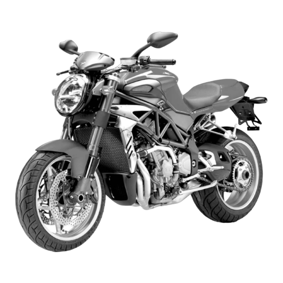
- Page 1 MV AGUSTA F4 BRUTALE S...
- Page 2 Assistance operators to use the vehicle and dispose of its replaced parts respecting the laws in force con- cerning environmental pollution and waste disposal and recycling. © 2004 This document may not, in whole or in part, be reproduced without prior consent, in writing, from MV Agusta S.p.A. Part No. 8A00A4902 - Edition No. 1 Printed in...
- Page 3 Use and maintenance manual...
- Page 4 Il presente Manuale di uso e manutenzione è disponibile nelle edizioni in lingua sotto specificate: This Manual is available in the languages listed below: Le présent livret d’utilisation et d’entretien est disponible dans les éditions rédigées dans les langues spécifiées ci-dessous: Die vorliegende Bedienungs- und Wartungsanleitung ist in folgenden Sprachen erhältlich: Las ediciones del presente manual de uso y mantenimiento están disponibles en los siguientes idiomas: Codice/Code/Code...
- Page 5 MV Agusta models, strenghtening a design phylosophy that involves continuous research, tech- nological innovation and love for detail. This way, MV Agusta gives to all the bikers who freely live their passion the chance to possess a unique object, which surely represents a strong reference worldwide.
-
Page 6: Table Of Contents
CONTENTS chap. Subject covered page chap. Subject covered page GENERAL INFORMATION 3.2. Sidestand 1.1. Purpose of the manual 3.3. Handlebar controls, left side 1.2. Symbols Handlebar controls, right side 1.3. Warranty Booklet and Service Coupons 3.5. Ignition switch and steering lock 1.4. - Page 7 CONTENTS chap. Subject covered page chap. Subject covered page Riding 6.2. Tools and accessories supplied ADJUSTMENTS 6.3. Table of lubricants and fluids 5.1. List of adjustments 6.4. Checking the engine oil level 5.2. Table of adjustments 6.4.1. Topping up the engine oil level 5.3.
- Page 8 CONTENTS chap. Subject covered page 6.12.8. Replacing the license plate light bulb 6.13. Battery 6.14. Cleaning the motorcycle 6.15. Prolonged inactivity TROUBLESHOOTING FLOW CHART 7.1. Engine problems 7.2. Electrical equipment problems TECHNICAL INFORMATION 8.1. Motorcycle overview 8.1.1. Front brake circuit 8.1.2.
- Page 9 INDEX Accessories – rear light and brake light – installation – rear turn indicators Adjustments – clutch lever Chain – front brake lever – check – front suspension – lubrication – headlight Cleaning the motorcycle – list Clutch – rear suspension –...
- Page 10 INDEX Display, multifunction Identification data – selecting functions Idle speed, check – setting functions Ignition switch and steering lock Instruments and warning lights Electrical equipment, troubleshooting Engine Levels – lubrication – brake fluid – oil level, check – clutch fluid –...
- Page 11 INDEX Topping up Rear light and brake light, – coolant bulb replacement – engine oil Rearview mirrors, adjustment Troubleshooting flow chart Refuelling – electrical equipment Replacing parts, general information – engine Running-in Turn indicators – front, bulb replacement Safety – rear, bulb replacement –...
-
Page 12: General Information
GENERAL INFORMATION 1.1. Purpose of the manual In addition to providing directions on operation and mainte- nance, this manual contains important information about gen- eral safety: READ THE MANUAL OVER CAREFULLY BEFORE FIRST USING THE MOTORCYCLE. The manual describes the model with the maximum equip- ment at print time. -
Page 13: Symbols
GENERAL INFORMATION 1.2. Symbols Sections of text that are particularly important in terms of personal safety or possible damage to the motorcycle are marked with the following symbols: Danger - Failure to observe these prescriptions, even in part, may pose a serious hazard to the driver’s and other people’s safety. -
Page 14: Warranty Booklet And Service Coupons
IMPORTANT The copy of the Warranty and Pre-Delivery Certificate to be sent to MV Agusta must be filled in by the dealer and returned to the factory within 10 days from the date of registration. Every time the vehicle is serviced by a dealer, the user must... -
Page 15: Identification Data
GENERAL INFORMATION 2) engine serial number 3) homologation data 1) vehicle identification number 1.4. Identification data 1) vehicle identification number 2) engine serial number 3) homologation data Motorcycle identification We recommend writing down the main numbers The motorcycle is identified by the vehicle identi- in the spaces provided below. - Page 16 ZCG F4 05 AA Y V 000000 Manufacturer’s Letter Code Motorcycle model Progressive vehicle number The vehicle identification number must be provided each time you need to contact the MV Agusta Technical Assistance Service, in order to guarantee the traceability of your motorcycle. - 14 -...
- Page 17 GENERAL INFORMATION Motorcycle key identification key identification number A key is supplied in duplicate for both the ignition and all the locks. Keep the duplicate in a safe place. It is essential to provide the key identification number if you place an order for a spare motorcycle key. We recommend writing down this number in the space pro- vided below: KEY No.:...
- Page 18 GENERAL INFORMATION - 16 -...
- Page 19 GENERAL INFORMATION Bodywork parts reference colours Bodywork parts are painted with the following reference colours, according to the corresponding motorcycle colour combination (see page 20): 1. - Rear side fairing, right-hand; 4. - Fuel tank: 2. - Rear side fairing, left-hand; Colour combination A: CRC B4 Red Painting 3.
- Page 20 GENERAL INFORMATION - 18 -...
- Page 21 GENERAL INFORMATION Frame parts reference colours Frame parts are painted with the following reference colours: 1. - Frame; 4. - Front wheel rim; 5. - Rear wheel rim: Colour combinations A-B-C: Brutale Metal Anthracite Grey Painting Aluminium Grey Painting (Code Palinal 211XH893) (Code Sebino 35204189) + Colour combination D: Transparent Painting...
- Page 22 GENERAL INFORMATION Identification of motorcycle colour combination The colour code must be mentioned when ordering body spares. It can be read on the lower left side of the fuel tank. In order to get to the colour code label, it is necessary to remove the fuel tank left-hand side fairing.
- Page 23 GENERAL INFORMATION After removing the fuel tank left-hand side fairing, it is colour code label possible to get to the colour code label. On this label you can read the motorcycle colour combination, which determines the painting of the bodywork parts. We recommend writing down the colour code in the space provided below: COLOUR CODE :...
-
Page 24: Safety Information
If you notice a progressive increase of the noise ery to the ultimate purchaser or while it is in use. level of your motorcycle, MV Agusta recommends 2. The use of the vehicle after such device or ele- to have your noise control system controlled and ment of design has been removed or rendered if necessary replaced. -
Page 25: Safety Rules
MV Agusta dealer to obtain the neces- Do not attach a sidecar, a trailer or any other sary explanations. - Page 26 SAFETY INFORMATION Do not ride this motorcycle if you do not pos- When refuelling, stay away from the vehicle to sess a regular driving licence. Failure to heed this avoid inhaling harmful fumes. Should the fuel warning constitutes a breach of the Highway come into contact with the skin or clothes, imme- Code, besides posing a serious hazard to the dri- diately wash with water and change the contami-...
-
Page 27: Precautions For Children
Do not use the vehicle if you detect a damage that could adversely affect safety. Have all the main parts checked by an authorized MV Agusta dealer, in order to verify the absen- ce of defects and/or damages that the owner could not be able to detect. -
Page 28: Installing Accessories
2.1.4. INSTALLING ACCESSORIES possible. The brackets and the anchor bolts must be carefully checked after the assembling, to MV Agusta provides a range of accessories spe- ensure a stable framework and an unmovable cially designed for your vehicle. It is essential that support for the accessory. -
Page 29: Vehicle Load
SAFETY INFORMATION sideways and transversely; this may also happen 2.1.5. VEHICLE LOAD when your motorcycle runs into or it is overtaken Your motorcycle is designed for use by the rider by vehicles of great dimensions. Under these con- and it can also seat a passenger. To use the vehi- ditions, the accessories adversely affect your dri- cle in complete safety and in accordance with the ving safety, especially if they are incorrectly... - Page 30 SAFETY INFORMATION WARNING • Never carry any incorrectly fastened Since the load can strongly affect hand- object on your motorcycle, because it ling, braking, performance and safety could move from its position during characteristics of your motorcycle, you riding. should always keep in mind the fol- •...
-
Page 31: Modifications
SAFETY INFORMATION 2.1.6. MODIFICATIONS 2.1.7. COMPETITIONS MV Agusta suggests neither to remove any origi- WARNING: Riding the vehicle in compe- nal device, nor to modify the motorcycle in any titions requires considerable skill and way that could change its shape or its working. -
Page 32: Recommendations For Safe Riding
SAFETY INFORMATION 2.1.8. RECOMMENDATIONS FOR SAFE RID- Being aware of one’s limits When riding, never exceed your limits nor those imposed by law. Being aware of your limits and Besides being a means of transport, your motor- acting accordingly will help you avoid accidents. cycle is a source of recreation and excitement. - Page 33 SAFETY INFORMATION Keeping even one foot or hand away from their overheating and to the abnormal wear of the clut- designed supports could cause loss of control of ch components. the vehicle and increase the risk of accidents. When rapid acceleration is required (e.g. when Always keep both hands on the handlebars and passing), select a lower gear to obtain better both feet on the footrests during riding.
- Page 34 SAFETY INFORMATION The braking action should always be applied gen- Maintain a safe distance behind vehicles in tly and gradually to both wheels. front of you and adjust your speed to the weather and traffic conditions. Remember that, as your Performing this operation and, more in general, riding the vehicle always requires the utmost care.
-
Page 35: Protective Clothing
SAFETY INFORMATION 2.1.9. PROTECTIVE CLOTHING A close fitting jacket, made of tough material and easy to fasten. Helmet wearing is compulsory under the Highway Supple, reinforced gloves providing both sen- Code. Helmet is the most important part in the sitivity and protection. biker’s protective clothing, because it protects him Strong, close-fitting trousers covering the legs from head injury in the event of an accident. -
Page 36: Suggestions Against Theft
SAFETY INFORMATION WARNING 4. Always keep up to date the registration data of Protective clothes do not afford com- your motorcycle. plete protection against the risk of per- 5. Write down your name, address and phone sonal injury in the event of an accident. number in the spaces provided down below, It is therefore essential not be deceived and always keep this use and maintenance... -
Page 37: Safety Labels - Location
4 - Rear wheel hub warning 5 - Chain adjustment NOTE The labels in the following pages do not appear in their real size. If you find difficulties in under- standing any of these labels, contact an authorized MV Agusta dealer. - 35 -... - Page 38 SAFETY INFORMATION 1. ADHESIVE LABEL – UNLEADED PETROL 2. ADHESIVE LABEL – BATTERY WARNING - 36 -...
- Page 39 SAFETY INFORMATION 3. ADHESIVE LABEL – TYRE PRESSURE 4. ADHESIVE LABEL – REAR WHEEL HUB WARNING - 37 -...
- Page 40 SAFETY INFORMATION 5. ADHESIVE LABEL – CHAIN ADJUSTMENT - 38 -...
-
Page 41: Safety - Visual And Acoustic Signals
SAFETY INFORMATION 2.3. Safety - Visual and acoustic signals Before each ride, it is essential to verify the operation of the visual and acoustic signals. Parking light, low and high beams (§ 3.3) Parking light (§ 3.3) and brake light Turn indicators (§... -
Page 42: Controls And Instruments
CONTROLS AND INSTRUMENTS 3.1. Location of controls and instruments Handlebar electrical controls, left side (§ 3.3) Instruments and warning lights (§ 3.7) Ignition switch and steering lock (§ 3.5) Left side Right side Fuel tank cap (§ 4.5) Handlebar electrical controls, right side (§ 3.4) Throttle twist grip (§... - Page 43 CONTROLS AND INSTRUMENTS Front brake lever (§5.1.) Clutch lever (§5.1.) Rearview mirrors (§5.1.) Passenger footrest Passenger Passenger handhold footrest Passenger handhold Rear brake lever (§5.1.) Rider footrest (§5.1.) Gear lever (§3.6. and §5.1.) Sidestand (§3.2.) Rider footrest (§5.1.) - 41 -...
-
Page 44: Sidestand
CONTROLS AND INSTRUMENTS 3.2. Sidestand The sidestand is equipped with a safety switch that prevents the motorcycle from moving off while the stand is down. If the rider attempts to engage the gears while the engine is running and the stand is down, the switch auto- matically turns off the engine by cut- ting the current supply. -
Page 45: Handlebar Controls, Left Side
CONTROLS AND INSTRUMENTS 3.3. Handlebar controls, left side Clutch lever Move towards/away from the handgrip to release/engage the clutch. High beam flasher button Press the button repeatedly. Low/high beam button Button not pressed in : low beam Button pressed in : high beam Horn button Press to operate the warning horn. - Page 46 CONTROLS AND INSTRUMENTS High beam flasher button It is used to attract the attention of other road users in case of danger. When the high beam is on, the function is inactive. Low/high beam button Under normal conditions, the low beam is on. The high beam can be switched on by pressing the but- ton when allowed by the traffic and road conditions.
-
Page 47: Handlebar Controls, Right Side
CONTROLS AND INSTRUMENTS 3.4. Handlebar controls, right side Front brake lever Pull to the lever to apply the front brake. Throttle twist grip Rotate counterclockwise to increase engine speed. Cold start (choke) lever Rotate clockwise when cold starting. After the engine has run for a few seconds, return the lever to its original position. - Page 48 CONTROLS AND INSTRUMENTS Engine stop switch It is used to switch off the engine in an emergency. The ignition circuit is disabled, preventing the engine from being restarted. To be able to restart the engine, return the switch to its original position. NOTE Under normal conditions, do not use this switch to shut off the engine.
- Page 49 CONTROLS AND INSTRUMENTS Throttle twist grip It controls the fuel-air mixture supplied to the engine, which regulates engine speed. To increase engine speed, rotate the hand grip from its idle position counterclockwise. When cold starting (choke on), rotating the throttle twist grip clockwise fully causes the choke lever to return to its original position.
-
Page 50: Ignition Switch And Steering Lock
CONTROLS AND INSTRUMENTS 3.5. Ignition switch and steering lock WARNING Do not attach a ring or any other object to the ignition key as they may hinder the steering action. WARNING Never attempt to change the switch functions while riding, as you may lose control of the vehicle. OFF Position Ignition switch and steering lock ON Position... - Page 51 CONTROLS AND INSTRUMENTS The ignition switch enables and disables the electrical circuit and the steering lock. The four positions of the switch are described below. OFF position ON position All electrical circuits are deactivated. The key can All electrical circuits are activated. The instru- be removed.
- Page 52 CONTROLS AND INSTRUMENTS LOCK position Turn the handlebar to the left. Press the key in gently while rotating it to the LOCK position. All electrical circuits are deactivated and the steering is locked. The key can be removed. Left side Right side - 50 -...
- Page 53 CONTROLS AND INSTRUMENTS P (PARKING) position CAUTION Do not leave the key on the P position Turn the key from the LOCK position to the P for a long time, in order to avoid position. All electrical circuits are deactivated discharging battery your...
-
Page 54: Gear Lever
CONTROLS AND INSTRUMENTS 3.6. Gear lever The N (neutral) position is indicated by the warning light on the instrument panel. To change into first gear, push the lever down. To change into second gear, lift the lever up. Lifting the lever up repeatedly engages all the other gears in succession up to the sixth speed. -
Page 55: Instruments And Warning Lights
CONTROLS AND INSTRUMENTS 3.7. Instruments and warning lights The instruments and warning lights are activated by turning the ignition switch to the ON position. After a preliminary check (approx. 7 seconds) the displayed information reflects the current general condition of the motorcycle. Warning lights (§3.7.1.) Warning light... -
Page 56: Warning Lights
CONTROLS AND INSTRUMENTS 3.7.1. Warning lights High beam warning light (blue) Battery charge indicator (red) Lights up when the alternator does not supply enough Lights up when the high beam is activated. current to charge the battery. If the indicator comes on while Low beam warning light riding, contact an authorized ser- (green) -
Page 57: Multifunction Display
CONTROLS AND INSTRUMENTS 3.7.2. Multifunction display Thermometer Speedometer Displays the coolant temperature in degrees centigrade Measures the speed of the vehicle. The speed (°C) or Fahrenheit (°F). can be displayed in kilometres per hour (km/h) The display range is 40° to 140° C (104° to 284° F): or miles per hour (mph). -
Page 58: Operation
Everything we do affects the whole planet as well as its resources. MV Agusta, in order to protect the interests of the community, awakens the Customers and the Technical Assistance opera- tors to use the vehicle and dispose of its replaced parts respecting the laws in force concerning environmental pollution and waste disposal and recycling. -
Page 59: Running-In
OPERATION Running-in CAUTION Failure to observe the indications provided 5500-6000 rpm below can reduce performance and shorten the life of the motorcycle. Running-in is generally considered to apply only to the engine. In fact, it should be regarded as an essential phase for other important parts such as the tyres, the brakes and the drive chain. - Page 60 OPERATION 500 to 1000 km (300 to 600 mi) Avoid lugging or overspeeding the engine, and vary your speed frequently. 8000-9000 rpm 1000 to 2500 km (600 to 1600 mi) Higher engine performance can be demanded, but it is advisable not to exceed the engine speed shown in the 11000 rpm figure.
-
Page 61: Starting The Engine
OPERATION 4.3. Starting the engine CHOKE lever WARNING Starting the engine in a closed place can be dangerous. Exhaust emissions contain car- bon monoxide, a colourless and odourless gas that can lead to serious harm or even death when inhaled. Only start the engine outdoor, in the open air. - Page 62 OPERATION As soon as the engine starts, release the button and, after warming up the engine for a short time, return the CHOKE lever to its original position. Hot starting Press the start button without turning the throttle twist grip. As soon as the engine starts, release the button.
-
Page 63: Selecting And Setting The Display Functions
OPERATION 4.4. Selecting and setting the display functions The display functions allow to change some of the main measuring parameters. The possible operations are listed as follows: - Selecting the functions: TOTAL Mileage Counter TRIP 1 Mileage Counter TRIP 2 Mileage Counter Clock... -
Page 64: Selecting The Display Functions
OPERATION 4.4.1. Selecting the display func- tions You can select the following functions: • TOTAL Mileage Counter • TRIP 1 Mileage Counter • TRIP 2 Mileage Counter • Clock The TOTAL, TRIP 1 and TRIP 2 functions can be displayed by pres- sing the engine start button. -
Page 65: Setting The Measurement Units
OPERATION 4.4.2. Setting the measurement units It is possible to set the measurement units of the displayed quantities. WARNING The operation must be performed while the engine is running, the gears are in neutral, the motorcycle is stationary, and with the feet on the ground. - Page 66 OPERATION Press the engine start button to toggle between Km/h and Mph. Changing the speedometer unit also changes the units for the total and trip mileage counters. Remember that: 1 mi = 1,609 Km Press the SET button to confirm the speedometer unit.
- Page 67 OPERATION Thermometer (° C - ° F) Press the engine start button to toggle between ° C and ° F. Remember that: T (°F) = 1.8 • t (°C) + 32 Press SET to confirm the temperature unit. - 65 -...
-
Page 68: Resetting The Trip Mileage Counters
OPERATION 4.4.3. Resetting the trip mileage counters The TRIP 1 and TRIP 2 counters can be reset as fol- lows: WARNING The operation must be performed while the engine is running, the gears are in neutral, the motorcycle is stationary, and with the feet on the ground. - Page 69 OPERATION Pressing the button for less than four seconds sets the mileage to zero. If, on the other hand, the button is pressed for longer than four seconds the entire resetting procedure is cancelled. Select the TRIP 2 function by pressing the engine start button.
- Page 70 OPERATION Press the engine start button for longer than four seconds; the TRIP 2 mileage will start blinking. Pressing the button for less than four seconds sets the mileage to zero. If, on the other hand, the button is pressed for longer than four seconds the entire resetting procedure is cancelled.
-
Page 71: Setting The Clock
OPERATION 4.4.4. Setting the clock It is possible to set the clock function. WARNING The operation must be performed while the engine is running, the gears are in neutral, the motorcycle is stationary, and with the feet on the ground. Do not set the display functions while riding as it may cause loss of control of the vehicle. - Page 72 OPERATION Hold down the engine start button and release it as soon as the desired figure is displayed. NOTE To quickly cycle through the selected digit, hold the start button depressed for longer than two seconds. Press SET to confirm the first hour digit and to be able to set the following digit.
-
Page 73: Refuelling
OPERATION 4.5. Refuelling WARNING Petrol and its fumes are highly toxic and flam- mable. Avoid contact and inhalation. When refuelling, switch off the engine, avoid smoking, and keep away from flames, sparks and heat sources. Perform refuelling in the open air or in a well ventilated area. CAUTION Only use unleaded fuel with a R.O.N. - Page 74 OPERATION Lift the tank cap and operate the refuelling. WARNING Overfilling the tank may cause the fuel to overflow as a result of the expansion due to the heat from the engine or to exposure to sunlight. Fuel spills can catch fire. The level of the fuel in the tank must never be higher than the base of the filler.
-
Page 75: Glove Compartment
OPERATION 4.6. Glove compartment Insert the key into the lock. Press down the pillion while turning the key clockwise. Lift the pillion. - 73 -... - Page 76 OPERATION Remove the pillion. In order to reassemble the above mentioned part, you must perform the following operations: • Rotate the key into the lock • Press down the pillion • Release the key • Press down the pillion once more, so to make sure of its firm coupling to the frame.
-
Page 77: Parking The Motorcycle
Never leave the vehicle unattended by your MV Agusta dealer before using the while the engine key is in the dashboard. motorcycle. Using your foot, lower the sidestand as far as it will go, and then slowly tip the motorcycle toward you to bring the stand supporting foot into contact with the ground’s surface. - Page 78 OPERATION Using the rear stand Insert the stand pin into the rear wheel axle hole on the left side of the motorcy- cle. Rest the stand on the ground and, pressing down on the stand, lift the vehi- cle until it reaches a stable condition. CAUTION This operation is best carried out with two people, one to...
-
Page 79: Preriding Checks
OPERATION 4.8. Preriding checks Pull lever and check that it moves smoothly and gradually. Lubricate the lever joint, if necessary. WARNING Engine start button / stop switch A motorcycle can be in good running Check operation (§3.4). order and then become unexpectedly Throttle twist grip unreliable even if unused (e.g. - Page 80 OPERATION Fuel WARNING Check level. If any of the above-mentioned parts Refuel, if necessary (§4.5). shows a failure during its operation, Check for fuel leakage. have it controlled and repaired before Engine oil using the motorcycle. Check level (§6.4). Check for leakage. Sidestand Check return to stowed position.
-
Page 81: Riding
OPERATION 4.9. Riding Riding a motorcycle requires experience and concentration. Inexperienced riders should undergo a period of training and attend an introductory course consisting of theoretical lessons as well as practical riding sessions in areas closed to traffic. The instructor’s advice will help the novice rider become familiar with the basics of riding safety. Relying on the advice of persons other than a qualified riding instructor, even if possessing specific knowledge, may prove to be useless or even dangerous, especially if the practical training takes place in an area open to traffic. -
Page 82: Adjustments
ADJUSTMENTS 5.1. List of adjustments There are many adjustments that can significantly improve the ergonomics, geometry and safety of the motorcycle. Some of these can only be performed by skilled per- sonnel at authorized service centres. WARNING To avoid losing control of the vehicle while riding, be sure to always keep both hands on the handlebars. - Page 83 ADJUSTMENTS (E) Rearview mirror adjustment (§5.5.) (F) Front suspension adjustment (§5.6) (A) Front brake lever adjustment (§5.3.) (G) Rear suspension (L) Headlight adjustment (§5.7.) adjustment (§5.8.) (D) Rear brake lever adjustment (§5.2.) (F) Front suspension adjustment (§5.6) - 81 -...
- Page 84 ADJUSTMENTS (E) Rearview mirror adjustment (§5.5.) (G) Rear suspension adjustment (§5.7.) (B) Clutch lever adjustment (§5.4.) (C) Gear lever adjustment (§5.2.) (H) Drive chain adjustment (§6.10.) - 82 -...
-
Page 85: Table Of Adjustments
Do not operate the screw fixing the rear- view mirror to the handlebar. If this L - Headlight adjustment: To adjust the range of screw needs to be tightened, contact the light beam to the geometry of the motorcycle your MV Agusta dealer. (§5.8). - 83 -... -
Page 86: Adjusting The Front Brake Lever
ADJUSTMENTS 5.3. Adjusting the front brake lever 5.4. Adjusting the clutch lever WARNING WARNING Never perform the adjustment while Never perform the adjustment while riding. riding. While pulling the lever to counter the action of the While pulling the lever to counter the action of the spring, turn the ring clockwise or counterclockwi- spring, turn the ring clockwise or counterclockwi- se to move the lever away or towards the hand-... -
Page 87: Adjusting The Rearview Mirrors
ADJUSTMENTS 5.5. Adjusting the rearview mirrors WARNING Never perform the adjustment while riding. Press the mirror at the points shown in the figure to adjust its position in the four directions. Perform the adjustment on both the rearview mirrors. It is recommended to sit on the vehicle in order to optimi- ze the rearview mirrors adjustment. -
Page 88: Adjusting The Front Suspension
ADJUSTMENTS 5.6. Adjusting the front suspension Rebound damper WARNING It is essential that the adjusters of Spring preload both fork rods are adjusted to the same position. Compression damper - 86 -... -
Page 89: Spring Preload
ADJUSTMENTS 5.6.1. Spring preload 5.6.2. Rebound damper (front suspension) The adjustment is obtained from the standard The adjustment is obtained from the standard position, which is found by fully turning the adju- position, which is found by fully turning the screw sting nut counterclockwise and then clockwise clockwise and then counterclockwise (see enclo- (see enclosed table). -
Page 90: Compression Damper (Front Suspension)
ADJUSTMENTS 5.6.3. Compression damper (front suspension) CLICK! The adjustment is obtained from the standard position, CLICK! CLICK! which is found by fully turning the screw clockwise and then counterclockwise (see enclosed table). Rotate clockwise to increase the damping action or counter- clockwise to decrease it. -
Page 91: Adjusting The Rear Suspension
ADJUSTMENTS 5.7. Adjusting the rear suspension WARNING The high temperature of the exhaust pipes can cause burns. Before adjusting the rear sus- pension, shut off the engine and wait until the exhaust pipes have thoroughly cooled. High and Low speed compression damper Rebound damper - 89 -... -
Page 92: Rebound Damper (Rear Suspension)
ADJUSTMENTS 5.7.1. Rebound damper (rear suspension) The adjustment can be performed by operating on the screw placed on the lower side of the shock absor- ber, and it is obtained from the standard position. This position is found by fully rotating the ring clockwise and then counterclokwise (see enclosed table). Rotate clockwise to increase the damping action or counterclockwise to decrease it. -
Page 93: High Speed Compression Damper (Rear Suspension)
ADJUSTMENTS 5.7.3. Low speed compression damper (rear 5.7.2. High speed compression damper (rear suspension) suspension) The adjustment can be performed by operating on The adjustment can be performed by operating on the screw placed on the upper side of the shock the ring nut placed on the upper side of the shock absorber, and it is obtained from the standard absorber, and it is obtained from the standard posi-... -
Page 94: Headlight Adjustment
ADJUSTMENTS 5.8. Headlight adjustment Place the vehicle at a distance of 10 m from a vertical wall. Make sure that the motorcycle is placed on an even horizontal surface, and that the headlight’s optical axis is perpendicular to the wall. The vehicle must be held in an upright position. - Page 95 ADJUSTMENTS The headlight adjustment can be performed by rotating the screw shown in the picture. Rotate clockwise to incline the headlight downwards, counterclockwise to incline it upwards. The possi- ble adjustment range is equal to ±4° from the standard position. - 93 -...
-
Page 96: Maintenance
MAINTENANCE 6.1. Tables of scheduled maintenance and checks The main periodic checks and maintenance operations are shown in the following tables. These operations are necessary to keep the motorcycle safe and in perfect running order. The intervals indicated in the periodic maintenance and lubri- cation tables must be intended as a general guide under nor- mal riding conditions. - Page 97 Everything we do affects the whole planet as well as its resources. MV Agusta, in order to protect the interests of the community, awakens the Customers and the Technical Assistance opera- tors to use the vehicle and dispose of its replaced parts respecting the laws in force concerning environmental pollution and waste disposal and recycling.
- Page 98 Every time vehicle is used Engine oil Renew At least once a year Replace Engine oil filter (Use only MV Agusta Every time engine oil is changed genuine spare oil filters) Check / Restore level Every time vehicle is used Coolant...
- Page 99 MAINTENANCE Tables of scheduled maintenance 1000 6000 12000 18000 24000 30000 36000 km (mi) covered (600) (3800) (7500) (11200) (14900) (18600) (22400) Pre- Service coupon delivery ESCRIPTION PERATION Check / Replace Timing movable shoe Replace Every time timing chain is replaced Timing chain stretcher Check / Replace Check / Replace...
- Page 100 MAINTENANCE Tables of scheduled maintenance 1000 6000 12000 18000 24000 30000 36000 km (mi) covered (600) (3800) (7500) (11200) (14900) (18600) (22400) Pre- Service coupon delivery ESCRIPTION PERATION Check operation Every time vehicle is used Clean lever / master cyl. Every 500 ÷...
- Page 101 MAINTENANCE Tables of scheduled maintenance 1000 6000 12000 18000 24000 30000 36000 km (mi) covered (600) (3800) (7500) (11200) (14900) (18600) (22400) Pre- Service coupon delivery ESCRIPTION PERATION Flexible controls and Check / Adjust transmissions Check Every 1000 Km (600 mi) Lubricate Every 1000 Km (600 mi) and after riding under the rain Drive chain...
- Page 102 MAINTENANCE Tables of scheduled maintenance 1000 6000 12000 18000 24000 30000 36000 km (mi) covered (600) (3800) (7500) (11200) (14900) (18600) (22400) Pre- Service coupon delivery ESCRIPTION PERATION Rear sprocket spring drive Check Steering head tube ring Check / Adjust Check / Adjust Steering bearings Lubricate...
- Page 103 MAINTENANCE Tables of scheduled maintenance 1000 6000 12000 18000 24000 30000 36000 km (mi) covered (600) (3800) (7500) (11200) (14900) (18600) (22400) Pre- Service coupon delivery ESCRIPTION PERATION Check operation Every time vehicle is used Sidestand Check operation Check operation Every time vehicle is used Clean contact area Every 500 ÷...
- Page 104 MAINTENANCE Tables of scheduled maintenance 1000 6000 12000 18000 24000 30000 36000 km (mi) covered (600) (3800) (7500) (11200) (14900) (18600) (22400) Pre- Service coupon delivery ESCRIPTION PERATION Battery connections Check and clean Electrical equipment Check operation Check operation Every time vehicle is used Instrument panel Check operation Check operation...
- Page 105 Information on operations that can be carried out by the user. must only Information on operations that be performed by your authorized MV Agusta dealer. The “ ” symbol points out the requirement to use a tool or a special equipment in order to correctly perform the described operation. §...
-
Page 106: Tools And Accessories Supplied
MAINTENANCE 6.2. Tools and accessories supplied A bag in the glove compartment contains the following tools: 1 hexagonal bar (10 mm hexagon); 6 Allen keys (2,5 - 3 - 4 - 5 - 6 - 8 mm hexagons); 1 spanner for rear wheel eccentric with extension; 2 fuses (7.5 A and 15 A). -
Page 107: Table Of Lubricants And Fluids
MOTUL CHAIN LUBE PLUS – : MV Agusta suggests to refer directly to its authorized dealers in order to purchase the recommended product. The AGIP Racing 4T 10W/60 engine oil has been expressly produced for the F4 motorcycle engine. If the above described lubricant is not available, MV Agusta... -
Page 108: Checking The Engine Oil Level
MAINTENANCE 6.4. Checking the engine oil level Check the oil level while the engine is not running, and has been allowed to cool down for at least ten minutes after a ride. The check must be performed after placing the motor- cycle in an upright position on a horizontal surface. -
Page 109: Topping Up The Engine Oil Level
MAINTENANCE 6.4.1. Topping up the engine oil level To top up the engine oil level, remove the oil filler plug and pour an appropriate amount of engine oil of the recommended type. Never exceed the MAX level mark. At the end of the operation, place back the oil filler plug. - Page 110 MAINTENANCE WARNING New or exhaust engine oil can be dan- • Keep new or exhaust engine oil out of gerous. Engine oil is highly toxic for reach of children and domestic animals. people and domestic animals. Avoid • While topping up the engine oil, wear ingestion and contact.
-
Page 111: Checking The Coolant Level
MAINTENANCE 6.5. Checking the coolant level Check the coolant level while the engine is off and cold. The check must be performed after placing the motorcy- cle in an upright position on a horizontal surface. Ensure that the coolant level is between the MIN mark and the lower side of the frame tube as shown in the figure. -
Page 112: Topping Up The Coolant Level
MAINTENANCE 6.5.1. Topping up the coolant level To gain access to the coolant filler cap, extract the cover after by removing its fixing screws. Remove the coolant filler cap and top up with the recommended coo- lant (see §6.3). Coolant filler cap After topping up, carefully replace the previously removed parts. - Page 113 MAINTENANCE WARNING: Perform the topping up of WARNING the coolant when the engine is off and Under certain conditions, ethylene gly- cold. Never attempt to remove the coo- col contained in the coolant can become lant filler cap when the engine is hot, in flammable.
-
Page 114: Checking The Wear Of The Brake Pads
MAINTENANCE Front brake caliper Rear brake caliper Disc 6.6. Checking the wear of the brake pads Pads The brake pads have grooves that provide an indication of the wear condition. Periodically check the width of the grooves, making sure it never falls below the wear limit (1 mm). -
Page 115: Checking The Brake Fluid Level
MAINTENANCE Rear brake fluid reservoir Front brake fluid reservoir 6.7. Checking the brake fluid level WARNING The level of the brake fluid decreases as the Lack of maintenance of the braking sys- brake pads wear down. Ensure that the fluid level tem can increase the risk of accidents. - Page 116 If the brake fluid comes in have a braking system bleeding perfor- touch with your skin or eyes, immedia- med by an authorized MV Agusta dealer tely wash with water. before riding your motorcycle again. - 114 -...
-
Page 117: Checking The Clutch Fluid Level
MAINTENANCE 6.8. Checking the clutch fluid level The fluid level must be between the MAX and MIN marks. If the level falls below the MIN mark, contact an autho- rized service centre and have the clutch control system repaired. WARNING Never use your motorcycle if the fluid level is below the MIN mark. -
Page 118: Checking And Replacing The Tyres
MAINTENANCE 6.9. Checking and replacing the tyres WARNING Before using the motorcycle, always check the pressure and wear of the tyres. Checking the inflating pressure of the tyres is an essential requirement to ensu- re driving safety. Insufficiently inflated tyres can reduce the handling of the motorcycle and wear themselves out very quickly. - Page 119 Moreover, it is extremely important to check the excessively worn out, have it replaced wear of the tyres before riding. In fact, a worn out by your MV Agusta dealer. Besides tyre can be punctured more easily than a new being illegal, riding a motorcycle with...
- Page 120 MAINTENANCE MV Agusta dealer and have the tyre have been designed for use with tube- replaced. With a provisionally repaired less tyres only. Do not assemble an air tyre, never exceed 60 km/h. Tyre repair- tube tyre on rims designed for tubeless ing must never be performed if the tyre tyres.
- Page 121 Wheel pin with M50x1.5 mm left-hand pitch tread ped workshop. Always have the tyres replaced by an authorized 55 mm polygonal socket wrench MV Agusta dealer. Torque wrench - 119 -...
- Page 122 WARNING approved counterweights on the wheel If you find that the wheel rim is dama- rim. MV Agusta recommends not to use ged, have it replaced by an authorized balancing or balancing/sealing fluids. MV Agusta dealer. Never attempt to...
-
Page 123: Checking And Lubricating The Drive Chain
If the chain is only partially loosened, it means that some chain links are flattened or seized. If the distance is greather than 11 mm, have the chain adjusted by your local MV Agusta dealer. - 121 -... - Page 124 WARNING rear wheel hub screws, contact an If any chain link is flattened or seized, you authorized MV Agusta dealer. In order to must correctly lubricate the chain accor- tighten the screws, apply a tightening ding to the procedures shown in the fol- torque equal to the value shown in the lowing paragraph.
- Page 125 MAINTENANCE Lubrication To ensure proper operation, the drive chain needs to be properly lubricated. Preliminary cleaning - Before lubrication, the dirt accumulated on the chain must be dissolved using kerosene. The dirt must then be removed with a clean rag and/or an air jet. CAUTION The chain is of the O-ring type.
- Page 126 MAINTENANCE Lubrication - Apply a slight and uniform film of lubricant over the whole length of the drive chain, taking care not to smear the surrounding parts, and in particular the tyres. CAUTION Only use the lubricant specified in the paragraph 6.3.
-
Page 127: Checking The Idle Speed
MAINTENANCE 6.11. Checking the idle speed Check the idle speed when the engine has reached the operating temperature. Ensure that the choke control has not been activated. The idle speed should range from 1,050 to 1,250 rpm. If a tune-up is necessary, contact an authorized service centre. -
Page 128: Replacing Parts - General Information
MAINTENANCE 6.12. Replacing parts - General information 6.13.1. Replacing the fuses The replacement of the fuses (except for the bat- The recharge fuse is located under the driver’s tery recharge fuse) and the light bulbs can be car- saddle, in the position shown in the figure. ried out by the owner according to the indications provided below. - Page 129 MAINTENANCE The service fuses are located on the right side. To expose them, remove the right hand fuel tank side fairing. Remove the cover. CAUTION Turn the ignition key on the “OFF” posi- tion before checking or replacing the fuses, in order to avoid a short circuit with subsequent damage to other elec- tric parts of the motorcycle.
- Page 130 MAINTENANCE To identify the position and function of the fuses, refer to the information shown on the adhe- sive label and in the enclosed electrical diagram. The reference letters in the figure correspond to those shown in the diagram. Replace the blown fuse and refit the cover. Remember that the tool bag contains two spare fuses.
-
Page 131: Replacing The Low Beam Bulb
MAINTENANCE 6.12.2. Replacing the low beam bulb Remove the headlight lateral fixing screws. Pay attention in silpping off the adjuster from its seat when the headlight is being removed from its support. Before removing the headlight from its support, deta- ch the connector on the rear side of the headlight. - Page 132 MAINTENANCE Remove the headlight rear screw. Remove the front part of the headlight from its sup- porting shell. Detach the low beam bulb connector. Remove the protective cap. Release the retaining spring. Extract the burnt-out low beam bulb. CAUTION: Do not touch the bulb glass with bare hands.
-
Page 133: Replacing The High Beam Bulb
MAINTENANCE 6.12.3. Replacing the high beam bulb Remove the headlight from its support as described in paragraph 6.12.2. Extract the high beam bulb by rotating it counter- clockwise. Detach the connector from the burnt-out bulb. CAUTION: Do not touch the bulb glass with bare hands. -
Page 134: Replacing The Front Parking Light Bulb
MAINTENANCE 6.12.4.Replacing the front parking light bulb Remove the headlight from its support as described in paragraph 6.12.2. Extract the front parking light bulb holder by rotating it counterclockwise. Pull out the burnt-out bulb. CAUTION: Do not touch the bulb glass with bare hands. -
Page 135: Replacing The Front Turn Indicator Bulbs
MAINTENANCE 6.12.5. Replacing the front turn indicator bulbs Remove the fixing screw. Remove the lens. To remove the burnt-out bulb, press it and rotate it counterclockwise. To fit the new bulb, press it and rotate it clockwise. Replace the lens and insert the fixing screw. - 133 -... -
Page 136: Replacing The Rear Turn Indicator Bulbs
MAINTENANCE 6.12.6. Replacing the rear turn indicator bulbs Remove the fixing screw. Remove the lens. To remove the burnt-out bulb, press it and rotate it counterclockwise. To fit the new bulb, press it and rotate it clockwise. Replace the lens and insert the fixing screw. - 134 -... -
Page 137: Replacing The Rear Light And Brake Light Bulb
MAINTENANCE 6.12.7. Replacing the rear light and brake light bulb Lift the pillion (§4.6.). Remove the bulb holder by turning it counterclockwi- To remove the bulb, press it and rotate it counter- clockwise. To fit the new bulb, press it and rotate it clockwise. Replace the bulb holder and lock it in place by rota- ting it clockwise. -
Page 138: Replacing The License Plate Light Bulb
MAINTENANCE 6.12.8. Replacing the license plate light bulb Remove the cable rail fixing screws. Pull down the cable rail and detach it from the upper surface, operating as described in the picture. - 136 -... - Page 139 MAINTENANCE Pull out the license plate light bulb holder. Extraxt the burnt-out bulb. Fit the new bulb. Replace the bulb holder. Push back the cable rail in touch with the upper sur- face. Replace the cable rail fixing screws. - 137 -...
-
Page 140: Battery
15 minutes, and trical problems or a difficult starting), have it immediately call a doctor. recharged by an authorized MV Agusta dealer as • CONTACT WITH SKIN: Wash away soon as possible. Remember that the battery runs with a great amount of water. - Page 141 When removing the battery, disconnect battery, it is essential to have it recharged by your the negative terminal FIRST and then MV Agusta dealer every 4-5 months. the positive terminal. When reinstalling the battery, use the reverse procedure. - 139 -...
-
Page 142: Cleaning The Motorcycle
MAINTENANCE 6.14. Cleaning the motorcycle Periodic careful cleaning is a key fac- tor in preserving the value of the motorcycle, protecting its surface fin- ish and checking for damages, wear and leakage of corrosive fluids. CAUTION Before washing the vehicle, stop up the exhaust pipes and protect the electrical parts. - Page 143 MAINTENANCE Wash the motorcycle with water, a mild detergent WARNING and a sponge. Wipe the vehicle with a soft cloth. Avoid smearing brakes or tyres with oil Use an air jet to dry difficult-to-reach areas. or wax. If necessary, clean the brake discs with a brake disc detergent or with CAUTION acetone, and wash the tyres with warm...
- Page 144 MAINTENANCE Clutch master cylinder piston Front brake master cylinder piston Safety switch Sidestand Front brake lever Clutch lever CAUTION Make sure to always keep clean the contact areas between the following components, as shown in the above figures: • Side stand and safety switch •...
-
Page 145: Prolonged Inactivity
MAINTENANCE 6.15. Prolonged inactivity If the motorcycle is to remain unused for a long time, it is advisable to carry out the following operations: Empty the fuel tank. Remove the battery and store it in a suitable place. Remove the spark plug caps and the spark plugs. Pour a teaspoonful of engine oil in every spark plug hole, then place back the spark plugs and the corresponding caps. -
Page 146: Troubleshooting Flow Chart
TROUBLESHOOTING FLOW CHART 7.1. Engine problems: ENGINE DOES NOT START Start “enable” Press start “enable” Problem solved switch Engine starts switch depressed Disengage gears or lift Gears engaged stand and pull clutch Problem solved and side stand Engine starts lever down Starting procedure Correctly perform starting... - Page 147 TROUBLESHOOTING FLOW CHART continued from previous page Refuel (§4.5.) Problem solved Fuel tank empty Engine starts Replace fuse(s) Problem solved Fuses are OK Engine starts (§6.12.1.) Contact an authorized service centre - 145 -...
- Page 148 TROUBLESHOOTING FLOW CHART ENGINE IS DIFFICULT TO START Starting procedure Correctly perform starting Problem solved correctly per- Engine starts procedure (§4.3.) formed Contact an authorized service centre - 146 -...
- Page 149 TROUBLESHOOTING FLOW CHART ENGINE OVERHEATS Engine cools Coolant level is Restore level Problem solved down to operat- correct (§6.5.1.) ing temperature (§6.5.) Engine cools Replace fuse Cooling fan fuse Problem solved down to operat- (§6.12.1.) is OK ing temperature Contact an authorized service centre - 147 -...
- Page 150 TROUBLESHOOTING FLOW CHART OIL PRESSURE IS TOO LOW Restore oil level Oil pressure is Problem solved Oil level is correct (§6.4.1.) optimal (§6.4.) Contact an authorized service centre - 148 -...
-
Page 151: Electrical Equipment Problems
TROUBLESHOOTING FLOW CHART 7.2. Electrical equipment problems: LIGHTS DO NOT WORK Replace fuse(s) Problem solved Fuses are OK Lights work (§6.12.1.) Replace bulb(s) Problem solved Bulbs are OK Lights work (§6.12.) Contact an authorized service centre - 149 -... - Page 152 TROUBLESHOOTING FLOW CHART HORN DOES NOT WORK Problem solved Replace fuse (§6.12.1.) Fuse is OK Horn works Contact an authorized service centre SPEEDOMETER DOES NOT WORK Speedometer Problem solved Replace fuse (§6.12.1.) Fuse is OK works Contact an authorized service centre - 150 -...
- Page 153 TROUBLESHOOTING FLOW CHART RESERVE FUEL WARNING LIGHT DOES NOT WORK Reserve fuel Problem solved Replace fuse (§6.12.1.) warning light Fuse is OK works Contact an authorized service centre ALTERNATOR DOES NOT CHARGE BATTERY Contact an authorized service centre - 151 -...
-
Page 154: Technical Information
TECHNICAL INFORMATION 8.1. Motorcycle overview (O) Instrument panel (P) Power Unit (B) Ignition - Power supply (R) Air box (Q) Battery (G) Rear frame (S) Exhaust system (H) Front suspension (F) Frame (N) Rear brake (M) Front brake (E) Cooling system (A) Engine (C) Gearbox (L) Rear suspension... - Page 155 TECHNICAL INFORMATION A - Engine: four-stroke, inline four-cylinder. L - Rear suspension: progressive, with single- Double-overhead camshaft valve train with sided swingarm and single shock absorber radial valves. Wet sump lubrication. with external adjusting system. B - Ignition - Power supply: integrated ignition- M - Front brake: dual semi-floating disc with six- injection system.
-
Page 156: Front Brake Circuit
TECHNICAL INFORMATION 8.1.1 Front brake circuit 1 Brake master cylinder 2 Brake lever 3 Brake line 4 Brake caliper 5 Brake discs - 154 -... -
Page 157: Rear Brake Circuit
TECHNICAL INFORMATION 8.1.2. Rear brake circuit 1 Brake lever 2 Brake master cylinder 3 Brake line 4 Brake fluid reservoir 5 Brake caliper 6 Brake disc - 155 -... -
Page 158: Clutch Circuit
TECHNICAL INFORMATION 8.1.3. Clutch circuit 1 Clutch lever 2 Clutch master cylinder 3 Clutch line 4 Clutch cylinder assembly - 156 -... -
Page 159: Engine Lubrication
TECHNICAL INFORMATION 8.1.4. Engine lubrication 1 Oil sump 2 Oil filter 3 Cylinder head oil feed pipe - 157 -... -
Page 160: Coolant Circuit
TECHNICAL INFORMATION 8.1.5. Coolant circuit 1 Expansion tank 2 Upper radiator 3 Lower radiator 4 Coolant pump - 158 -... -
Page 161: Fuel System
TECHNICAL INFORMATION 8.1.6. Fuel system 1 Throttle bodies 2 Fuel pump 3 Fuel line - 159 -... -
Page 162: Specifications
TECHNICAL INFORMATION 2020 1410 8.2. Specifications Description BRUTALE S SPECIFICATIONS Wheelbase (mm) (*) 1410 Overall length (mm) (*) 2020 Max. width (mm) Seat height (mm) (*) Min. ground clearance (mm) (*) Trail (mm) (*) 101,5 * : The indicated values must not be intended as binding informations. They can change according to the vehicle setup. - 160 -... - Page 163 TECHNICAL INFORMATION Specifications Description BRUTALE S Dry weight (Kg) Fuel tank capacity (lt) (*) Reserve fuel (lt) (*) Oil in crankcase (Kg) ENGINE Type Four-cylinder, four-stroke, 16 valves Bore (mm) 73,8 Stroke (mm) 43,8 Total displacement (cm 749,4 Compression ratio 12 : 1 Starting Electric starter...
- Page 164 TECHNICAL INFORMATION Specifications Description BRUTALE S LUBRICATION Type Wet sump IGNITION - POWER SUPPLY Type “Weber-Marelli” 1.6 M integrated ignition-injection system Inductive discharge electronic ignition, “Multipoint” electronic injection Spark plugs NGK CR9 EB Champion G59c Spark gap (mm) 0.7 ÷ 0.8 0.6 ÷...
- Page 165 TECHNICAL INFORMATION Specifications Description BRUTALE S Gear ratio (overall ratios) First gear 2.92 (14.71) Second gear 2.21 (11.14) Third gear 1.78 (8.97) Fourth gear 1.50 (7.56) Fifth gear 1.32 (6.65) Sixth gear 1.21 (6.10) FRAME Type CrMo steel tubular trellis (TIG welded) Swingarm pivot plates Aluminium alloy FRONT SUSPENSION...
- Page 166 TECHNICAL INFORMATION Specifications Description BRUTALE S FRONT BRAKE Type Dual floating disc with steel braking band Disc diameter (mm) Disc flange Steel Calipers, piston diameters (mm) 6-piston Ø 22.65; Ø 25.4; Ø 30.23 REAR BRAKE Type Single steel disc Disc diameter (mm) Caliper, piston diameter (mm) 4-piston, Ø...
- Page 167 TECHNICAL INFORMATION Specifications Description BRUTALE S Brand and type MICHELIN Pilot Power DUNLOP - Sport Max D 208 Race Replica Inflating pressure (*): Front 2.3 bar (33 psi) Rear 2.3 bar (33 psi) ELECTRICAL EQUIPMENT Equipment voltage Low beam 12V 55W High beam 12V 60W Front parking light...
- Page 168 TECHNICAL INFORMATION Specifications Description BRUTALE S Fuel tank side panels Thermoplastic material Tail piece side panels Thermoplastic material Tail piece Thermoplastic material Dashboard cover Thermoplastic material Ignition switch cover Thermoplastic material Front mudguard Thermoplastic material Chain guards Thermoplastic material Oil cooler guard Thermoplastic material License-plate holder Thermoplastic material...
-
Page 169: Accessories
Agusta Corse have undergone severe tests and rigorous checks, in order to offer to the Customers the same official warranty as all MV Agusta products. In order to request these components or consult the MV Agusta Corse Catalogue, we suggest to refer to: MV Agusta Corse S.r.l. - Sales and Technical Assistance Service Via Ovella 41 - 47893 Borgo Maggiore - Republic of San Marino (R.S.M.) -
Page 170: Clothing
8.4. Clothing MV AGUSTA Corse has designed a wide range of wear products and accessories providing high aesthe- tical and qualitative standards, helping to strenghten and consolidate the prestige of the MV Agusta tra- demark and, at the same time, making an exclusive experience out of riding an already unique vehicle. - Page 171 NOTES ................
- Page 172 NOTES ................
- Page 173 NOTES ................
- Page 174 NOTES ................
- Page 175 ELECTRICAL DIAGRAM Part No. 8A00A1805 Review 2 G / R Gy/R L O C K PA R K O F F 5-21W 17 18 19 20 21 PASSING HORN TURN P O S . Parts list Parts list Parts list Wires colors list Fuses list Letter(s)
- Page 176 BATTERY CABLES ASSEMBLY INSTRUCTION Part No. 8A00A4541 Review 1 Phase Phase 2 Phase 3 Phase Initial battery charging Assembling the battery Remove the pillion as shown in the Rotate the driver’s saddle catch as figure. shown in the figure. Perform the initial charge of the bat- Insert the motorcycle key in the rear tery according to the instruction lock.
- Page 178 MV Agusta. - To use the vehicle with passenger, we suggest to increa- se the rear suspension spring preload of 2 turns. This operation must be performed only by a MV Agusta authorized dealer. - Pour utiliser le véhicule avec le passager, nous suggérons d'augmenter la précharge de ressort de la suspension arrière de 2 tours.