Advertisement
Service Literature
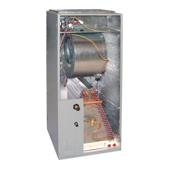
The CB26UH, and CBX26UH are high efficiency blower coils.
Several models are available in sizes ranging from 1-1/2
through 5 tons (5.3 through 17.6 kW). The CBX26UH is de-
signed for R−410A refrigerant and the CB26UH is designed for
R−22 refrigerant. The units are up flow / horizontal that can be
field converted to down flow applications. The units come with
a factory installed check and expansion valve for cooling or
heat pump applications.
CB26UH and CBX26UH series units are designed to be
matched with the 13SEER air conditioner and heat pump line,
but can be matched with other air conditioners or heat pumps
as noted in the rating information. See Engineering Handbook.
Electric heat, in several kW sizes, can be field installed in the
CB26UH and CBX26UH cabinets.
Information contained in this manual is intended for use by ex-
perienced HVAC service technicians only. All specifications are
subject to change. Procedures outlined in this manual are pre-
sented as a recommendation only and do not supersede or re-
place local or state codes.
IMPORTANT
Improper installation, adjustment, alteration, service
or maintenance can cause property damage, person-
al injury or loss of life. Installation and service must
be performed by a qualified installer or service
agency.
WARNING
Electric shock hazard. Can cause injury
or death. Before attempting to perform
any service or maintenance, turn the
electrical power to unit OFF at discon-
nect switch(es). Unit may have multiple
power supplies.
Corp. 0527−L10
CB26UH &CBX26UH Series
VI Typical Operating Characteristics
Page 1
CB26UH
CBX26UH
Table of Contents
. . . . . .
. . . . . . . . . . . . . . . . . . . . . .
. . . . . . . . . . . . . . . . . . . . . .
. . . . . . . . . . . . . . . .
. . . . . . . . . . .
. . . . . . .
. . . . . . . . . . . . . . . . . . . . . . . .
. . . . . . . . . . . . . . . . . . .
. . . . . . . . . . . . . . .
© 2005 Lennox Industries Inc.
NO TAG
Page 3
Page 4
Page 5
Page 6
Page 10
Page 13
.
Page 14
Page 14
Page 15
Litho U.S.A.
Advertisement
Table of Contents

Related Manuals for Lennox CB26UH


Summary of Contents for Lennox CB26UH
-
Page 1: Table Of Contents
Several models are available in sizes ranging from 1-1/2 through 5 tons (5.3 through 17.6 kW). The CBX26UH is de- signed for R−410A refrigerant and the CB26UH is designed for R−22 refrigerant. The units are up flow / horizontal that can be field converted to down flow applications. -
Page 2: Specifications
SPECIFICATIONS Model Number (R−22) CB26UH−018 CB26UH−024 CB26UH−030 CB26UH−036 General Data Model Number (R−410A) CBX26UH−018 CBX26UH−024 CBX26UH−030 CBX26UH−036 Nominal tonnage Connections Suction/Vapor line (o.d.) − in. (mm) sweat 3/4 (19) 3/4 (19) 7/8 (22.2) 7/8 (22.2) Liquid line (o.d.) − in. (mm) sweat 3/8 (9.5) -
Page 3: Blower Data
BLOWER DATA CB(X)26UH−018 BLOWER PERFORMANCE CB(X)26UH−024 BLOWER PERFORMANCE Air Volume at Air Volume at External Static External Static Specific Blower Taps Specific Blower Taps Pressure Pressure Pressure Pressure High High in. w.g. in. w.g. 1020 1040 1000 NOTE − All air data measured external to unit with dry coil and 1 inch non−pleated air NOTE −... -
Page 4: I Application
ELECTROSTATIC DISCHARGE (ESD) Precautions and Procedures All major blower coil components must be matched ac- cording to Lennox recommendations for the unit to be CAUTION covered under warranty. Refer to the Engineering Handbook for approved system matchups. A misapplied system will Electrostatic discharge can affect electronic components. -
Page 5: Unit Components
2−Blower Relay nameplate. All CB26UH and CBX26UH units use a DPST relay to en- ergize the blower motor. The relay coil is energized by C−Coil blower demand from indoor thermostat. When the coil is CB26UH and CBX26UH units have dual slab coils ar- energized, a set of N.O. -
Page 6: Optional Electric Heat
III−OPTIONAL ECB26 ELECTRIC HEAT TABLE 1 ECB29 CIRCUIT BREAKERS A−Matchups and Ratings UNIT Tables 2 through 4 show all approved CB26UH and AMPS AMPS AMPS CBX26UH to ECB26 matchups and electrical ratings. ECB26-5CB-1 (P) 30 AMP −−− −−− B−Electric Heat Components... - Page 7 TABLE 2 SINGLE PHASE ELECTRIC HEAT CB(X)26UH−018 / CB(X)26UH−024 Blower Minimum Maximum Motor Circuit Overcurrent Description Full Load Ampacity Protection Input Amps Volt Btuh Circuit 1 Circuit 2 Circuit 1 Circuit 2 12,800 19.5 − − − − − − 5 kW ECB26−5 (99M64) Terminal Block ECB26 5CB (99M65) Ci...
- Page 8 TABLE 3 SINGLE PHASE ELECTRIC HEAT CB(X)26UH−036 Blower Minimum Maximum Motor Circuit Overcurrent Description Full Load Ampacity Protection Input Amps Volt Btuh Circuit 1 Circuit 2 Circuit 1 Circuit 2 12,800 19.8 − − − − − − 5 kW ECB26−5 (99M64) Terminal Block ECB26−5CB (99M65) Circuit Breaker C 26 C (99 6 ) C...
- Page 9 TABLE 4 SINGLE PHASE ELECTRIC HEAT CB(X)26UH−048 Blower Minimum Maximum Motor Circuit Overcurrent Description Full Load Ampacity Protection Input Amps Volt Btuh Circuit 1 Circuit 2 Circuit 1 Circuit 2 12,800 20.7 − − − − − − 5 kW ECB26−5 (99M64) Terminal Block ECB26−5CB (99M65) Circuit Breaker C 26 C (99 6 ) C...
-
Page 10: Configuration Modification
4. Install units that have no return air plenum on a stand that is at least 14" from the floor. This will allow proper CB26UH and CBX26UHunits are factory−assembled and air return. configured for installation in upflow or horizontal left−hand air discharge applications. - Page 11 Suspending Horizontal Unit Field Modification for Right−Hand Discharge REMOVE ANGLE IRON OR Electrical Inlet Clear- DRAIN PAN SHEET METAL ance 4 in. (102 mm) FROM HERE THEN... 1/2 in. Screws max. REINSTALL PAN HERE REMOVE 2 SCREWS AND BP BRACKET FROM HERE THEN...
- Page 12 Install Condensate Drain 4. Install a 3" trap in both the primary and secondary drain lines as close to the unit as practical (see figure 13). The air handler is provided with ¾" NPT condensate drain connections. Make sure the top of the trap is below the connection to the drain pan to allow complete drainage of the pan.
-
Page 13: Start Up
V−START-UP − OPERATION setting far enough below room temperature to bring on the compressor. Compressor will start and cycle on de- A−Preliminary and Seasonal Checks mand from the thermostat. After a 30 second time delay 1− Make sure the unit is installed in accordance with the (approximate) the indoor blower will energize. -
Page 14: Maintenance
VI−TYPICAL OPERATING CHARACTERISTICS 1. Disconnect all power supplies. 2. Remove the air handler access panel. A−Blower Operation and Adjustment 3. Locate pin number 2 on the blower relay. Two black NOTE− The following is a generalized procedure and wires are connected to this terminal pin. One connects does not apply to all thermostat controls. -
Page 15: Wiring Diagrams
VIII−WIRING DIAGRAMS AND SEQUENCE OF OPERATIONS SEQUENCER 2 ELECTRIC HEAT − 2ND STAGE 18 BK CIRCUIT BREAKER 2 (OPT) 12 BK LIMIT SWITCH 3 12 BK 12 BK 12 BK LIMIT SWITCH 4 12 Y 12 Y 208/240 VOLTAGE SEQUENCER 1 CIRCUIT BREAKER 1 (OPT) ELECTRIC HEAT −...