Epson TM-H6000IV Technical Reference Manual
Pos printer
Hide thumbs
Also See for TM-H6000IV:
- User manual (159 pages) ,
- Product information manual (6 pages) ,
- Development manual (32 pages)
Table of Contents
Advertisement
Quick Links
Technical Reference Guide
Product Overview
Describes features and general specifications for the product.
Setup
Describes setup and installation of the product and peripherals.
Application Development Information
Describes how to control the printer and necessary information
when you develop applications.
Handling
Describes how to handle the product.
Replacement of the TM-H6000III
Describes precautions for replacement.
Appendix
Describes interfaces, connectors, and character code tables.
M00034100
Rev. A
Advertisement
Table of Contents

Related Manuals for Epson TM-H6000IV


Summary of Contents for Epson TM-H6000IV
- Page 1 Technical Reference Guide Product Overview Describes features and general specifications for the product. Setup Describes setup and installation of the product and peripherals. Application Development Information Describes how to control the printer and necessary information when you develop applications. Handling Describes how to handle the product.
- Page 2 • Neither is any liability assumed for damages resulting from the use of the information contained herein. • Neither Seiko Epson Corporation nor its affiliates shall be liable to the purchaser of this product or third parties for damages, losses, costs, or expenses incurred by the purchaser or third parties as a result of: accident, misuse, or abuse of this product or unauthorized modifications, repairs, or alterations to this product, or (excluding the U.S.) failure to strictly comply with Seiko Epson Corporation’s operating...
-
Page 3: For Safety
For Safety Key to Symbols The symbols in this manual are identified by their level of importance, as defined below. Read the following carefully before handling the product. You must follow warnings carefully to avoid serious bodily injury. WARNING Provides information that must be observed to prevent damage to the equipment or loss of data. -
Page 4: Warnings
• Shut down your equipment immediately if it produces smoke, a strange odor, or unusual noise. Continued use may lead to fire. Immediately unplug the equipment and contact your dealer or a Seiko Epson service center for advice. • Never attempt to repair this product yourself. Improper repair work can be dangerous. -
Page 5: Cautions
Cautions • Do not connect cables in ways other than those mentioned in this manual. Different connections may cause equipment damage or fire. • Be sure to set this equipment on a firm, stable, horizontal surface. CAUTION The product may break or cause injury if it falls. •... -
Page 6: About This Manual
About this Manual Aim of the Manual This manual was created to provide information on the development, design, and installation of POS systems and the development and design of printer applications for developers. Manual Content The manual is made up of the following sections: Chapter 1 Product Overview Chapter 2... -
Page 7: Table Of Contents
Contents ■ For Safety..........................3 Key to Symbols ............................3 Warnings ..............................4 Cautions..............................5 ■ Restriction of Use ........................5 ■ About this Manual ........................6 Aim of the Manual..........................6 Manual Content ............................ 6 Product Overview ................11 ■ Features ..........................11 ■ Product Configurations ......................13 Interfaces .............................. - Page 8 Reliability ...............................37 Environmental Conditions ........................38 External Dimensions and Mass......................39 ■ Option Specifications ......................40 Power Supply Unit (PS-180) ........................40 Setup .....................41 ■ Flow of Setup........................41 ■ Installing the Printer......................42 Important Notes ...........................42 ■ Adjusting the Paper Roll Near-End (NE) Sensor............... 43 ■...
- Page 9 ■ Software and Manuals .......................83 How to Get Drivers, Manuals, and the Utility ..................83 Printer Drivers............................83 Utilities..............................85 ■ Setting/Checking Modes....................86 Self-test Mode ............................86 Hexadecimal Dumping Mode ......................89 NV Graphics Print Mode ........................90 Receipt Enhancement Information Print Mode................92 Memory Switch Setting Mode......................
- Page 10 Two-Color Printing..........................111 Ink Ribbon Cartridge..........................111 Overall Dimensions ..........................112 ■ Additional Functions and Functional Improvements............ 113 Print Speed ............................113 Receipt Print Density ..........................113 Slip Paper.............................114 Bar codes ............................114 Tone..............................114 Interface ..............................114 Connection of Customer Display .....................115 Customized Value ..........................115 R/E Information Printing Mode ......................115 Memory Switch Setting Mode ......................116 Maintenance Counter........................116 Power Supply Unit Capacity ......................116...
-
Page 11: Product Overview
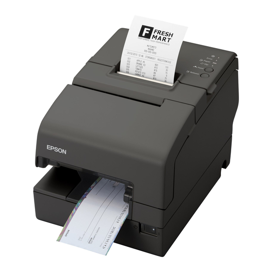
Chapter 1 Product Overview Product Overview This chapter describes features and specifications of the product. Features The TM-H6000IV is a high-end POS printer that can print on both slip paper (checks) and roll paper (receipts). The features are as follows: Slip printing •... - Page 12 • A built-in USB interface is also available for serial/parallel interface models. Environment ENERGY STAR qualified. (Some configurations may be exempted, depending on their components.) Others • Small footprint and simple design. • Direct connection of EPSON customer display series (DM-D) is possible.
-
Page 13: Product Configurations
Chapter 1 Product Overview Product Configurations There are two models of the TM-H6000IV: a standard model that can perform slip printing and receipt printing and a validation model that can also perform validation printing. An optional MICR reader that can read magnetic ink characters is available for both of the models. -
Page 14: Accessories
• AC cable (Model: AC-170) • Interface boards (UB series) • EPSON customer display series (DM-D) • Paper guide for 58 mm width paper (Model: PG-58II) For Engergy Star-compatible models, use only the AC adapter that came with the printer. -
Page 15: Part Names And Functions
Chapter 1 Product Overview Part Names and Functions Roll paper cover Control panel Receipt unit Manual cutter Front cover Power switch Power Switch Turns the printer on or off. The marks on the switch: ( : OFF/ : ON) Before turning the printer off, it is recommended that you send a power-off command to the printer. -
Page 16: Control Panel
Control Panel (Power) LED Error LED Paper LED Slip LED Feed button Release button Power LED (Green) • Lights when the power supply is on. • Goes out when the power supply is turned off. Error LED (Orange) Lights or flashes when the printer is offline. •... -
Page 17: Offline
Chapter 1 Product Overview Feed button Pressing this button once feeds paper by one line. Holding this button down feeds paper continuously. Release button Pressing this button releases inserted slip paper. Enabling/disabling of the Feed and Release buttons can be selected by a command. If the command is set to disable these buttons, they do not function. -
Page 18: Connectors
Connectors All cables are connected to the connector panel on the lower rear of the printer. Interface Customer display Power supply Ethernet Serial Parallel Drawer kick-out USB interface • Interface connector: Connects the printer with the host computer interface. The interface type differs depending on the model. •... -
Page 19: Error Status
Chapter 1 Product Overview Error Status When an error occurs, the printer stops operating, goes offline, and the Error LED flashes. There are three possible error types: automatically recoverable errors, recoverable errors, and unrecoverable errors. Automatically Recoverable Errors Printing is no longer possible when automatically recoverable errors occur. They can be recovered easily, as described below. -
Page 20: Unrecoverable Errors
Error LED flash code Error Error description Recovery measure Approx. 320 ms Slip ejection The slip is not ejected Send the error recovery error after feeding a command or turn the specified amount of power off and on to paper. recover. - Page 21 Chapter 1 Product Overview Error LED flash code Error Error description Approx. 320 ms Interface board error* The interface board is not connected. Circuit error A circuit error is detected. *: This error occurs when the interface board is not connected, DIP switch 2-2 is set to On, and the interface mode is set to UB/built-in USB automatic selection or fixed to UB with the customized value.
-
Page 22: Nv Memory (Non-Volatile Memory)
Graphics, such as shop logos to be printed on receipts, can be stored. Even with a serial interface model whose communication speed is low, high speed graphic printing is possible. Use the TM-H6000IV Utility to register graphics. You can also print and confirm the registered graphics in the TM-H6000IV Utility or NV graphics memory print mode. -
Page 23: Memory Switches
NV memory. You can read or reset the information with the TM-H6000IV Utility, the Status API of the APD, or OPOS ADK to use it for periodical checks or part... -
Page 24: Product Specifications
Product Specifications Printing Receipt Thermal line printing method Slip/Endorsement 9-pin serial impact dot matrix Cutting method Partial cut (cutting with one point in left edge left uncut) MICR reader (factory option) Magnetic bias Interfaces Serial (RS-232), Parallel (IEEE 1284),USB (2.0 Full-speed), Ethernet (10BASE-T/100BASE-TX), Wireless LAN (IEEE 802.11b) Buffers Receive buffer... -
Page 25: Printing Specifications
Chapter 1 Product Overview Printing Specifications Slip printing Printing method Serial impact dot matrix Head wire configuration 9-pin vertical line, wire pitch approximately 0.353 mm {1/72"} Printing direction Bidirectional, minimum distance printing Printing speed* Front Approx. 5.7 lps (printing 40 columns per line with 17.8 cpi) Endorsement Approx. -
Page 26: Receipt Printing
Receipt printing 80 mm {3.15"} width paper printing 58 mm {2.28"} width paper printing Printing method Thermal line printing Dot density 180 × 180 dpi Printing direction Unidirectional with friction feed Maximum print speed* 300 mm/s {11.81"/s} Printing width 72.0 mm (2.83"), 512 dots 50.8 mm (2.0"), 360 dots Characters per line Font A (initial setting): 42... -
Page 27: Character Specifications
Chapter 1 Product Overview Character Specifications Slip printing Number of characters Alphanumeric characters: 95 Extended graphics: 128 × 12 pages (including user-defined page) International characters: 37 character types Character structure Font A: 5 × 9 Font B: 7 × 9 Endorsement font: 5 ×... -
Page 28: Paper Specifications
Paper Specifications Slip printing Types Normal paper, pressure sensitive paper, carbon copy paper Form Cut sheet Size (W × L) 68 to 230 mm × 68 to 297 mm {2.68 to 9.06" × 2.68 to 11.69"} Thickness Normal paper (single- 0.09 to 0.22 mm {0.0035 to 0.0087"} ply) Copy paper (front) - Page 29 Chapter 1 Product Overview • The slip paper must be flat, without curls or wrinkles, especially at the top edges. • When using slip paper with a glued area, choose it carefully, since paper feeding is affected by gluing conditions, such as position and dimension. OK to use Use carefully Use carefully...
- Page 30 Receipt printing 80 mm {3.15"} width paper printing 58 mm {2.28"} width paper printing Type Thermal paper Form Roll paper Size Roll paper 83 mm {3.27"} maximum diameter Roll paper spool Inside: 12 mm {0.47"}, Outside: 18 mm {0.71"} Roll width when 80 + 0.5/-1.0 mm 58 + 0.5/-1.0 mm taken up...
-
Page 31: Printable Area
Chapter 1 Product Overview Printable Area Slip (front) printing Top margin 85.4 When a model with E/P performs back feeding after front printing completed. When a model without E/P performs back feeding after front printing completed. When the printer ejects paper after front printing completed. - Page 32 Slip (validation) printing 85.4 Bottom margin [units: mm (All the numeric values are typical.)] Receipt printing (80 mm paper width) 79.5 ± 0.5 3.7 ± 2.0 72.2* [units: mm (*: typical)] • In 2-divided energizing, the print position within the printable area of the thermal elements for dots 1 to 256 and 257 to 512 is shifted approximately 0.07 mm {0.0028"} as shown in the figure below.
- Page 33 Chapter 1 Product Overview Receipt printing (58 mm paper width) 57.5 ± 0.5 50.8* 3.1 ± 2.0 [units: mm (*: typical)]...
-
Page 34: Printing And Cutting Positions
Printing and Cutting Positions Manual-cutter position Approx. 24 mm Approx. Autocutter blade position 10 mm Center of the print dotline Paper feed direction The values above may vary slightly as a result of paper slack or variations in the paper. Take this into account when setting the cutting position of the autocutter. -
Page 35: Micr Reader (Factory-Installed Option)
Chapter 1 Product Overview MICR Reader (Factory-Installed Option) Reading method Magnetic bias Supported fonts E13B, CMC7 (Alphabets are not supported.) Recognition rate* Recognition rate: 99% or more Recognition error rate: 0.1% or less *: When using ANSI/ISO specified paper at 25°C {77°F} Recognition rate (%)= {Total number of checks-(number of checks misread or not recognized)}/Total number of checks ×... -
Page 36: Electrical Characteristics
Electrical Characteristics Supply voltage DC 24V ± 7% Ripple voltage: 300 mVpp or less (for models with MICR reader) Current consumption Standby Mean: Approximately 0.1 A (when using the PS- Operating Slip printing Mean: Approximately 1.7 A 180 at 24V) Receipt printing Mean: Approximately 1.8 A Note: When print ratio is approximately 18%... -
Page 37: Reliability
Chapter 1 Product Overview Reliability Life Slip printer section/ Number of carriage 1,200,000 times for each section Endorsement driving times printer section Number of paper Total for the sections: 27,000,000 lines feeds Print head 200 million characters (when printing with Font B only) Receipt printer Printer mechanism 20,000,000 lines (when repeatedly... -
Page 38: Environmental Conditions
Approximately 55 dB (bystander position) (including printer section) autocutting operation) Note: The values above are measured in the Epson evaluation condition. Acoustic noise differs depending on the paper used, printing contents, and the setting values, such as print speed or print... -
Page 39: External Dimensions And Mass
Chapter 1 Product Overview External Dimensions and Mass The external dimensions and mass of the standard model (with MICR reader and E/P) • Height: Approximately 181 mm {7.13"} • Width: Approximately 160 mm {6.30"} • Depth: Approximately 278 mm {10.94"} (excluding the connector cover) •... -
Page 40: Option Specifications
Option Specifications Power Supply Unit (PS-180) [Unit: mm] Electric Input conditions Input voltage :AC100V to AC240V characteristics Frequency : 50-60 Hz Input current (rating): 1.3A Output conditions Output voltage (rating): DC24V ± 5% Output current (rating): 2.1A Case specifications Dimensions 68 ×... -
Page 41: Setup
Chapter 2 Setup Setup This chapter describes setup and installation of the product and peripherals. Flow of Setup This chapter consists of the following sections, along with the setup flow of the product and peripherals. Installing the Printer (page 42) Adjusting the Paper Roll Near-End (NE) Sensor (page 43) Changing the Paper Width (page 44) Setting the DIP Switches (page 45) -
Page 42: Installing The Printer
Installing the Printer Important Notes • The printer must be installed horizontally on a flat surface (not tilted). • Do not place the printer in dusty locations. • Do not knock or strike the printer. This may cause printing errors. •... -
Page 43: Adjusting The Paper Roll Near-End (Ne) Sensor
Chapter 2 Setup Adjusting the Paper Roll Near-End (NE) Sensor Below are two situations where a roll paper NE sensor adjustment is required. • To adjust the detection position to suit the diameter of the roll paper core used. • To adjust the detection position of the remaining amount of roll paper. •... -
Page 44: Changing The Paper Width
Changing the Paper Width The printer is initially set to print on 80 mm {3.15"} width paper, but you can change the printer to print on 58 mm {2.28"} width paper by installing the optional roll paper guide. Follow the steps below to install the roll paper guide. •... -
Page 45: Setting The Dip Switches
Chapter 2 Setup Setting the DIP Switches On this printer, you can make various settings with DIP switches. Functions of the DIP switches differ depending on the interface. Setting Procedure Follow the steps below to change the DIP switch settings. Before you remove the DIP switch cover, turn the printer off. -
Page 46: For Serial Interface
* When DIP switches 1-7 and 1-8 are set to OFF, the value (initially 38400) can be set to any of the values listed in the lower portion of the row using a command, memory switch setting mode, or the TM-H6000IV Utility. (See "Setting the Memory Switches/Receipt Enhancement" on page 65.) - Page 47 Chapter 2 Setup DIP Switch Bank 2 Initial Function setting • Offline Handshaking (BUSY condition) Receive buffer full • Receive buffer full C u s t o m e r d i s p l a y ( D M - D ) Connected Not connected connection...
-
Page 48: For Parallel Interface
For Parallel Interface DIP Switch Bank 1 Initial Function setting Auto line feed Always enabled Always disabled Receive buffer capacity 45 bytes 4 KB 1-3 ∼ Reserved Fixed to OFF DIP Switch Bank 2 Initial Function setting • Offline Handshaking (BUSY condition) Receive buffer full •... -
Page 49: For Built-In Usb Interface
Chapter 2 Setup For Built-in USB Interface DIP Switch Bank 1 Factory Function setting Auto line feed Always enabled Always disabled Receive buffer capacity 45 bytes 4 KB 1-3 ∼ Reserved Fixed to OFF Setting of USB power-saving Disabled Enabled function* *: Valid only when the system configuration is set so that the USB driver can support the USB power-saving function. -
Page 50: For Ethernet/Wireless Lan Interface
For Ethernet/Wireless LAN Interface DIP Switch Bank 1 Initial Function setting Auto line feed Always enabled Always disabled Receive buffer capacity 45 bytes 4 KB 1-3 ∼ Reserved Fixed to OFF DIP Switch Bank 2 Initial Function setting • Offline Handshaking (BUSY condition) Receive buffer full •... -
Page 51: Selecting The Print Density (Dip Switches 2-3/2-4)
Chapter 2 Setup Selecting the Print Density (DIP Switches 2-3/2-4) Function SW 2-3 SW 2-4 Print density (standard) Print density (darker than standard) Print density (dark) Depending on the paper type, it is recommended to set the print density as shown in the table below for the best print quality. -
Page 52: Selecting The Busy Status
Selecting the BUSY Status With DIP switch 2-1, you can select conditions for invoking a BUSY state as either of the following: • When the receive buffer is full • When the receive buffer is full or the printer is offline In either case above, the printer enters the BUSY state after power is turned on (including resetting with the interface) and when a self-test is being run. -
Page 53: Connecting The Printer To The Host Computer
This printer is connected to the host computer via the serial port. When a customer display (DM-D) is to be connected, connect it to the host computer via the serial port. Power supply unit + AC cable DM-D Extension cable for power supply Serial cable Modular cable Serial cable TM-H6000IV Cash drawer... - Page 54 Modular cable Serial cable Serial cable DM-D TM-H6000IV Cash drawer Y connection This printer is connected to the host computer via the serial port. When a customer display (DM-D) is to be connected, connect it to the printer via the modular cable.
- Page 55 Chapter 2 Setup Connecting the serial interface (RS-232) cable Be sure to turn off the power supply for both the printer and host computer before connecting the cables. WARNING Use a null modem serial cable to connect the printer. Insert the interface cable connector firmly into the interface connector on the connector panel.
-
Page 56: For Parallel Interface
DM-D Extension cable for power supply Serial cable Modular cable Parallel cable TM-H6000IV Cash drawer Connecting the parallel interface cable Insert the interface cable connector firmly into the interface connector on the connector panel. Press down the clips on either side of the connector to lock it in place. -
Page 57: For Usb Interface
Extension cable for power supply Serial cable Modular cable USB cable TM-H6000IV Cash drawer Y connection This printer is connected to the host computer via the USB port. When a customer display (DM-D) is to be connected, connect it to the printer via the modular cable. -
Page 58: Connecting The Usb Interface Cable
Connecting the USB interface cable Put the USB cable through the locking wire saddle. Putting the USB cable through the locking wire saddle, as shown in the figure below, prevents the cable from coming unplugged. Locking wire saddle USB cable Connect the USB cable from the host computer to the USB upstream connector. -
Page 59: For Ethernet Interface
Connect the printer to a network by a LAN cable via a hub. Ethernet interface connection diagram The modular cable is connected to the cash drawer. Power supply unit TM-H6000IV + AC cable Power supply unit + AC cable Modular... -
Page 60: Connecting The Ethernet Interface Cable
• For customers in North America, go to the following web site: http://www.epsonexpert.com/ • For customers in other countries, go to the following web site: http://www.epson-pos.com/ Connect a 10/100BASE-T cable to the 10/100BASE-T LAN connector by pressing firmly until the connector clicks into place. -
Page 61: For Wireless Lan Interface
∗ For customers in other countries, go to the following web site: http://www.epson-pos.com/ • Initial setting of the UB-R02 is ad hoc mode. Ad hoc mode Power supply unit + AC cable TM-H6000IV Infrastructure mode Access point TM-H6000IV Power supply unit + AC cable... -
Page 62: Connecting The Power Supply Unit (Ps-180)
Before using the power supply unit, read carefully the user’s manual enclosed with it. • Always use the EPSON PS-180 or an equivalent product as the power supply unit. Using a nonstandard power supply can result in electric shock and fire. - Page 63 Chapter 2 Setup Connect the plug of the AC cable to the wall socket. • Be sure to unplug the AC cable from the wall socket whenever connecting or disconnecting the power supply unit to the printer. Failure to do so may result in damage to the power supply unit or the printer. WARNING •...
-
Page 64: Attaching The Connector Cover
Attaching the Connector Cover Follow the steps below to attach the connector cover to protect cables. Align 2 projections A on the top of the connector cover with holes in the back of the printer. Push the connector cover forward so that the projections B at the bottom of the printer fit properly in the holes in both sides of the connector cover. -
Page 65: Setting The Memory Switches/Receipt Enhancement
For an outline of the functions, see the following section. Use the methods shown in the table below; TM-H6000IV Utility, Memory Switch Setting Mode, or ESC/POS commands, to set the memory switches and R/E functions. -
Page 66: Functions
Functions Power on notice • Transmits (initial setting) • Does not transmit Error signal output • Enabled (initial setting) • Disabled This function is valid only when using the parallel interface. Slip paper jam detection • Enabled (initial setting) • Disabled Receipt unit open during printing •... -
Page 67: Interface Selection
Interface selection Selectable from: automatic selection, fixed to UB interface, or fixed to built-in USB. The TM-H6000IV has dual interfaces: a built-in USB interface and another interface selected by the customer. (The selectable interface is referred to as the "UB" interface.) The tables below describe the modes you can set for the printer to control the dual interfaces. -
Page 68: Number Of Head Energizing Parts
Number of head energizing parts • One-part energizing (initial setting) • Two-part energizing • Four-part energizing • Usually, the number of head energizing parts does not need to be changed. • The maximum print speed (300 mm/s) can be performed only when one-part energizing is selected. - Page 69 Chapter 2 Setup Receipt print speed Selectable from levels 1 to 13 (Slow ∼ Fast) (initial setting: level 13) Depending on print conditions, such as print duty, print head temperature, and data transmission speed, print speed is automatically adjusted, which may cause white lines due to intermittent print (the motor sometimes stops).
-
Page 70: Transmission Speed For Serial Interface
Transmission speed for serial interface When DIP switches 1-7 and 1-8 are set to ON, the value (initially 38400) can be set to 2400, 4800, 9600, 19200, 38400, 57600, or 115200. (See "Transmission Speed (DIP Switches 1-7/1-8)" on page 46.) The transmission speed can be set with DIP switches 1-7 and 1-8 (See "Transmission Speed (DIP Switches 1-7/1-8)"... -
Page 71: Connecting The Cash Drawer
Chapter 2 Setup Connecting the Cash Drawer Use the cash drawer handled by EPSON or your dealer. Connecting the Drawer Kick-out Cable • Specifications of drawers differ depending on makers or models. When you use a drawer other than specified, make sure its specification meets the following conditions. - Page 72 Drawer Connection Circuitry Drawer kick-out connector With shielded Drawer kick-out solenoid Control device Drawer open/close switch Printer side User side [Drawer kick-out side]...
-
Page 73: Application Development Information
Chapter 3 Application Development Information Application Development Information This chapter describes how to control the printer and gives information useful for printer application development. How to Control the Printer Use a driver or ESC/POS commands to control the printer. Selecting a Driver Choose one of the drivers listed in "Printer Drivers"... -
Page 74: Esc/Pos Commands
ESC/POS Commands ESC/POS is the Epson original printer command system. With ESC/POS commands, you can directly control all the TM printer functions, but detailed knowledge of printer specifications or combination of commands is required. To use ESC/POS commands, you need to agree to a nondisclosure contract first and obtain the ESC/POS Application Programming Guide. - Page 75 Chapter 3 Application Development Information ✔ ✔ ✔ Turn underline mode on/off ✔ ✔ ✔ Turn emphasized mode on/off ✔ ✔ ✔ Select character font ✔ ✔ ✔ Select character size ✔ Turn smoothing mode on/off ✔ ✔ ✔ Turn double-strike mode on/off ✔...
- Page 76 ✔ ✔ ✔ Set left margin ✔ ✔ ✔ ✔* Set print area width ✔ ✔ ✔ Select justification ✔ ✔ ✔ ✔ Set absolute print position ✔ ✔ ✔ Set relative print position Set print position to the beginning of ✔...
- Page 77 Chapter 3 Application Development Information Print the specified download graphics ✔ ✔ data Store the graphics data in the print ✔ buffer (raster format) Specify Windows BMP NV graphics ✔ data Specify Windows BMP download ✔ graphics data ✔ ✔ ✔...
- Page 78 PDF417: Print the symbol data in the ✔ symbol storage area PDF417: Transmit the size information of ✔ the symbol data in the symbol storage area ✔ QR Code: Select the model ✔ QR Code: Set the size of the module ✔...
- Page 79 Chapter 3 Application Development Information Composite Symbology: Set the width of ✔ module Composite Symbology: Set the ✔ maximum width of GS1 DataBar Expanded Stacked Composite Symbology: Select font for ✔ HRI characters Composite Symbology: Store the data ✔ in the symbol storage area Composite Symbology: Print the symbol ✔...
- Page 80 Transmit the transmission conditions for ✔ ✔ ✔ ✔ the serial interface Save the setting values from the work ✔ ✔ ✔ ✔ area into the storage area Load the setting values stored in the ✔ ✔ ✔ ✔ storage area to the work area Select the setting values loaded to the ✔...
- Page 81 Chapter 3 Application Development Information Enable/disable transmission of paper ✔ ✔ ✔ ✔ status ✔ ✔ ✔ ✔ Execute test print ✔ Select the print speed Select the number of parts for the ✔ thermal head energizing ✔ ✔ ✔ ✔...
-
Page 82: Software And Manuals
The following software and manuals are provided for application development. How to Get Drivers, Manuals, and the Utility You can obtain drivers, manuals, and the TM-H6000IV Utility from one of the following URLs. For customers in North America, go to the following web site: http://www.epsonexpert.com/ and follow the on-screen instructions. - Page 83 Windows drivers. It is not a driver to be used for printing from commercial applications. *2: This guide describes general information on how to control printers using the OPOS ADK (in the chapter “POS Printer” and “Appendix A”). It does not describe Epson’s specific functions.
-
Page 84: Utilities
TM-H6000IV Printer Model Setting Utility User's Manual Use to change the printer model name when you use the TM-H6000IV with the APD Ver. 4.00 ~ 4.04. • TM Net WinConfig User’s Guide TM Net WinConfig: • UB-E02 Technical Reference Guide Use for IP address or wireless LAN setting. - Page 85 Chapter 3 Application Development Information Setting/Checking Modes Besides the ordinary print mode, the printer has the following modes to set or check settings of the printer. • Self-test Mode (See page 86.) • Hexadecimal Dumping Mode (See page 89.) • NV Graphics Print Mode (See page 90.) •...
-
Page 86: Setting/Checking Modes
Starting the status print and test print on the roll paper Follow the steps below to start a status print and test print on the roll paper. Install the roll paper. Close all covers and the receipt unit. While pressing the Feed button, turn on the printer. (Keep pressing the button until the printer starts printing.) The printer starts printing the current status of the printer on the roll paper. - Page 87 Chapter 3 Application Development Information Starting the test print on slip paper Follow the steps below to start a test print on slip paper. Close all covers and the receipt unit. While pressing the Release button, turn on the printer. (Keep pressing the button until the Slip LED starts flashing.) The printer goes into the slip insertion waiting status.
-
Page 88: Hexadecimal Dumping Mode
Hexadecimal Dumping Mode In the hexadecimal dumping mode, the printer prints the data transmitted from a host computer in hexadecimal numbers and their corresponding characters on the roll paper. Starting the hexadecimal dumping mode Follow the steps below to run this mode. •... - Page 89 Chapter 3 Application Development Information NV Graphics Print Mode You can confirm the following information on the roll paper by running NV graphics print mode: • Capacity of the NV graphics • Used amount of the NV graphics • Unused capacity of the NV graphics •...
-
Page 90: Nv Graphics Print Mode
After the printing has been completed, press the Feed button. Press the Feed button again. (Keep pressing the button until the printer starts printing.) The printer starts printing the NV graphics information. Turn the power off and on to return to the normal mode. - Page 91 Chapter 3 Application Development Information Receipt Enhancement Information Print Mode You can confirm the following information on the roll paper by running the R/E information mode: • Automatic top logo setting • Automatic bottom logo setting • Extended settings for automatic top/bottom logo Starting the R/E information print mode Follow the steps below to run this mode.
-
Page 92: Receipt Enhancement Information Print Mode
Memory Switch Setting Mode In the memory switch setting mode, you can set the following “memory switches (customized values),” which are software switches of this printer. • Receipt print density • Transmission speed for serial interface • Automatic paper reduction •... -
Page 93: Memory Switch Setting Mode
Chapter 3 Application Development Information After the printing has been completed, press the Feed button 3 times. Press the Feed button again. (Keep pressing the button until the printer starts printing.) The printer starts printing instructions. Follow them. After one setting has been completed, the printer stores the setting and then starts initializing. After that, the printer returns to the normal mode. -
Page 95: Handling
Installing and Replacing the Ribbon Cartridge • It is recommended to use genuine Epson ink ribbon cartridges (ERC-32). Use of non- genuine ink ribbon cartridges may cause damage that is not covered by Epson’s warranties. - Page 96 Remove the used ribbon cartridge, if there is one. Turn the knob on the new ribbon cartridge in the direction of the arrow marked on the cartridge 2 or 3 times to remove any slack in the ribbon. Insert a new ribbon cartridge until it clicks into place. If there is slack or a fold in the ribbon, reinstall it.
-
Page 97: Installing And Replacing The Ribbon Cartridge For E/P
For the models with the E/P (endorsement printer), follow the steps to install the ink ribbon cartridge for the endorsement printer. It is recommended to use genuine Epson ink ribbon cartridges (ERC-43). Use of non- genuine ink ribbon cartridges may cause damage that is not covered by Epson’s warranties. - Page 98 Insert a new ribbon cartridge until it clicks into place. If there is slack or a fold in the ribbon, reinstall it. Turn the knob in the marked direction 2 or 3 times again to remove any slack in the ribbon. Close the receipt unit.
-
Page 99: Installing And Replacing Paper
Chapter 4 Handling Installing and Replacing Paper • Do not open the roll paper cover and receipt unit during printing/autocutting. The printer may be damaged. • Do not touch the manual cutter with your hands. WARNING The manual cutter blade is sharp and may cause injury. Use paper that meets the printer specifications. - Page 100 Insert the paper straight until the top edge of the paper touches the stopper. When the printer starts feeding the paper, release it immediately. Pull the ejected paper straight up out of the printer.
-
Page 101: Inserting Validation Paper (For Validation Models)
Chapter 4 Handling Inserting Validation Paper (For Validation Models) Insert the validation paper in the same way as normal slip paper (See "Inserting Slip Paper" on page 99.) or follow the steps below. • Do not insert checks that have clips or staples. This may cause paper jams. •... -
Page 102: Installing And Replacing Roll Paper
Installing and Replacing Roll Paper Paper must not be pasted to the roll paper spool. Open the roll paper cover using the tabs on both sides of the roll paper cover. Remove the used roll paper core, if there is one. Insert the roll paper in the correct direction. - Page 103 Chapter 4 Handling Pull out some paper, and close the roll paper cover. Tear off the paper with the manual cutter.
-
Page 104: Removing Jammed Paper
Removing Jammed Paper Removing Jammed Slip Paper Turn off the printer. Open the front cover using the tabs on both sides of the front cover. Open the front carriage unit using the lever at the right of the front car- riage unit. -
Page 105: Removing Jammed Roll Paper
Chapter 4 Handling Removing Jammed Roll Paper When a roll paper jam occurs, never pull out the paper forcibly. Turn off the printer,open the roll paper cover, and remove the jammed paper. Do not touch the thermal head (See"Cleaning the Printer" on page 106.) because it can be very hot after printing. -
Page 106: Cleaning The Printer
Cleaning the Thermal Head Epson recommends cleaning the thermal head periodically (generally every 3 months) to maintain receipt print quality. • After printing, the thermal head can be very hot. Do not touch it and let it cool before you clean it. -
Page 107: Cleaning The Micr Head (For Models With The Micr Reader)
• Use a cleaning sheet only one time; then discard it. You can also perform MICR head cleaning with the TM-H6000IV Utility. For detailed information about the TM-H6000IV Utility, see the TM-H6000IV Utility User’s Manual. Install the roll paper. -
Page 108: Preparing For Transport
Preparing for Transport Follow the steps below to transport the printer. Turn off the printer. Remove the power supply connector. Remove the roll paper. Pack the printer upright. -
Page 109: Replacement Of The Tm-H6000Iii
• Two-part energizing Number of head energizing part Not changeable • Four-part energizing Printable Area The printable area of the TM-H6000IV is the same as that of the TM-H6000III except for the bottom margin of endorsement printing. TM-H6000IV TM-H6000III Bottom margin... -
Page 110: Receive Buffer
Receive Buffer You can set the receive buffer of the TM-H6000IV to 4 KB or 45 bytes with DIP switch 1-2 as with the TM-H6000III. The buffer full condition of the TM-H6000IV is the same as that of the TM-H6000III. -
Page 111: Driver Compatibility
You cannot operate the TM-H6000III with a driver for the TM-H6000IV. Advanced Printer Driver If the TM-H6000III was controlled by APD Ver. 4.00 ~ 4.04, you need to change the TM-H6000IV printer model name to “TM-H6000III” using the TM-H6000IV Printer Model Setting Utility. -
Page 112: Overall Dimensions
Overall Dimensions You can place the TM-H6000IV in the same location as the TM-H6000III, since its overall dimensions and weight are smaller than those of the TM-H6000III. TM-H6000IV TM-H6000III H: 181 × W: 186 × D: 278 mm 4.4 kg H: 185 ×... -
Page 113: Additional Functions And Functional Improvements
Additional Functions and Functional Improvements Print Speed The TM-H6000IV has increased the print speed of endorsement and receipt printing. Also, the receipt print speed of the TM-H6000IV is selectable from 13 levels with the customized value. TM-H6000IV TM-H6000III Endorsement print speed* Approx. -
Page 114: Slip Paper
Slip Paper You can use thicker slip paper with the TM-H6000IV than with the TM-H6000III. You can also use copy paper for endorsement printing with the TM-H6000IV. TM-H6000IV TM-H6000III 0.09 ∼ 0.22 mm 0.09 ∼ 0.20 mm Thickness of normal paper (single-ply) 0.09 ∼... -
Page 115: Connection Of Customer Display
Chapter 5 Replacement of the TM-H6000III Connection of Customer Display When you use the serial or USB interface with the TM-H6000IV, you can connect the customer display (DM-D) directly to the printer. Customized Value For the TM-H6000IV, the following customized value functions are added. However, the function to select the black-color density in two-color printing is deleted, since the TM-H6000IV cannot perform two-color printing. -
Page 116: Memory Switch Setting Mode
Power Supply Unit Capacity For the TM-H6000IV, the power supply load can be lowered by automatically changing the print speed, depending on the print duty. You can set this function with the customized value. For information about how to set the customized value, see "Setting the Memory Switches/... -
Page 117: Appendix
Appendix Appendix Specifications of Interfaces and Connectors For detailed information about LAN or wireless LAN, see one of the following: • LAN: UB-E02 Technical Reference Guide • Wireless LAN: UB-R02/R03 Technical Reference Guide RS-232 Serial Interface Interface board specifications (RS-232-compliant) Item Specifications Data transfer method... -
Page 118: Functions Of Each Connector Pin
Functions of each connector pin Pin no. Signal name Signal direction Function — Frame ground Output Transmission data Input Reception data Output Equivalent to DTR signal (pin 20) Input This signal indicates whether the host computer can receive data. SPACE indicates that the host computer can receive data. - Page 119 Appendix XON/XOFF When XON/XOFF control is selected, the printer transmits the XON or XOFF signals as follows. The transmission timing of XON/XOFF differs, depending on the setting of DIP switch 2-1. DIP switch 2-1 Signal Printer status 1 (ON) 0 (OFF) 1) When the printer goes online after turning on the power (or Transmit Transmit...
-
Page 120: Ieee 1284 Parallel Interface
IEEE 1284 Parallel Interface Modes The IEEE 1284 parallel interface supports the following two modes. Mode Communication direction Other information Host → Printer communication Compatibility mode Centronics-compliant Printer → Host communication Reverse mode Assumes a data transfer from an asynchronous printer Compatibility Mode Compatibility mode allows data transmission from host to printer only: Centronics-compatible. -
Page 121: Interface Signals
Appendix Interface signals Compatibility Source Nibble Mode Byte Mode Mode Host Strobe HostClk HostClk Host/Ptr Data0 (LSB) Data0 (LSB) Data0 (LSB) Host/Ptr Data1 Data1 Data1 Host/Ptr Data2 Data2 Data2 Host/Ptr Data3 Data3 Data3 Host/Ptr Data4 Data4 Data4 Host/Ptr Data5 Data5 Data5 Host/Ptr Data6... - Page 122 Compatibility Source Nibble Mode Byte Mode Mode Host Init Init Init Printer Fault DataAvail/Data0,4 DataAvail Printer DK_STATUS Printer Host SelectIn 1284-Active 1284-Active NC: Not Connected ND: Not Defined • A signal name with a rule above it indicates an “L” active signal. •...
-
Page 123: Usb (Universal Serial Bus) Interface
Appendix USB (Universal Serial Bus) Interface Outline • Full-speed transmission at 12 Mbps [bps: bits per second] • Plug & Play, Hot Insertion & Removal USB transmission specifications USB function Overall specifications According to USB 2.0 specifications Transmission speed USB Full-Speed (12 Mbps) Transmission method USB bulk transmission method Power supply specifications... -
Page 124: Character Code Tables
Character Code Tables • The character code tables show only character configurations. They do not show the actual print pattern. • “SP” in the table shows a space. Common to All Pages When the international character set (See "International Character Sets" on page 137.) is USA:... -
Page 125: Pc437: Usa, Standard Europe]
Appendix Page 0 [PC437: USA, Standard Europe]... -
Page 126: Katakana)
Page 1 (Katakana) -
Page 127: Pc850: Multilingual)
Appendix Page 2 (PC850: Multilingual) -
Page 128: Pc860: Portuguese)
Page 3 (PC860: Portuguese) -
Page 129: Pc863: Canadian-French)
Appendix Page 4 (PC863: Canadian-French) -
Page 130: Pc865: Nordic)
Page 5 (PC865: Nordic) -
Page 131: Wpc1252)
Appendix Page 16 (WPC1252) -
Page 132: Pc866: Cyrillic #2)
Page 17 (PC866: Cyrillic #2) -
Page 133: Pc852: Latin2)
Appendix Page 18 (PC852: Latin2) -
Page 134: Pc858: Euro)
Page 19 (PC858: Euro) -
Page 135: User-Defined Page)
Appendix Page 254 (User-Defined Page) The page 254 is available only for slip printing* (except for the endorsement font). Spaces are defined for the font A. The following fonts are defined for the font B as default. (Character structure: 7 × 7) *: For endorsement printing, available only when the 40 cpl mode is disabled. -
Page 136: User-Defined Page)
Page 255 (User-Defined Page) Spaces are defined for the font A and endorsement font of slip printing and the font A and font B of receipt printing. The following fonts are defined for the font B of slip printing as default. (Character structure: 7 × ·... -
Page 137: International Character Sets
Appendix International Character Sets ASCII code (Hex) Country France à ° ç § é ù è ¨ Germany § Ä Ö Ü ä ö ü β U.K. £ Denmark I Æ Ø Å æ ø å Sweden ¤ É Ä Ö...