Advertisement
Quick Links
Service Manual
Grundig Service
Hotline Deutschland...
...Mo.-Fr. 8.00-16.30 Uhr
Technik:
TV/SAT
0180/52318-41
VCR/LiveCam
0180/52318-42
HiFi/Audio
0180/52318-43
Car Audio
0180/52318-44
Telekommunikation
0180/52318-45
Fax:
0180/52318-51
Ersatzteil-Bestellannahme:
0180/52318-40
Telefon:
0180/52318-50
Fax:
Zusätzlich erforderliche
Unterlagen für den Komplettservice
Additionally required
Service Manuals for the Complete Service
Service
Service
Manual
Manual
M 18-C
M 28-C
Sicherheit
Safety
M 38-C
M 48-DC
Sach-Nr./Part No.
Sach-Nr./Part No.
72010-755.85
72010-800.00
3
1
2
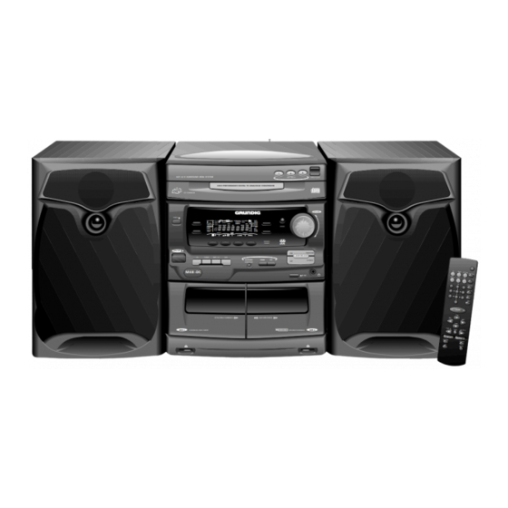
HiFi A/V SURROUND MINI SYSTEM
DISC SELECT
HIGH PERFORMANCE DIGITAL TO ANALOGUE CONVERSION
2
3
1
CD CHANGER
TIMER
CD TAPE
1
FRONT
D PRO LOGIC
D 3 STEREO
PLAY
CD
STEREO
BACK
PHANTOM
PROG
MODE
2
NORMAL
RECORD
DBB
PROGRAM
3
D NR
SHUFFLE
TIMER SET
SW
LW
FMMW
HSD
REC
AMPM
TIMER
SET CLOCK
DEMO
DUBBING
SIDE
BAND
RDS
SHUFFLE
MODE
TIMER
CLEAR
PRESET
TUNING
INFRARED
SENSOR
R D S
ON/OFF
ON
DOLBY PRO LOGIC
CD
TUNER
TAPE 1/2
AUX
INCREDIBLE
DBB
DSC
OFF
SURROUND
M48 -DC
B NR
SYNCHRO DUBBING
AUTOREVERSE
TAPE 1
PLAYBACK/LOGIC DRIVE
DOLBY B NR
RECORD/PLAYBACK
OPEN/CLOSE
VOLUME
PHANTOM
3-STEREO
TAPE 2
HiFi
M 18-C
M 28-C
M 38-C
M 48-DC
Btx * 32700 #
Sachnummer
Part Number 72010-755.85
Änderungen vorbehalten
Subject to alteration
Printed in Germany
VK233 1197
Advertisement

Related Manuals for Grundig M 18-C


Summary of Contents for Grundig M 18-C
- Page 1 Service Manual HiFi M 18-C Grundig Service M 28-C Hotline Deutschland... M 38-C ...Mo.-Fr. 8.00-16.30 Uhr Technik: M 48-DC TV/SAT 0180/52318-41 VCR/LiveCam 0180/52318-42 HiFi/Audio 0180/52318-43 Car Audio 0180/52318-44 Telekommunikation 0180/52318-45 Fax: 0180/52318-51 Ersatzteil-Bestellannahme: 0180/52318-40 Telefon: 0180/52318-50 Fax: HiFi A/V SURROUND MINI SYSTEM...
- Page 2 CD Changer CDC 3 MG ............4 - 39 NF-Teil M 18-C, M 28-C, M 38-C ........4 - 45 AF Part M 18-C, M 28-C, M 38-C ........4 - 45 NF-Teil M 48-DC ..............4 - 49 AF Part M 48-DC ..............4 - 49 DPL-Platte (nur M 48-DC) ...........
-
Page 3: General Section
Signal-to-noise ratio ............≥ 75dB Eingangsempfindlichkeit Aux ..........400mV Input sensitivity Aux ............400mV Lautsprecher M 18-C, M 28-C, M 38-C ........3Ω Speakers M 18-C, M 28-C, M 38-C .......... 3Ω Lautsprecher M 48-DC ............≥ 6Ω Speakers M 48-DC ..............≥ 6Ω... -
Page 4: Disassembly Instructions
Allgemeiner Teil / General Section M 18-C … M 48-DC Ausbauhinweise Disassembly Instructions 1. Öffnen des Gehäuses 1. Removing the cover - Die jeweils 6 Schrauben in den Gehäuseseitenwänden sowie die - Undo 6 screws on each side of the cover and 9 screws in the back 9 Schrauben in der Gehäuserückwand herausschrauben und das... - Page 5 - Beim Wiedereinsetzen auf richtigen Sitz des Steckverbinders - When reassembling take care of the correct position of the connec- achten! 8. Ausbau der NF-Verstärkerplatte (M 18-C) 8. Removing the AF Amplifier Board (M 18-C) - 2 Schrauben und 2 Schrauben (Fig. 9) herausschrauben und...
- Page 6 Allgemeiner Teil / General Section M 18-C … M 48-DC 9. Ausbau der Endstufe (M 28-C) 9. Removing the Power Amplifier (M 28-C) - 9 Schrauben herausschrauben (Fig. 12). - Undo 9 screws (Fig. 12). - Endstufe komplett mit Kühlkörper und Abdeckung abnehmen.
- Page 7 M 18-C … M 48-DC Allgemeiner Teil / General Section 12. Ausbau der Netzanschlußplatte (M 38-C) 12. Removing the Mains Connector Board (M 38-C) - Schraube (Fig. 17) und Schraube (Fig. 18) herausschrauben. - Undo screw (Fig. 17) and screw (Fig.
- Page 8 Allgemeiner Teil / General Section M 18-C … M 48-DC 15. Ausbau der Netzteilplatte (M 38-C) 15. Removing the Power Supply Board (M 38-C) - Netzteil / NF-Verstärker Einheit ausbauen (Pkt. 13). - Remove the Power Supply / AF Amplifier Module (para 13).
- Page 9 M 18-C … M 48-DC Allgemeiner Teil / General Section 17. Ausbau der Endstufe (M 48-DC) 17. Removing the Power Amplifier (M 48-DC) - 9 Schrauben herausschrauben (Fig. 26). - Undo 9 screws (Fig. 26). - Endstufe komplett mit Kühlkörper und Abdeckung abnehmen.
- Page 10 Allgemeiner Teil / General Section M 18-C … M 48-DC 20. CD-Laufwerk zerlegen 20. Disassembling the CD Drive - Laufwerk ausbauen (Pkt. 2). - Remove the drive (para 2). - Schublade bis zum Anschlag herausziehen. - Open drawer until the stop.
- Page 11 M 18-C … M 48-DC Allgemeiner Teil / General Section 22. Pick-Up-Einheit ausbauen 22. Remove the pick up unit - CD-Leiterplatte ausbauen (Pkt. 21). - Remove the CD PCB (para 21). - 2 Schrauben (Fig. 35) herausschrauben und die Halterungen - Undo 2 screws (Fig.
- Page 12 Allgemeiner Teil / General Section M 18-C … M 48-DC 25. Schubladenantrieb zerlegen 25. Disassemble the drive mechanism of the drawer - Schubladenantrieb ausbauen (Pkt. 23). - Remove the mechanism (para 23). - Die Zahrräder können nach Abziehen der entsprechenden Schei- - After pulling off the washers (Fig.
- Page 13 Einfetten grease die Nut einfetten grease inside groove auf der Oberseite einfetten grease on top of rib einfetten grease einfetten grease Oberfläche der 4 Rechtecke einfetten die Schieber einfetten grease on 4 rectangular surfaces grease on slide die 4 Nuten einfetten die Nuten einfetten grease on 4 profile groves einfetten...
- Page 14 Allgemeiner Teil / General Section M 18-C … M 48-DC Fig. 44 27. Removing the Drive Mechanisms (Fig. 44) 27. Ausbau der Cassettenlaufwerke (Fig. 44) - Remove the front panel (para 3). - Die Frontblende ausbauen (Pkt. 3). - Unscrew 4 screws (long).
- Page 15 M 18-C … M 48-DC Allgemeiner Teil / General Section Fig. 49 Fig. 50 Laufwerk 2 Laufwerk 1 Laufwerk 2 Laufwerk 1 Drive Mechanism 2 Drive Mechanism 1 Drive Mechanism 2 Drive Mechanism 1 30. Ausbau des Motors (Fig. 49 / 50) 30.
- Page 16 Allgemeiner Teil / General Section M 18-C … M 48-DC Service-Test-Programm Service Test Program Service-Test-Programm aktivieren Activation of Service Test Program Tasten "C4" und "B1" (siehe Abb. unten) gedrückt halten und Netzstek- Hold the buttons "C4" and "B1" (see figure below) depressed while plug ker einstecken.
- Page 17 M 18-C … M 48-DC Allgemeiner Teil / General Section 32kHz / 8MHz - Test 32kHz / 8MHz Test Taste "TIMER " drücken: Display zeigt "32K". Am Pin 80 von IC7401 Press button "TIMER ": The display shows "32K". 2048Hz can be sind 2048Hz meßbar.
- Page 18 Allgemeiner Teil / General Section M 18-C … M 48-DC CD-Servo-Test CD Servo Test Taste "CD" drücken -> Display zeigt "CD TEST". Press button "CD" -> The display shows "CD TEST". - Schlittentest: - Slide test: Taste "T" drücken -> Display zeigt "SLD 0" und der Pickup- Press button "T"...
- Page 19 BEDIENELEMENTE M 48-DC BEDIENELEMENTE M 18-C, M 28-C, M 38-C ON/OFF – Zum Einschalten des Gerätes und zum ON/OFF – Zum Einschalten des Gerätes und zum Umschalten auf Bereitschaftsbetrieb. Umschalten auf Bereitschaftsbetrieb. SOURCE SELECTION – Zum Wählen von: SOURCE SELECTION – Zum Wählen von: TUNER : Radiobetrieb.
- Page 20 BEDIENUNG DES SYSTEMS M 18-C, M 28-C, M 38-C BEDIENUNG DES SYSTEMS M 48-DC Sound control Klangkontrolle VOLUME Einstellen der Lautstärke Einstellen der Lautstärke VOLUME TIMER • Den Lautstärkeregler VOLUME nach links oder • Drehen Sie den Lautstärkeregler VOLUME nach...
- Page 21 TUNER TUNER Abstimmen auf Vorwahlsender Speichern von Vorwahlsendern Wenn das Gerät auf einen RDS-Sender abgestimmt • Drücken Sie die Taste PRESET 4 oder 3 (oder Ç ist, werden das RDS-Logo ( ) und der Sendername Es können bis zu 20 Sender gespeichert werden. Wenn VOLUME PREV ¡...
- Page 22 CD-WECHSLER CD-WECHSLER Wiedergabe einer Platte Suchen nach einer bestimmten Warnung! Passage während der Wiedergabe 1 Drücken Sie die Taste B (oder PLAY 2 auf der 1 Dieses Gerät ist für herkömmliche CDs HiFi A/V SURROUND MINI SYSTEM FRONT DISC SELECT OPEN/CLOSE Fernbedienung), um die Wiedergabe zu starten.
- Page 23 – to open TAPE 1 cassette compartment. – to open TAPE 1 cassette compartment. 19 TAPE DECK 1 19 TAPE DECK 1 REMOTE CONTROL M 18-C, M 28-C, M 38-C REMOTE CONTROL M 48-DC Inserting the batteries into the Inserting the batteries into the –...
- Page 24 OPERATING THE SYSTEM M 18-C, M 28-C, M 38-C OPERATING THE SYSTEM M 48-DC Sound control Sound control VOLUME Volume Adjustment VOLUME Volume Adjustment TIMER • Rotate VOLUME right or left (or press • Rotate VOLUME right or left (or press VOLUME +...
- Page 25 TUNER TUNER Storing Preset Stations Tuning to Preset Stations When you have tuned to an RDS station, the RDS Ç logo ( ) and the station name will appear on the • Press PRESET 4 or 3 (or PREV ¡ or NEXT ™ on You can store up to 20 stations in the memory.
- Page 26 CD CHANGER CD CHANGER Playing a Disc Searching for a particular passage Warning! during playback 1 Press B (or PLAY 2 on the remote control) to 1 This set is designed for conventional CDs. Do HiFi A/V SURROUND MINI SYSTEM FRONT DISC SELECT OPEN/CLOSE...
-
Page 27: Power Supply
M 18-C … M 48-DC Schaltungsbeschreibung / Circuit Desription Schaltungsbeschreibung M 28-C, M 48-DC Circuit Description M 28-C, M 48-DC Netzteil Power Supply Beschreibung: Circuit details: • Low Power Standby (nur M 48-DC) • Low power standby feature (only M 48-DC) - Page 28 Schaltungsbeschreibung / Circuit Desription M 18-C … M 48-DC • Temperaturüberwachung • Temperature monitoring In der Sekundärwicklung (Pin 8/9) des Netztransformators ist ein The mains transformer is equipped with a NTC, embedded in the NTC eingebaut. Über die NTC-Leitung wird die Temperatur des secondary winding (pin 8/9).
- Page 29 M 18-C … M 48-DC Schaltungsbeschreibung / Circuit Desription • Super Class G - Betrieb • Super class G - operation Die Leistungsverstärker arbeiten als sogenannte Super Class G - The power amplifiers operate as so-called super class G - amplifi- Verstärker:...
- Page 30 Schaltungsbeschreibung / Circuit Desription M 18-C … M 48-DC 1205 M 28-C 1008 4,5V 10,5V 6204 1203 1N5392 6,5V 6205 6,5V 1204 1N5392 10,5V 2206 100n Signal path D5SBA20 pos. halfwave 6201 100n 6201 neg. halfwave D5SBA20 2211 Fig. 1...
- Page 31 M 18-C … M 48-DC Schaltungsbeschreibung / Circuit Desription 1205 M 48-DC 1008 4,5V 6202 1N5392 10,5V 6203 1203 1N5392 6,5V 6204 6,5V 1204 1N5392 10,5V 6205 1N5392 2206 100n Signal path D5SBA20 pos. halfwave 6201 100n 6201 neg. halfwave...
- Page 32 Abgleichvorschriften / Adjustment Procedures M 18-C … M 48-DC Abgleichvorschriften 1. Tuner Meßgeräte: Meß-/Wobbelsender, Frequenzzähler, Oszilloskop, DC-Voltmeter, NF-Voltmeter Servicearbeiten nach Austausch des Frontends: Abgleich Nr. 6 Das Frontend ist ein komplett abgeglichener Baustein. Nur das ZF-Filter muß dem ZF-Verstärker angeglichen werden.
- Page 33 M 18-C … M 48-DC Abgleichvorschriften / Adjustment Procedures 2. Cassettenteil Meßgeräte/Meßmittel: NF-Voltmeter, Frequenzzähler, NF-Generator, Testkassette 448A Sach-Nr.: 35079-023.00 Abgleich Vorbereitung Abgleichvorgang 1. Azimut Cassettenfachdeckel abnehmen (Ausbau Pkt. 5). Die Ein- stellschrauben sind nun durch Aussparungen in den Cassettenklappen zugänglich.
-
Page 34: Adjustment Procedures
Abgleichvorschriften / Adjustment Procedures M 18-C … M 48-DC Adjustment Procedures 1. Tuner Measuring instruments: Standard/sweep signal generator, Frequency counter, Oscilloscope, DC voltmeter, AF voltmeter Service works after replacing the front end: Alignment no. 6 The front end is a completely adjusted module. Only the IF filter is to be tuned to the IF amplifier. - Page 35 M 18-C … M 48-DC Abgleichvorschriften / Adjustment Procedures 2. Tape Decks Measuring instruments/Test equipment: AF voltmeter, Frequency counter, AF generator, test cassette 448A Part No.: 35079-023.00 Alignment Preparation Procedure 1. Azimuth Remove the cassette lid cover (disassembly instructions para 5). The adjustment screws can now be set through the holes in the cassette lid.
- Page 36 Abgleichvorschriften / Adjustment Procedures M 18-C … M 48-DC Notizen / Notes 3 - 5 GRUNDIG Service...
- Page 37 Schaltpläne und Druckplattenabbildungen / Circuit Diagrams and Layout of PCBs Schaltpläne und Druckplattenabbildungen / Circuit Diagrams and Layout of PCBs Blockschaltplan M 28-C, M 48-DC / Block Diagram M 28-C, M 48-DC Blockschaltplan M 18-C, M 38-C / Block Diagram M 18-C, M 38-C GRUNDIG Service 4 - 1...
- Page 38 M 18-C … M 48-DC Schaltpläne und Druckplattenabbildungen / Circuit Diagrams and Layout of PCBs M 18-C … M 48-DC Verdrahtungsplan M 18-C / Wiring Diagram M 18-C Verdrahtungsplan M 28-C, M 48-DC / Wiring Diagram M 28-C, M 48-DC 4 - 3...
- Page 39 Schaltpläne und Druckplattenabbildungen / Circuit Diagrams and Layout of PCBs M 18-C … M 48-DC Schaltpläne und Druckplattenabbildungen / Circuit Diagrams and Layout of PCBs Verdrahtungsplan M 38-C / Wiring Diagram M 38-C Display M 18-C, M 28-C, M 38-C Display M 48-DC GRUNDIG Service 4 - 5...
- Page 40 Schaltpläne und Druckplattenabbildungen / Circuit Diagrams and Layout of PCBs M 18-C … M 48-DC Schaltpläne und Druckplattenabbildungen / Circuit Diagrams and Layout of PCBs M 18-C … M 48-DC Blockschaltplan Tuner / Block Diagram Tuner IF-AM IF-AM AM-DET 10,7MHz...
- Page 41 M 18-C … M 48-DC Schaltpläne und Druckplattenabbildungen / Circuit Diagrams and Layout of PCBs M 18-C … M 48-DC Schaltpläne und Druckplattenabbildungen / Circuit Diagrams and Layout of PCBs Schaltplan Tuner / Circuit Diagram Tuner Bauteile X Components 1102...
- Page 42 Schaltpläne und Druckplattenabbildungen / Circuit Diagrams and Layout of PCBs M 18-C … M 48-DC Schaltpläne und Druckplattenabbildungen / Circuit Diagrams and Layout of PCBs M 18-C … M 48-DC Duckplatte Tuner / Tuner PCB Für die tatsächliche Bauteilbestückung ist das Schaltbild maßgebend! The circuit diagram is relevant for the actual component assembly! Bestückungsseite / Component Side...
- Page 43 Schaltpläne und Druckplattenabbildungen / Circuit Diagrams and Layout of PCBs M 18-C … M 48-DC Schaltpläne und Druckplattenabbildungen / Circuit Diagrams and Layout of PCBs Schaltplan Front M 18-C, M 28-C, M 38-C / Circuit Diagram Front M 18-C, M 28-C, M 38-C Bauteile X 3466...
- Page 44 Schaltpläne und Druckplattenabbildungen / Circuit Diagrams and Layout of PCBs M 18-C … M 48-DC Druckplatte Front M 18-C, M 28-C, M 38-C / Front PCB M 18-C, M 28-C, M 38-C Bestückungsseite / Component Side Für die tatsächliche Bauteilbestückung ist das Schaltbild maßgebend!
- Page 45 M 18-C … M 48-DC Schaltpläne und Druckplattenabbildungen / Circuit Diagrams and Layout of PCBs Druckplatte Front M 18-C, M 28-C, M 38-C / Front PCB M 18-C, M 28-C, M 38-C Lötseite / Solder Side Für die tatsächliche Bauteilbestückung ist das Schaltbild maßgebend!
- Page 46 Schaltpläne und Druckplattenabbildungen / Circuit Diagrams and Layout of PCBs M 18-C … M 48-DC Schaltpläne und Druckplattenabbildungen / Circuit Diagrams and Layout of PCBs M 18-C … M 48-DC Schaltplan Front M 48-DC / Circuit Diagram Front M 48-DC...
- Page 47 M 18-C … M 48-DC Schaltpläne und Druckplattenabbildungen / Circuit Diagrams and Layout of PCBs M 18-C … M 48-DC Schaltpläne und Druckplattenabbildungen / Circuit Diagrams and Layout of PCBs Druckplatte Front M 48-DC / Front PCB M 48-DC Bestückungsseite / Component Side Für die tatsächliche Bauteilbestückung ist das Schaltbild maßgebend!
- Page 48 Schaltpläne und Druckplattenabbildungen / Circuit Diagrams and Layout of PCBs M 18-C … M 48-DC Schaltpläne und Druckplattenabbildungen / Circuit Diagrams and Layout of PCBs M 18-C … M 48-DC Druckplatte Front M 48-DC / Front PCB M 48-DC Lötseite / Solder Side Für die tatsächliche Bauteilbestückung ist das Schaltbild maßgebend!
- Page 49 M 18-C … M 48-DC Schaltpläne und Druckplattenabbildungen / Circuit Diagrams and Layout of PCBs M 18-C … M 48-DC Schaltpläne und Druckplattenabbildungen / Circuit Diagrams and Layout of PCBs Schaltplan Cassettenteil / Circuit Diagram Tape Part Bauteile X Components...
- Page 50 Schaltpläne und Druckplattenabbildungen / Circuit Diagrams and Layout of PCBs M 18-C … M 48-DC Schaltpläne und Druckplattenabbildungen / Circuit Diagrams and Layout of PCBs M 18-C … M 48-DC Schaltplan Cassettenteil / Circuit Diagram Tape Part Bauteile X 3717...
- Page 51 M 18-C … M 48-DC Schaltpläne und Druckplattenabbildungen / Circuit Diagrams and Layout of PCBs Druckplatte Cassettenteil / Tape PCB Bestückungsseite / Component Side 1701 3706 2765 2712 2716 3785 3764 3773 9707 2701 2703 9721 9711 9731 2702 9706...
- Page 52 Schaltpläne und Druckplattenabbildungen / Circuit Diagrams and Layout of PCBs M 18-C … M 48-DC Druckplatte Cassettenteil / Tape PCB Lötseite / Solder Side 3721 3722 3723 3724 3725 3726 3727 3728 3729 3730 3731 3732 270 4 3733 3734...
- Page 53 M 18-C … M 48-DC Schaltpläne und Druckplattenabbildungen / Circuit Diagrams and Layout of PCBs M 18-C … M 48-DC Schaltpläne und Druckplattenabbildungen / Circuit Diagrams and Layout of PCBs Blockschaltplan CD-Wechsler CDC 3 DH / Block Diagram CD Changer CDC 3 DH Verdrahtungsplan CD-Wechsler CDC 3 DH / Wiring Diagram CD Changer CDC 3 DH CDC 3 DH bei allen Geräte bis Ser.-Nr.
- Page 54 Schaltpläne und Druckplattenabbildungen / Circuit Diagrams and Layout of PCBs M 18-C … M 48-DC Schaltpläne und Druckplattenabbildungen / Circuit Diagrams and Layout of PCBs M 18-C … M 48-DC CDC 3 DH bei allen Geräte bis Ser.-Nr. 001047 Schaltplan CD-Wechsler CDC 3 DH / Circuit Diagram CD Changer (CDC Board) CDC 3 DH CDC 3 DH at all sets until serial no.
- Page 55 M 18-C … M 48-DC Schaltpläne und Druckplattenabbildungen / Circuit Diagrams and Layout of PCBs M 18-C … M 48-DC Schaltpläne und Druckplattenabbildungen / Circuit Diagrams and Layout of PCBs Druckplatte CD-Wechsler CDC 3 DH / PCB CD Changer Board (CDC Board) CDC 3 DH Bestückungsseite / Component Side...
- Page 56 Schaltpläne und Druckplattenabbildungen / Circuit Diagrams and Layout of PCBs M 18-C … M 48-DC Schaltpläne und Druckplattenabbildungen / Circuit Diagrams and Layout of PCBs M 18-C … M 48-DC Blockschaltplan CD-Wechsler CDC 3 MG / Block Diagram CD Changer CDC 3 MG Verdrahtungsplan CD-Wechsler CDC 3 MG / Wiring Diagram CD Changer CDC 3 MG CDC 3 DH bei allen Geräte bis Ser.-Nr.
- Page 57 M 18-C … M 48-DC Schaltpläne und Druckplattenabbildungen / Circuit Diagrams and Layout of PCBs M 18-C … M 48-DC Schaltpläne und Druckplattenabbildungen / Circuit Diagrams and Layout of PCBs CDC 3 MG bei allen Geräte ab Ser.-Nr. 001048 Schaltplan CD-Wechsler CDC 3 MG / Circuit Diagram CD Changer (CDC Board) CDC 3 MG CDC 3 MG at all sets from serial no.
- Page 58 Schaltpläne und Druckplattenabbildungen / Circuit Diagrams and Layout of PCBs M 18-C … M 48-DC Schaltpläne und Druckplattenabbildungen / Circuit Diagrams and Layout of PCBs M 18-C … M 48-DC CDC 3 MG bei allen Geräte ab Ser.-Nr. 001048 Schaltplan CD-Wechsler CDC 3 MG / Circuit Diagram CD Changer (CDC Board) CDC 3 MG CDC 3 MG at all sets from serial no.
- Page 59 M 18-C … M 48-DC Schaltpläne und Druckplattenabbildungen / Circuit Diagrams and Layout of PCBs M 18-C … M 48-DC Schaltpläne und Druckplattenabbildungen / Circuit Diagrams and Layout of PCBs CDC 3 MG bei allen Geräte ab Ser.-Nr. 001048 Druckplatte CD-Wechsler CDC 3 MG / PCB CD Changer Board (CDC Board) CDC 3 MG CDC 3 MG at all sets from serial no.
- Page 60 M 18-C … M 48-DC Schaltpläne und Druckplattenabbildungen / Circuit Diagrams and Layout of PCBs M 18-C … M 48-DC Schaltplan NF-Teil M 18-C, M 28-C, M 38-C / Circuit Diagram AF Part M 18-C, M 28-C, M 38-C 3540 3541...
- Page 61 Schaltpläne und Druckplattenabbildungen / Circuit Diagrams and Layout of PCBs Druckplatte NF-Teil M 18-C, M 28-C, M 38-C / PCB AF Part M 18-C, M 28-C, M 38-C Druckplatte NF-Teil M 18-C, M 28-C, M 38-C / PCB AF Part M 18-C, M 28-C, M 38-C Bestückungsseite / Component Side...
- Page 62 Schaltpläne und Druckplattenabbildungen / Circuit Diagrams and Layout of PCBs M 18-C … M 48-DC Schaltpläne und Druckplattenabbildungen / Circuit Diagrams and Layout of PCBs M 18-C … M 48-DC Schaltplan NF-Teil M 48-DC / Circuit Diagram AF Part M 48-DC...
- Page 63 M 18-C … M 48-DC Schaltpläne und Druckplattenabbildungen / Circuit Diagrams and Layout of PCBs M 18-C … M 48-DC Schaltpläne und Druckplattenabbildungen / Circuit Diagrams and Layout of PCBs Druckplatte NF-Teil M 48-DC / PCB AF Part M 48-DC Druckplatte NF-Teil M 48-DC / PCB AF Part M 48-DC Bestückungsseite / Component Side...
- Page 64 Schaltpläne und Druckplattenabbildungen / Circuit Diagrams and Layout of PCBs M 18-C … M 48-DC Schaltpläne und Druckplattenabbildungen / Circuit Diagrams and Layout of PCBs M 18-C … M 48-DC Schaltplan DPL-Platte M 48-DC / Circuit Diagram DPL Board M 48-DC...
- Page 65 M 18-C … M 48-DC Schaltpläne und Druckplattenabbildungen / Circuit Diagrams and Layout of PCBs M 18-C … M 48-DC Schaltpläne und Druckplattenabbildungen / Circuit Diagrams and Layout of PCBs Druckplatte DPL-Platte M 48-DC / PCB DPL Board M 48-DC Druckplatte DPL-Platte M 48-DC / PCB DPL Board M 48-DC Bestückungsseite / Component Side...
- Page 66 Schaltpläne und Druckplattenabbildungen / Circuit Diagrams and Layout of PCBs M 18-C … M 48-DC Schaltpläne und Druckplattenabbildungen / Circuit Diagrams and Layout of PCBs M 18-C … M 48-DC Schaltbild Netzteil und Endstufe M 18-C / Circuit Diagram Power Supply and Power Amplifier M 18-C 2221 100n D3SBA20...
- Page 67 M 18-C … M 48-DC Schaltpläne und Druckplattenabbildungen / Circuit Diagrams and Layout of PCBs Druckplatten Netzteil und Endstufe M 18-C / PCBs Power Supply and Power Amplifier M 18-C Für die tatsächliche Bauteilbestückung ist das Schaltbild maßgebend! The circuit diagram is relevant for the actual component assembly!
- Page 68 Schaltpläne und Druckplattenabbildungen / Circuit Diagrams and Layout of PCBs M 18-C … M 48-DC Schaltpläne und Druckplattenabbildungen / Circuit Diagrams and Layout of PCBs M 18-C … M 48-DC Schaltbild Netzteil und Endstufe M 28-C / Circuit Diagram Power Supply and Power Amplifier M 28-C...
- Page 69 M 18-C … M 48-DC Schaltpläne und Druckplattenabbildungen / Circuit Diagrams and Layout of PCBs M 18-C … M 48-DC Schaltpläne und Druckplattenabbildungen / Circuit Diagrams and Layout of PCBs Druckplatten Netzteil und Endstufe M 28-C / PCBs Power Supply and Power Amplifier M 28-C Für die tatsächliche Bauteilbestückung ist das Schaltbild maßgebend!
- Page 70 Schaltpläne und Druckplattenabbildungen / Circuit Diagrams and Layout of PCBs M 18-C … M 48-DC Schaltpläne und Druckplattenabbildungen / Circuit Diagrams and Layout of PCBs M 18-C … M 48-DC Schaltbild Netzteil M 38-C / Circuit Diagram Power Supply M 38-C...
- Page 71 M 18-C … M 48-DC Schaltpläne und Druckplattenabbildungen / Circuit Diagrams and Layout of PCBs M 18-C … M 48-DC Schaltpläne und Druckplattenabbildungen / Circuit Diagrams and Layout of PCBs Druckplatten Netzteil und Endstufe M 38-C / PCBs Power Supply and Power Amplifier M 38-C Für die tatsächliche Bauteilbestückung ist das Schaltbild maßgebend!
- Page 72 Schaltpläne und Druckplattenabbildungen / Circuit Diagrams and Layout of PCBs M 18-C … M 48-DC Schaltpläne und Druckplattenabbildungen / Circuit Diagrams and Layout of PCBs M 18-C … M 48-DC Schaltbild Endstufe M 38-C / Circuit Diagram Power Amplifier M 38-C...
- Page 73 M 18-C … M 48-DC Schaltpläne und Druckplattenabbildungen / Circuit Diagrams and Layout of PCBs M 18-C … M 48-DC Schaltpläne und Druckplattenabbildungen / Circuit Diagrams and Layout of PCBs Schaltbild Endstufe M 48-DC / Circuit Diagram Power Amplifier M 48-DC...
- Page 74 Schaltpläne und Druckplattenabbildungen / Circuit Diagrams and Layout of PCBs M 18-C … M 48-DC Schaltpläne und Druckplattenabbildungen / Circuit Diagrams and Layout of PCBs M 18-C … M 48-DC Schaltbild Endstufe M 48-DC / Circuit Diagram Power Amplifier M 48-DC...
- Page 75 M 18-C … M 48-DC Schaltpläne und Druckplattenabbildungen / Circuit Diagrams and Layout of PCBs M 18-C … M 48-DC Schaltpläne und Druckplattenabbildungen / Circuit Diagrams and Layout of PCBs Druckplatten Netzteil und Endstufe M 48-DC / PCBs Power Supply and Power Amplifier M 48-DC Für die tatsächliche Bauteilbestückung ist das Schaltbild maßgebend!
- Page 76 Ersatzteillisten und Explosionszeichnungen / Spare Parts Lists and Exploded Views M 18-C … M 48-DC Ersatzteillisten und Explosionszeichnungen / Spare Parts Lists and Exploded Views Explosionszeichnung M 18-C / Exploded View M 18-C 5 - 1 GRUNDIG Service 5 - 2...
- Page 77 POS. NR. SACHNUMMER BEZEICHNUNG POS. NR. SACHNUMMER BEZEICHNUNG POS. NR. SACHNUMMER BEZEICHNUNG POS. NR. SACHNUMMER BEZEICHNUNG POS. NO. PART NUMBER DESCRIPTION POS. NO. PART NUMBER DESCRIPTION POS. NO. PART NUMBER DESCRIPTION POS. NO. PART NUMBER DESCRIPTION T 7406 8301-006-847 SMD-TRANS.BC 847 C T 7634 8301-006-848 SMD-TRANS.BC 848 C...
- Page 79 POS. NR. ABB. SACHNUMMER ANZ. BEZEICHNUNG DESCRIPTION © POS. NO. FIG. PART NUMBER QTY. Ersatzteilliste AUDIO / HIFI Spare Parts List 035.000 75954-049.04 SCHALTER BETRIEBSART SWITCH MODE 039.000 75954-049.05 BLATTSCHALTER LEAF SWITCH 042.000 75954-049.07 RIEMEN BELT 099.000 75954-049.70 REFLEXLICHT-SCHRANKE REFLEX LIGHT BARRIER 11 / 97 M 28-C LAUFWERK B/2...
- Page 80 POS. NR. SACHNUMMER BEZEICHNUNG POS. NR. SACHNUMMER BEZEICHNUNG POS. NR. SACHNUMMER BEZEICHNUNG POS. NR. SACHNUMMER BEZEICHNUNG POS. NO. PART NUMBER DESCRIPTION POS. NO. PART NUMBER DESCRIPTION POS. NO. PART NUMBER DESCRIPTION POS. NO. PART NUMBER DESCRIPTION T 7417 8301-006-847 SMD-TRANS.BC 847 C T 7652 8301-006-848 SMD-TRANS.BC 848 C...
- Page 82 POS. NR. ABB. SACHNUMMER ANZ. BEZEICHNUNG DESCRIPTION © POS. NO. FIG. PART NUMBER QTY. Ersatzteilliste AUDIO / HIFI Spare Parts List 023.000 75954-049.03 TAUCHANKERMAGNET KPL. SOLENOID ASSY 035.000 75954-049.04 SCHALTER BETRIEBSART SWITCH MODE 039.000 75954-049.05 BLATTSCHALTER LEAF SWITCH 042.000 75954-049.07 RIEMEN BELT 099.000...
- Page 83 POS. NR. SACHNUMMER BEZEICHNUNG POS. NR. SACHNUMMER BEZEICHNUNG POS. NR. SACHNUMMER BEZEICHNUNG POS. NR. SACHNUMMER BEZEICHNUNG POS. NO. PART NUMBER DESCRIPTION POS. NO. PART NUMBER DESCRIPTION POS. NO. PART NUMBER DESCRIPTION POS. NO. PART NUMBER DESCRIPTION T 7417 8301-006-847 SMD-TRANS.BC 847 C T 7653 75951-022.78 CHIP TRANS.BC 807-40...
- Page 85 POS. NR. ABB. SACHNUMMER ANZ. BEZEICHNUNG DESCRIPTION © POS. NO. FIG. PART NUMBER QTY. Ersatzteilliste AUDIO / HIFI Spare Parts List 012.000 75954-049.02 ANDRUCKARM KPL., RECHTS PRESSURE ARM CPL, RIGHT 023.000 75954-049.03 TAUCHANKERMAGNET KPL. SOLENOID ASSY 035.000 75954-049.04 SCHALTER BETRIEBSART SWITCH MODE 039.000 75954-049.05...
- Page 86 POS. NR. SACHNUMMER BEZEICHNUNG POS. NR. SACHNUMMER BEZEICHNUNG POS. NR. SACHNUMMER BEZEICHNUNG POS. NR. SACHNUMMER BEZEICHNUNG POS. NO. PART NUMBER DESCRIPTION POS. NO. PART NUMBER DESCRIPTION POS. NO. PART NUMBER DESCRIPTION POS. NO. PART NUMBER DESCRIPTION R 3635 75953-701.12 POTI LIN 20KOHM D 6206 8309-215-045 DIODE 1N4148...
- Page 91 POS. NR. SACHNUMMER BEZEICHNUNG POS. NR. SACHNUMMER BEZEICHNUNG POS. NO. PART NUMBER DESCRIPTION POS. NO. PART NUMBER DESCRIPTION Ersatzteilliste HIFI Spare Parts List D 6871 8309-215-045 DIODE 1N4148 D 6872 8309-215-045 DIODE 1N4148 D 6873 8309-215-045 DIODE 1N4148 D 6874 8309-215-045 DIODE 1N4148 D 6875...
- Page 92 POS. NR. SACHNUMMER BEZEICHNUNG POS. NR. SACHNUMMER BEZEICHNUNG POS. NO. PART NUMBER DESCRIPTION POS. NO. PART NUMBER DESCRIPTION Ersatzteilliste AUDIO / HIFI Spare Parts List D 6871 8309-215-045 DIODE 1N4148 D 6872 8309-215-045 DIODE 1N4148 D 6873 8309-215-045 DIODE 1N4148 D 6874 8309-215-045 DIODE 1N4148...