Table of Contents
Advertisement
Advertisement
Table of Contents

Related Manuals for Sanwa MX-3X


Summary of Contents for Sanwa MX-3X
- Page 1 OPERATING MANUAL...
-
Page 2: Table Of Contents
Index ....................................Page 52 PACKAGING The packaging of your SANWA MX-3X 2.4GHz FHSS-3 radio control system has been specially designed for the safe transportation and storage of the radio control system's components. After unpacking your radio control system, do not discard the packaging materials. -
Page 3: Introduction
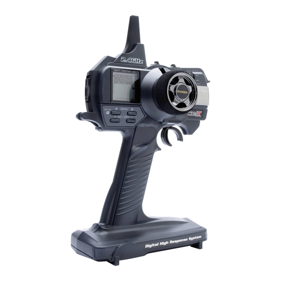
The MX-3X 2.4GHz FHSS-3 radio control system has been designed for the utmost in comfort and precise control of all types of model cars and boats. -
Page 4: Usage Precautions
USAGE PRECAUTIONS In addition to the Safety and FCC Compliance sections on the previous page, please observe the following precautions when installing and using your new SANWA MX-3X 2.4GHz FHSS-3 radio control system. 2.4GHZ FREQUENCY BAND PRECAUTIONS The 2.4GHz frequency band may be used by other devices, or other devices in the immediate area may cause interference on ... -
Page 5: Features And Specifications
Dimensions: 40.4 x 21.1 x 26.4mm Weight: 66gr Weight: 50gr Both analog and digital servos will work with your MX-3X 2.4GHz FHSS-3 radio control system. To get the most out of your experience, we recommend the use of digital servos. Page 5... -
Page 6: Features Familiarization
FEATURES FAMILIARIZATION FEATURES DIAGRAMS Use the diagrams below and on the next page to familiarize yourself with the different system controls on your new MX-3X 2.4GHz FHSS-3 transmitter and 92744 receiver. Descriptions of these features can be found on page 8. - Page 7 FEATURES FAMILIARIZATION BACK Power Switch Wrist Strap Anchor Charging Jack Throttle Trigger Adjustment Lock Screw Throttle Trigger Adjustment Indicator LEFT Power Switch Charging Jack 'Z' Connector - = Negative (Black) + = Positive (Red) S = Signal (Blue) Antenna Bind LED Coaxial Cable Reception Wire Bind Button...
-
Page 8: Features Descriptions
Bind Button and Bind LED: Used in the process of Binding the transmitter and receiver. Charging Jack: Used for onboard charging of the optional 6 cell 1500mAh Ni-MH battery. Do not attempt to charge Alkaline batteries. Only the recommended SANWA 100v AC charger should be used through the Charging Jack. -
Page 9: Tx And Rx Options And Connections
TRANSMITTER BATTERY OP` T IONS The MX-3X 2.4GHz FHSS-3 transmitter's Nominal Input Voltage is 4.8v ~ 7.2v. This means that the transmitter can be used with several different battery types, depending on your preference. -
Page 10: Using The Optional 6 Cell Ni-Mh Battery And 110V Ac Charger
USING THE optIONAL 6 CELL NI-MH BATTERY AND 110V AC CHARGER An optional SANWA 6 cell 1500mAh Ni-MH rechargeable battery and 100v 240v AC charger are available separately and can be used in place of the standard 4 cell Alkaline batteries. This option, while adding slightly more weight, still results in a lightweight, well-balanced transmitter, but provides much longer battery life with reduced cost over the life of the transmitter, since there is no need to continuously purchase 'AA' Alkaline batteries. -
Page 11: Warnings If Using A Li-Po Or Li-Fe Transmitter Battery
TX AND RX OPTIONS AND CONNECTIONS WARNINGS IF USING A LI-PO OR LI-FE TRANSMITTER BATTERY Use ONLY a 2 Cell Li-Po or Li-Fe battery pack of desired capacity. DO NOT USE A 3 CELL LI-PO OR LI-FE BATTERY PACK or the transmitter will be damaged. -
Page 12: Lcd And Programming Keys
LcD anD PROgRaMMing kEYS The MX-3X 2.4GHz FHSS-3 transmitter features four Programming Keys that are used to facilitate transmitter programming. The four Programming Keys consist of two MENU Keys (Right and Left), one +/INC (Increase) Key, and one DEC/- (Decrease) Key. -
Page 13: Programming Key Shortcuts
LCD AND PROGRAMMING KEYS PROGRAMMING KEY SHORTCUTS The Programming Keys can be used to change important information displayed in the Programming Window. The information that can be displayed will vary depending on what menu you're currently in and/or what is currently displayed in the Programming Window. -
Page 14: Menu Flow Chart
MEnU FLOw cHaRT The Menu Flow Chart shows the different menus that are available for programming your transmitter. The default setting when the transmitter is turned ON the very first time is the PROGRAMMING menu with the Digital Voltage Indicator displayed. When the transmitter is subsequently turned ON, the last screen displayed when the transmitter was turned OFF will be displayed. -
Page 15: Transmitter And Receiver Binding
ON. If this occurs, perform the Binding process again. The MX-3X 2.4GHz FHSS-3 radio control system uses FHSS-3 technology, however, the transmitter is compatible with both FHSS-3 and FHSS-2 SANWA 2.4GHz receivers. To bind the transmitter to an SANWA FHSS-2 2.4GHz receiver (available separately), the transmitter Modulation Type must first be changed to FH2. -
Page 16: Programming Menu
[ [ P ROGRAMMING MENU To enter the PROGRAMMING menu, turn the transmitter ON. when the transmitter is turned ON the very first time is the PROGRAMMIG menu with the Digital Voltage Indicator displayed.When the transmitter is subsequently turned ON, the last screen displayed when the transmitter was turned OFF will be displayed. -
Page 17: End Point Adjustment
PROGRAMMING MENU Adjusting Steering Dual Rate 1) Press the Right or Left MENU key to highlight the D/R menu. ST 100% will be displayed in the Programming Window. 2) Press the +/INC or DEC/- keys to increase or decrease the Steering Dual Rate percentage value. - Page 18 [ [ P ROGRAMMING MENU Adjusting Steering End Point Adjustment, Continued..1) Press the Right or Left MENU key to highlight the EPA menu. ST L 100% or ST R 100% will be displayed in the Programming Window depending on the last position of the steering wheel. 2) To set the Right Steering End Point Adjustment percentage value, turn and HOLD the steering wheel to the right.
- Page 19 [ [ P ROGRAMMING MENU Adjusting Throttle End Point Adjustment, Continued..3) To set the Throttle Brake End Point Adjustment percentage value, push and HOLD the throttle trigger forward. B 100% will be displayed. Press the +/INC or DEC/- keys to increase or decrease the amount of throttle servo travel in the Brake direction.
-
Page 20: Exponential
[ [ P ROgRaMMing MEnU ExP - ExPOnEnTiaL The Exponential function allows you to vary the amount of servo travel in relation to the movement of the steering wheel and the throttle trigger near the neutral positions to change the way the steering, throttle, and brake react to control movement. -
Page 21: Servo Speed
[ [ P ROgRaMMing MEnU Adjusting Throttle High Exponential, Continued..2) Press the +/INC or DEC/- keys to increase or decrease the Throttle High side Exponential percentage value. Decreasing the Throttle High Exponential percentage value will make the throttle less sensitive around neutral and increasing the Throttle High Exponential percentage value will make the throttle more sensitive around neutral. - Page 22 [ [ P ROgRaMMing MEnU Adjusting Steering Speed - Forward and Return to Center, Continued..2) Press the +/INC or DEC/- keys to decrease the Steering Speed Forward percentage value. Decreasing the Steering Speed Forward percentage value will cause the steering servo transit time to slow down in the Forward direction.
-
Page 23: Auxiliary Programming
[ [ P ROgRaMMing MEnU aUx - aUxiLiaRY PROgRaMMing The Auxiliary Programming function allows you to select, program, then use several different Mixes and other options specific to Auxiliary Channel 3. These include Point Auxiliary, Dig, Burn, Brake Mixing, and more. - Page 24 [ [ P ROgRaMMing MEnU Auxiliary Channel 3 ON-OFF, Continued..2) To control Auxiliary Channel 3, move the Auxiliary Lever UP (HIGH) and DOWN (LOW). When you move the Auxiliary Lever UP, HIGH will momentarily displayed in the Programming Window and the Auxiliary Channel 3 servo will travel to its High position. When you move the Auxiliary Lever DOWN, LOW will momentarily be displayed in the Programming Window and the Auxiliary Channel 3 servo will travel to its Low position.
- Page 25 [ [ P ROGRUMMING MENU Choosing the Number of Points, Continued..2) Press the +/INC or DEC/- keys to choose the number of Points you would like to program. You cannot choose fewer than 2 Points. AUX-P setting range is 2 to 6. The default setting is 6. Choosing Point Values Move the Auxiliary Lever to the ON position (pushed UP).
- Page 26 [ [ P ROgRaMMing MEnU S_ aUx - STEP aUxiLiaRY The Step Auxiliary function allows you to program Auxiliary Channel 3 to move in defined Step amounts throughout its entire range of travel. Step values can be defined, then you can move the Auxiliary Channel 3 servo in those Step amounts, using either the TRM switch or by pressing the +/INC and DEC/- keys.
- Page 27 [ [ P ROGRAMMING MENU Activating and u sing the Step Auxiliary Function, Continued..Press the +/INC or DEC/- keys to move the Auxiliary Channel 3 servo Right or Left by the defined Step value. In addition, Auxiliary Channel 3 servo travel in one direction can also be changed by pressing the Right MENU key. Step Auxiliary servo travel is -100 to 100 and overrides End Point Adjustments programmed through the EPA menu.
- Page 28 [ [ P ROgRaMMing MEnU Choosing the Steering Channel Option 1) From within the 4WS menu, press the Right MENU key. ST1 will be displayed in the Programming Window. 2) Press the +/INC or DEC/- keys to choose the desired Steering Channel option, either ST1 or ST2.
- Page 29 [ [ P ROGRAMMING MENU TRM Switch Assigning Auxiliary Channel 3 Steering Servo Trim to the TRM Switch 1) The ST-TRIM switch affects only the Right and Left trimming of the Channel 1 Steering servo. If desired, you can independently control the Right and Left trimming of the Auxiliary Channel 3 Steering servo.
- Page 32 [ [ P ROgRaMMing MEnU Choosing the Throttle Channel Option, Continued..Two Throttle Channel options are available as described below: TH1 - Exponential and Servo Speed settings affect Channel 2 Throttle Brake Side only. TH2 - Exponential and Servo Speed settings affect both Channel 2 and Auxiliary Channel 3 Throttle Brake Sides equally. Regardless of choice, Auxiliary Channel 3 Throttle servo Brake Side Exponential and Servo Speed are not adjustable separately.
-
Page 33: Fail Safe
[ [ P ROgRaMMing MEnU Choosing the Master Channel and Steering and Throttle Channel Options, Continued..2) Press the +/INC or DEC/- keys to choose the desired Master Channel and that specific Channel option. The Master channel is the channel you would like to Mix with Auxiliary Channel 3. For example, if your monster truck features dual Front steering servos, choose ST1 or ST2. -
Page 38: Model Select
[ [ P ROGRAMMING MENU Changing Auxiliary Channel 3 Servo Reversing 1) From within the REV menu, press the Right MENU key to highlight AUX NOR. 2) Press the +/INC or DEC/- keys to change the direction of Auxiliary Channel 3 servo travel. REV-AUX setting range is NOR and REV. -
Page 42: Setup Menu
SETUP MEnU Assigning TRM Switch Functions, Continued..2) Press the +/INC or DEC/- keys to display the desired Auxiliary function you would like to control with the TRM switch. TRM setting range is D/R, TH_HI, TH_BR, 3C_HI, 3C_LO, 3_SUB, P_AUX, AND S_AUX. The default setting is D/R. -
Page 43: Model Naming
SETUP MEnU Changing Steering and Throttle Trim Step Resolution, Continued..2) Press the +/INC key. ST S 5 will be displayed in the Programming Window. 3) Press the +/INC or DEC/- keys to choose the desired Trim Step Resolution value for the Steering Trim Switch. - Page 44 SETUP MEnU Naming Your Model, Continued..2) Press the Right or Left MENU key to highlight the AUX menu. NAME will be displayed in the Programming Window. 3) Press the +/INC or DEC/- keys once to enter the Model Naming screen. The cursor will flash in the lower left corner of the Programming Window and the current Model Name will be displayed.
-
Page 45: Model Clear
SETUP MEnU M_ c LR - MODEL cLEaR The Model Clear function allows you to reset the selected model's Programming Data to the default values. All model-specific Programming Data is reset. Transmitter-specific Programming Data, such as Audible Key Tone, Inactivity Alarm, and Battery Cell Count are not reset. Clearing Model Programming Data 1) Before clearing your Model Programming Data, use the Model Select function to choose and load the Programming Data for the particular model number (1~18) that you would like to clear... -
Page 46: Inactivity Alarm
SETUP MEnU Activating or Inhibiting Audible Key Tones, Continued..2) Press the +/INC or DEC/- keys to select ACT (Active) or INH (Inhibit). When set to ACT, an Audible Tone will sound when a Programming Key or a Trim Switch is pressed. When set to INH, no Audible Tone will sound when a Programming Key or a Trim Switch is pressed. - Page 47 SETUP MEnU Choosing the Battery Cell Count If you're using an optional rechargeable battery pack, to ensure that there are no issues when selecting the Battery Cell Count, you should first fully-charge your battery before installing it into the transmitter and choosing the Battery Cell Count. 1) Press the Right or Left MENU key to highlight the MODEL menu.
-
Page 54: Index
inDEx Modulation Type, Choosing 39 Modulation Type, Overview 39 Motor on Axle Mixing, Activating and Using 30 Motor on Axle Mixing, Assigning Auxiliary Channel 3 Throttle Servo Trim to TRM Switch 30 Motor on Axle Mixing, Changing Power Distribution 31 Motor on Axle Mixing, Choosing Throttle Options 29 Motor on Axle Mixing, Definition of 50 Motor on Axle Mixing, Overview 29... - Page 55 inDEx Servo Sub-Trim - Throttle, Adjusting 36 Servos, Using Analog and Digital 5 Setup Menu, Accessing 39 Setup Menu Icon, Definition of 51 Setup Menu Icon, Diagram of 12 Setup Menu, Menu Options 14 Specifications, Transmitter and Receiver 5 Steering Dual Rate, Assigning to TRM Switch 17 Steering Dual Rate, Centering the Steering Servo and Wheels 16 Steering Dual Rate, Definition of 51 Steering Dual Rate, Overview 15...
- Page 56 SANWA ELECTRONIC INSTRUMENT CO., LTD. 670A14203A...
Need help?
Do you have a question about the MX-3X and is the answer not in the manual?
Questions and answers