Nordyne B6BM Series Installation Instructions Manual
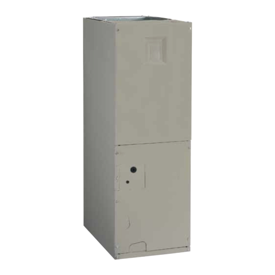
Air handler
Hide thumbs
Also See for B6BM Series:
- Installation instructions manual (32 pages) ,
- Installation instructions manual (32 pages)
Table of Contents
Advertisement
B6BM, B6EM, & B6VM Series
INSTALLATION INSTRUCTIONS
AIR HANDLER
Please read all information in this manual thoroughly and become familiar with the capabilities
and use of your appliance before attempting to operate or maintain this unit. These instructions
are primarily intended to assist qualified individuals experienced in the proper installation of
this appliance. Some local codes require licensed installation/service personnel for this type
of equipment. Improper installation, service, adjustment, or maintenance may cause explosion,
fire, electrical shock or other hazardous conditions which may result in personal injury or
property damage.
Unless otherwise noted in these instructions, only factory authorized kits or accessories may
be used with this product. Keep this manual where you have easy access to it in the future. If a
problem occurs, check the instructions and follow recommendations given. If these suggestions
don't eliminate your problem, call your servicing contractor.
IMPORTANT
DO NOT DESTROY. PLEASE READ CAREFULLY AND
KEEP IN A SAFE PLACE FOR FUTURE REFERENCE.
Advertisement
Table of Contents

Related Manuals for Nordyne B6BM Series


Summary of Contents for Nordyne B6BM Series
-
Page 1: Air Handler
B6BM, B6EM, & B6VM Series INSTALLATION INSTRUCTIONS AIR HANDLER IMPORTANT Please read all information in this manual thoroughly and become familiar with the capabilities and use of your appliance before attempting to operate or maintain this unit. These instructions are primarily intended to assist qualified individuals experienced in the proper installation of this appliance. -
Page 2: Table Of Contents
TABLE OF CONTENTS Important Safety Information ........3 Startup & Adjustments ..........13 Before You Start the Unit .........13 Requirements & Codes ..........3 Refrigerant Charging ..........14 General Information ...........4 Air Circulation ............14 Before You Install this Unit .........4 Running the Blower Continuously ......14 Locating the Air Handler ..........4 Selecting Continuous Low Spd Fan Operation .. -
Page 3: Important Safety Information
IMPORTANT SAFETY INFORMATION WARNING: INSTALLER: Please read all instructions before servicing this equipment. Pay attention to all safety warnings and PROPOSITION 65 WARNING: This product any other special notes highlighted in the manual. Safety contains chemicals known to the state of markings are used frequently throughout this manual to California to cause cancer, birth defects or designate a degree or level of seriousness and should not... -
Page 4: General Information
GENERAL INFORMATION Operation of Air Handler During Construction This appliance has been tested for capacity and efficiency CAUTION: in accordance with AHRI Standards and will provide many years of safe and dependable comfort, providing Failure to follow these instructions will void the it is properly installed and maintained. -
Page 5: Installation In A Garage
and cleaned of any construction debris, and the air as the opening provided on the air handler. The ducts handler must be cleaned and/or repaired if found to should be appropriately sized to the capacity of the air be dirty, damaged, or malfunctioning in any way by handler to ensure its proper airflow rating. -
Page 6: Air Handler Installation
handler may be used to reduce the transmission of equipment noise eminating from the air handler. These treatments can produce a quieter installation, particularly in the heated space. However, they can increase the pressure drop in the duct system. Care must be taken to maintain the proper maximum pressure rise across the air handler, temperature rise and flow rate. -
Page 7: Horizontal Installations
Horizontal Installations to the rafters with lag bolts. The air handler can also be The B6 Series air handler can be installed horizontally in suspended using steel straps around each end of the an attic, basement, crawl space or alcove. It can also be unit. -
Page 8: Refrigerant Line Connections
• Refrigerant lines should be wrapped with pressure NOTE: It is recommended that the suction line be insulated up to the coil inside of the cabinet. sensitive neoprene or other suitable material where they pass against sharp sheet metal edges. 7. -
Page 9: Connecting The Linsets
Connecting the Linesets IMPORTANT NOTES FOR HORIZONTAL OR DOWNFLOW INSTALLATIONS WITH TXV VALVE: • The sensing bulb must be located flush against the suction line for optimum heat transfer. • Avoid attaching the sensing bulb to the lowest part of the suction line where condensate may accumulate. -
Page 10: Condensate Drainage
• If the air handler is located in or above a living space 7. Wrap the refrigerant lines with pressure sensitive neoprene or other suitable material especially where where damage may result from condensate overflow, the lines enter the opening in the sheet metal. an auxiliary drain pan shall be installed under the unit. -
Page 11: Electrical Connections
• Use only copper wire for the line voltage power supply ELECTRICAL CONNECTIONS to this unit. Use proper code agency listed conduit and a conduit connector for connecting the supply wires to WARNING: the unit. Aluminum supply wire may be used if a heater ELECTRICAL SHOCK, FIRE OR EXPLOSION kit is installed. -
Page 12: Control Board
fireplaces, sunlight, or lighting fixtures, and convective Control Board heat from warm air registers or electrical appliances. The control board in the air handler controls the timing Refer to the thermostat manufacturer’s instruction sheet sequence of the elements. The board is equipped with a 3 for detailed mounting and installation information. -
Page 13: Heater Kits
NOTE: Variable speed air handlers cannot be twinned. STARTUP & ADjUSTMENTS Heater Kits When electric heat packages with circuit breakers are WARNING: field-installed, the circuit breaker may be used as a disconnecting means in most applications. Reference NITROGEN the NEC and local codes for disconnect requirements. HEALTH If a heater kit is installed: The B6BM air handler is shipped from the factory without... -
Page 14: Refrigerant Charging
5. Weigh in the proper amount of new (or reclaimed) energized along with a heat pump, the airflow may be higher refrigerant. Refer to the air conditioner or heat pump depending on the basic cooling/heat-pump airflow setting. installation manual for the proper type and quantity of The minimum electric heat airflow is selected by the red refrigerant. -
Page 15: High Efficiency Units (Var. & Fixed Speed)
• Terminal 4 = Hi speed • For maximum dehumidification, select an airflow near the • Terminal 5 = Med speed middle or bottom of the range for that nominal capacity. • Terminal 6 = Low speed Additional information on humidity control can be found in the Humidistat and Delay Setting sections. -
Page 16: Unit Maintenance
UNIT MAINTENANCE CABINET SIZE FILTER SIZE Proper maintenance is most important to achieve the best 12 x 20 x 1 performance from a air handler. Some of the components 18 x 20 x 1 and their locations are shown in Figure 12 (page 18). If 20 x 20 x 1 any component of the air handler must be replaced, use Table 2. -
Page 17: Figures & Tables
FIGURES & TABLES 3/4” 3/4” 3/4” 13” 11/8” K.O. (typ.) “A” 1 7/8" K.O. 11/4” 15/8” 11/4” 17/8” 3 1/4” 2 5/8” 1 1/8” 1 7/8” 11/8” K.O. 7/8" K.O. (typ.) 1 7/8” 3 5/8” 5 5/8” 13/4” K.O. (typ.) DETAIL “D”... -
Page 18: Figure 12. Air Handler Components
Circuit Breaker (60A) Heating Element Assembly Transformer Motor Control Board Blower Control Upper Door Wheel Board Assembly Capacitor Motor Mount Kit Blower Housing Blower Coil Motor Assembly Filter Door Horizontal Vertical Drain Pan Drain Pan Filter Tracks Lower Door Assembly Figure 12. -
Page 19: Airflow Data
AIRFLOW DATA Dry Coil ESP 0.10 0.20 0.30 0.40 0.50 0.60 0.70 0.80 Corrected ESP 0.00 0.07 0.19 0.30 0.42 0.53 0.65 0.76 Medium *24K A-Cabinet Corrected ESP 0.00 0.00 0.11 0.23 0.36 0.48 0.60 0.72 High 1072 1026 Corrected ESP 0.00 0.00 0.00... - Page 20 Cooling or Heating Airflow (CFM) Switch Settings 0 = OFF, 1 = ON Dry Coil ESP 1/5 2/6 3/7 4/8 1030 B6EM 1115 1085 1060 1020 A-cabinet 1155 1130 1095 1070 1040 1010 1200 1175 1145 1110 1085 1060 1025 1000 1240 1215...
- Page 21 Nominal Electic Heat KW Cabinet 1000 1300 1000 1100 1300 1500 1000 1100 1200 1400 1600 1800 2000 NOTE: See Table 6 for appropriate switch settings for these airflows. Table 7. Minimum Heating Airflow Settings (in CFM) for B6EM (FSHE) Air Handlers A-CABINET SWITCH SETTINGS NOMINAL...
- Page 22 Cooling Airflow Heating Airflow COOL Switch Setting Airflow Heater Kit Airflow A/B Switch Setting A/B Switch Setting 0 = OFF, 1 = ON 0 = OFF, 1 = ON 0 = OFF, 1 = ON (CFM) Installed (KW) (CFM) 1000 1000 1300 B6VM...
-
Page 23: Electrical Diagrams & Data
ELECTRICAL DIAGRAMS & DATA 3A Fuse BLWDTC BLWDTC_R COOL HEAT LED 1 HEATER P1 Figure 13. Single Stage Control Board LED 1 HEATER P1 Figure 14. Two - Stage Control Board... - Page 24 TEST PORT EXPANSION PORT FAN SPEED 1 2 3 4 5 6 7 8 COOL HEAT STATUS BLOWER MOTOR Figure 15. Fixed Speed Motor Control Board STATUS LIGHTS L2-IN L2-OUT Y/Y2 L1-IN L1-OUT DEHUM FAN SPEED 2 3 4 5 6 7 8 TEST PORT COOL HEAT...
- Page 25 RELAY Figure 17. Wiring Diagram for B6BM Series Air Handler...
- Page 26 BLUE BLUE GREEN GREEN YELLOW YELLOW ORANGE ORANGE BROWN BROWN EXPANSION HEATER PLUG Figure 18. Wiring Diagram for B6EM Series Air Handler...
- Page 27 WHITE BLACK 1 2 3 4 5 6 1 2 3 4 5 6 7 8 9 1 2 3 4 5 6 7 8 9 1 2 3 4 5 6 EXPANSION HEATER PLUG Figure 19. Wiring Diagram for B6VM Series Air Handler...
- Page 28 B6BM 240 VAC, 50 & 60 HZ, SINGLE PHASE 208 VAC, 50 & 60 HZ, SINGLE PHASE HEAT KIT MODEL CABINET CAPACITY NUMBER H6HK- None 005H-XX 26.6 26.6 23.3 23.3 008H-XX 41.2 41.2 35.9 35.9 010H-XX 51.6 51.6 45.0 45.0 009Q-XX 28.7 18.8...
- Page 29 B6(E,V)M 240 VAC, 50 & 60 HZ, SINGLE PHASE 208 VAC, 50 & 60 HZ, SINGLE PHASE HEAT KIT MODEL CABINET CAPACITY NUMBER H6HK- None 005H-XX 29.5 29.5 26.4 26.4 008H-XX 44.1 44.1 39.1 39.1 010H-XX 54.5 54.5 48.1 48.1 24/30 015H-XX 54.5 25.0...
-
Page 30: Table 12. Control Board Operation
CONTROL SIGNAL & MODE OPERATION TOTAL KW BOARD ACTION Stage 1 Heat on instantly 5 KW Heat blower on after 3 second delay Stage 1 Heat on instantly 10 KW Heat blower on after 3 second delay Stage 2 Heat on after 5 seconds delay Stage 1 Heat on instantly Heat blower on after 3 second delay 15 KW... - Page 31 CONTROL SIGNAL & MODE OPERATION TOTAL KW BOARD ACTION Stage 1 Heat on instantly 5 KW Cool blower on after 3 second delay Stage 1 Heat on instantly 10 KW Cool blower on after 3 second delay Stage 2 Heat on after 5 seconds delay Stage 1 Heat on instantly Cool blower on after 3 second delay 15 KW...
-
Page 32: Installation / Performance Checklist
INSTALLATION / PERFORMANCE CHECK LIST INSTALLER NAME: ELECTRICAL SYSTEM: Electrical connections tight? CITY: STATE: Line voltage polarity correct? _______ Supply Voltage: ____________________________ INSTALLATION ADDRESS: Has the thermostat been calibrated? CITY: STATE: Is the thermostat level? Is the heat anticipator setting correct? UNIT MODEL # UNIT SERIAL # ATTENTION INSTALLERS:...