Graco GM 5000 Instructions And Parts List
5 horsepower, gasoline–powered airless paint sprayer
Hide thumbs
Also See for GM 5000:
- Instructions and parts list (48 pages) ,
- Instructions-parts list manual (44 pages) ,
- Instructions-parts list manual (37 pages)
Table of Contents
Advertisement
INSTRUCTIONS–PARTS LIST
5 HORSEPOWER, GASOLINE–POWERED
GM 5000
3000 psi (210 bar) Maximum Working Pressure
Sprayers with Upright Carts
Model 220–886, Series C
Basic sprayer, without hose or gun
Model 231–052
Complete sprayer, with hose and Contractor gun,
RAC IV
DripLess
Tip Guard,
and 517 size SwitchTip
Sprayers with Lo–Boy Carts
Model 222–488, Series A
Basic sprayer, without hose or gun
Model 231–085
Complete sprayer, with hose and Contractor gun,
RAC IV
DripLess
Tip Guard,
and 517 size SwitchTip
NOTE: This is an example of the DANGER label on your sprayer.
This label is available in other languages, free of charge. See page 42 to order.
Spray painting, flushing or cleaning equipment with flammable liq-
uids in confined areas can result in fire or explosion.
Use outdoors or in extremely well ventilated areas. Ground equip-
ment, hoses, containers and objects being sprayed.
Avoid all ignition sources such as static electricity from plastic
drop cloths, open flames such as pilot lights, hot objects such as
cigarettes, arcs from connecting or disconnecting power cords or
turning light switches on and off.
Failure to follow this warning can result in death or serious injury.
READ AND UNDERSTAND ALL LABELS AND INSTRUCTION MANUALS BEFORE USE
GRACO INC. P.O. BOX 1441 MINNEAPOLIS, MN 55440–1441
This manual contains important
warnings and information.
READ AND RETAIN FOR REFERENCE
Airless Paint Sprayer
FIRE AND
EXPLOSION HAZARD
COPYRIGHT 1987, GRACO INC.
Liquids can be injected into the body by high pressure airless
spray or leaks – especially hose leaks.
Keep body clear of the nozzle. Never stop leaks with any part of the
body. Drain all pressure before removing parts. Avoid accidental
triggering of gun by always setting safety latch when not spraying.
Never spray without a tip guard.
In case of accidental skin injection, seek immediate "Surgical
Treatment".
Failure to follow this warning can result in amputation or serious
injury.
307–847
Rev. L
Supersedes K
0136
SKIN INJECTION
HAZARD
Advertisement
Table of Contents

Related Manuals for Graco GM 5000


Summary of Contents for Graco GM 5000
- Page 1 Failure to follow this warning can result in death or serious injury. Failure to follow this warning can result in amputation or serious injury. READ AND UNDERSTAND ALL LABELS AND INSTRUCTION MANUALS BEFORE USE GRACO INC. P.O. BOX 1441 MINNEAPOLIS, MN 55440–1441 COPYRIGHT 1987, GRACO INC.
- Page 2 The pump has a wetcup which, when filled with ently than other airless paint sprayers. This section will Graco Throat Seal Liquid, helps prevent damage to the help you become familiar with the sprayer before operat- throat packings and piston rod.
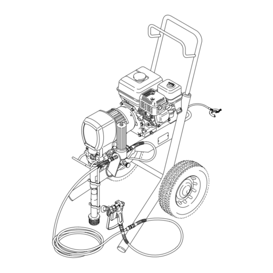
- Page 3 0138 0015 0016 Pressure Control ON/OFF switch 0136 Pressure adjusting knob Air cleaner Fuel Tank Muffler Engine Spark plug cable Fuel shutoff lever Choke Throttle Engine ON/OFF switch Engine oil light Trigger safety latch (shown engaged) Clutch Drive assembly Displacement pump Grounding wire and clamp Fluid filter Pressure drain valve...
-
Page 4: Pressure Relief Procedure
WARNINGS High Pressure Spray Can Cause Serious Injury. For Professional Use Only. Observe All Warnings. Read and understand all instruction manuals before operating equipment. FLUID INJECTION HAZARD General Safety Safety Latch Whenever you stop spraying, even for a moment, always set This equipment generates very high fluid pressure. - Page 5 DO damage. NOT expose Graco hoses to temperatures above 180 F (82 C) or below –40 F (–40 C). All fluid hoses must have strain reliefs on both ends! The strain...
- Page 6 Avertissement La pulvérisation à haute pression peut causer des blessures très graves. Réservé exclusivement à l’usage professionnel. Observer toutes les consignes de sécurité. Bien lire et bien comprendre tous les manuels d’instructions avant d’utiliser le matériel. RISQUES D’INJECTION Consignes générales de sécurité Verrou de sécurité...
-
Page 7: Risques D'incendie Ou D'explosion
RISQUES EN CAS DE MAUVAISE UTILISATION DU MATERIAL Consignes générales de sécurité Tous les tuyaux flexibles doivent avoir des ressorts spirale de Toute utilisation anormale de l’appareil du pulvérisation ou des protection aux 2 bouts! Les spirales de protection contribuent accessoires comme, par exemple, la mise sous une pression à... - Page 8 ADVERTENCIA EL ROCIADO a ALTA PRESIÓN PUEDE CAUSAR GRAVES LESIONES. SOLO PARA USO PROFESIONAL. RESPETE LOS AVISOS DE ADVERTENCIA. Lea y entienda todo el manual de instrucciónes antes de manejar el equipo. PELIGRO DE INYECCION DE FLUIDO Seguridad general Aparatos de seguridad de la pistola pulverizadora Este equipo general un fluido a una presión muy alta.
- Page 9 PELIGRO POR MAL USO DEL EQUIPO Seguridad general Presión del sistema Cualquier mal uso del equipo pulverizador o los accesorios, tal Esta pulverizadora puede desarrollar 210 barías (3000 psi) de como sobre presurización, modificación de piezas, uso de ma- PRESION DE TRABAJO MAXIMA. Asegurar que todo el equi- teriales y productos químicos incompatibles, o utilización de po pulverizador y sus accesorios tienen la capacidad para piezas dañadas o desgastadas, puede hacen que se rompan...
- Page 10 4. Always use the main filter outlet (57) for one gun operation. Never plug this outlet. 3. Fill packing nut/wetcup. (See Fig. 2.) Fill the pack- ing nut/wetcup (416) 1/3 full with Graco Throat Seal Liquid (TSL), supplied. 4. Check the engine oil level. Refer to the Honda en- gine manual, supplied.
- Page 11 Setup 5. Be sure your system is properly grounded be- fore operating it. Read and follow the warning sec- tion, FIRE OR EXPLOSION HAZARD, on page 5. 6. Fill the gas tank. See the Fueling section, below. 0015 7. Flush the pump to remove the lightweight oil which was left in the pump to protect it from rust.
- Page 12 Startup Before you start the sprayer Open the choke as soon as the engine starts, ex- cept in cold weather. In cold weather, leave the 1. See Flushing on page 15 to determine if you should choke closed for 10 to 30 seconds before open- flush the sprayer.
- Page 13 0138 0015 0016 Pressure Control ON/OFF switch 0136 Pressure adjusting knob Air cleaner Fuel Tank Muffler Engine Spark plug cable Fuel shutoff lever Choke Throttle Engine ON/OFF switch Engine oil light Trigger safety latch (shown engaged) Clutch Displacement pump Grounding wire and clamp Fluid filter Pressure drain valve Secondary hose outlet cap...
-
Page 14: Maintenance
Maintenance WARNING CAUTION To reduce the risk of serious injury, including fluid in- For detailed engine maintenance and specifications, jection or splashing in the eyes or on the skin, or injury refer to the separate engine manual, supplied. from moving parts, always follow the Pressure Re- lief Procedure Warning, below, before checking, adjusting, cleaning or shutting down the sprayer. -
Page 15: When To Flush
Flushing When to Flush WARNING To reduce the risk of static sparking and splashing 1. New Sprayer. This unit was factory tested in light- when flushing, always remove the spray tip from the weight oil, which was left in to protect the pump. gun, and hold a metal part of the gun firmly to the side Before using water–base paint, flush with mineral of, and aimed into, a grounded metal pail . -
Page 16: Troubleshooting Guide
Connect cable on top of engine or replace spark plug damaged spark plug. Water frozen in pressure control Return pressure control to authorized Graco dealer for repair. Engine won’t “pull over” Oil seepage into combustion Remove spark plug. Pull starter rope 3 or chamber 4 times. - Page 17 PROBLEM CAUSE SOLUTION Displacement pump output Pump inlet screen clogged Clean. low on upstroke Piston ball check not seating Service piston ball check. See page 31. Piston packings worn or damaged Replace packings. See page 31. Sleeve gasket in displacement Replace.
-
Page 18: Bearing Housing & Connecting Rod
Bearing Housing & Connecting Rod WARNING CAUTION To reduce the risk of serious injury, including fluid in- DO NOT use the bearing housing screw (73) to align jection always follow the Pressure Relief Procedure or seat the bearing housing with the drive housing. Warning on page 14 before checking, adjusting, These parts must be aligned using the locating pins cleaning or shutting off the sprayer. -
Page 19: Drive Housing
Drive Housing WARNING CAUTION To reduce the risk of serious injury, including fluid in- DO NOT drop the gear cluster (18) when removing jection always follow the Pressure Relief Procedure the drive housing (20). The gear cluster is easily dam- Warning on page 14 before checking, adjusting, aged. -
Page 20: Pinion, Clutch, Clamp, Field & Engine
Pinion, Clutch, Clamp, Field & Engine Disassembling these parts can start from the pinion If starting from the pinion housing, first follow Steps 1 to housing, or from the clutch if no pinion service is 6 of Drive Housing, on page 19, and then continue with needed. -
Page 21: Pinion Housing
Pinion Housing Lubricate exterior Press pinion assembly in here Lubricate inner and outer diameters Back of pinion housing (19a) Lubricate teeth **Included in Repair Kit 221–032 CUTAWAY VIEW OF PINION HOUSING (19a) 19m** 19j** 19h** 19g** 19f** 0041 Fig. 9 0169 Repairing the Pinion If purchasing parts separately, use these instructions. - Page 22 Clutch NOTE: The clutch assembly (4) includes the armature 5. The armature (4a) was removed with the pinion (4a) and rotor (4b). The armature and rotor must be re- housing. Remove the armature from the pinion hub. placed together so they wear evenly. 6.
- Page 23 Engine NOTE: The engine must be removed before the Field, Clamp and Clutch Housing can be removed. 1. Working under the mounting plate (A) of the cart, re- move the screw (15), lockwasher (80) and washer (99) which hold the clutch housing (2) to the cart. See Fig.
-
Page 24: Field And Wiring Harness
Field and Wiring Harness NOTE: Refer to Fig. 14. 3. Loosen the four setscrews (12) holding the field (6) to the clutch housing (2). 1. Remove the engine from the cart. See page 23. 4. Pull off the field. 2. Pull the plastic caps (B) off the wire screws (98) in both places on the field. -
Page 25: Clutch Housing
Clamp NOTE: A standard steering wheel puller and two 1/4–28 x 3 or 4 in. long screws are required to remove the clamp. NOTE: Refer to Fig. 15. 1. Loosen the two screws (16) on the clamp (3), work- ing through the slot at the bottom of the clutch hous- ing (2). - Page 26 Reassembly 1. Install the clutch housing (2), capscrews (8) and lockwashers (9) on the engine. See Fig. 17. 2. Install the engine shaft key (13). See Fig. 17. 3. Press the clamp (3) onto the engine shaft. Maintain the 1.99 in. +/– 0.01 (50.55 mm) dimension shown in Fig.
- Page 27 Reassembly 5. Place the engine (1) assembly on the cart. Align the side diameter of the field. The clearance must be at mounting holes. Carefully guide the engine wire (D) least 0.010 in. (0.25 mm) all the way around. Use and wiring harness (96) from the field, through the shim stock or feeler gauge.
-
Page 28: Pressure Control Replacement
Pressure Control Replacement WARNING 2. Working under the engine mounting plate of the cart, disconnect the red, black and white wires. To reduce the risk of serious injury, including fluid in- jection always follow the Pressure Relief Procedure Warning on page 14 before checking, adjusting, For the upright cart, remove the three nuts (61) and cleaning or shutting off the sprayer. - Page 29 Pressure Control Replacement 5. Disconnect the black, red and white wires from the 10. For the upright carts, guide the new pressure control rectifier (307) and switch (302), which are sheathed wires through the wire clamps (97). Fasten the wire- with the conductor (314).
-
Page 30: Pressure Control Adjustment
Pressure Control Adjustment WARNING USE EXTREME CAUTION WHEN PERFORMING THIS CALIBRATION PROCEDURE to reduce the risk of a fluid injection injury or other serious injury, which can result from component rupture, electric shock, fire, explo- sion or moving parts. This procedure sets the sprayer to 2600–3000 psi NEVER EXCEED 3000 psi (210 bar) MAXIMUM (182–210 bar) MAXIMUM WORKING PRESSURE. -
Page 31: Displacement Pump Repair
Removing and Installing the Pump WARNING Installing the pump See Fig. 27. To reduce the risk of serious injury, including fluid in- 1. Screw the pump about 3/4 of the way into the bearing jection always follow the Pressure Relief Procedure housing (21). -
Page 32: Reassembly Procedure
(415*), alternate the packings (412*,406*), and ing the tool, return the sleeve and cylinder to your then male gland (410*) onto the piston valve (422). Graco distributor for removal. See Fig. 30. 7. Remove the sleeve. Screw the large nut (B) of the 2. - Page 33 Displacement Pump Repair Leather Torque nut against rod to Polyethylene 19 ft–lb (26 N.m) Do not allow nut (411) to Lips must face DOWN move when installing piston onto rod Lips must face UP U–cup seal Torque to 110 ft–lb (146 N.m) *409 Fig.
-
Page 34: Parts - Displacement Pump
Parts – Displacement Pump Model 220–872, Series A Includes items 401 to 425 *405 PART NO. DESCRIPTION 401* 107–098 PACKING, o–ring, PTFE *409 403* 108–690 SEAL, u–cup, polyurethane 404* 108–775 BALL; sst 425* 405* 183–171 PLUG 406* 183–174 V–PACKING, leather 407* 407* 183–175... - Page 35 Parts – Complete Sprayers Model 231–052 Sprayer with Upright cart Includes items 201 to 204 Model 231–085 Sprayer with Lo-Boy cart Includes items 202 to 205 Part No. Description 220–886 GM5000 Upright Basic Sprayer See parts list on page 37 223–541 HOSE, grounded, nylon;...
- Page 36 Parts – Basic Sprayer with Upright Cart Detail Model 220–886, Series C Ref 36 Ref 19 Ref 19d Ref 59 77,100 Label See Detail above See page 35 See page 34 Ref 59 0158...
- Page 37 Parts – Basic Sprayer with Upright Cart Model 220–886, Series C Part No. Description Part No. Description 108–802 ENGINE, gasoline 214–570 FLUID FILTER 183–397 HOUSING, clutch See 307–273 for parts 183–517 CLAMP, mounting, rotor 224–775 VALVE, pressure drain 236–568 CLUTCH ASSEMBLY 178–034 TAG, warning Includes items 4a and 4b...
- Page 38 Parts – Basic Sprayer with Lo–Boy Cart Model 222–488, Series A 77,100 Ref 19 Ref 19d Ref 59 Label See page 35 See page 34 0159 Ref 31h...
- Page 39 Parts – Basic Sprayer with Lo–Boy Cart Model 222–488, Series A Part No. Description Part No. Description 108–802 ENGINE, gasoline 222–011 GROUNDING CLAMP & WIRE 183–397 HOUSING, clutch 100–078 SCREW, mach, hex washer hd, No. 8 183–517 CLAMP, mounting, rotor ”...
-
Page 40: Parts - Pressure Control
Parts – Pressure Control Part No. 222–369 – Basic Pressure Control for the GM5000 Sprayers Includes items 300 to 313,315, 325 and 326. Does not includes items 314,316 to 320. For Upright Cart Sprayers , Order the Basic Pressure Control 222–369, and item 314 and/or 316 to 318 as required For Lo–Boy Cart Sprayers, Order the Basic Pressure Control 222–369, and item 314 and/or 319 and 320 as required Part No. - Page 41 Parts – Pressure Control For Upright Cart Sprayers Parts marked with a dagger are supplied with the basic pressure control. 308 ,305 ,306 WHITE RECTIFIER (307) CONNECTIONS GROUND BLACK 315 ,305 0148 0151 For Lo–boy Cart Sprayers Parts marked with a dagger are supplied with the basic pressure control.
- Page 42 160–327 UNION, 90 swivel; 3/4 npt(m x f) 170–705 ADAPTER, intake visibility. 170–706 HOSE, 1” ID x 48”; nylon Order the labels directly from Graco, free of 170–957 TUBE, suction charge. Toll Free: 1–800–328–0211 181–072 STRAINER Apply other...
-
Page 43: Technical Data
Graco Phone Manual Change Number Summary TO PLACE AN ORDER , contact your Graco distrib- utor, or call this number to identify the distributor Added a procedure to set the clearance between rotor closest to you: 1–800–367–4023 Toll Free and the field, on page 27. -
Page 44: The Graco Warranty And Disclaimers
Graco distributor to the original purchaser for use. As purchaser’s sole remedy for breach of this warranty, Graco will, for a period of twelve months from the date of sale, repair or replace any part of the equipment proven defec- tive, with the exception of defects in parts on the drive train/gear box on EM and GM sprayers or power train on EH and GH sprayers, which will be repaired or replaced for twenty-four months from the date of sale for Gas–Hydraulic (GH) and Gas-... -
Page 45: Other Changes
3X7–847 Rev. N Supersedes Rev. L and PCN M Parts Change Notice Some parts in Rev. L of manual 307–847 have changed but have not yet been changed in the instruction manual. Please note the changes below and mark them in your manual or keep this sheet with your manual. - Page 46 1 gun with 0.035 in. tip can safely handle fluids containing HHCs, contact 2 guns with 0.025 in. tip Graco Product Service at 1–800–328–0211. 3 guns with 0.019 in. tip with latex at 2000 psi (138 bar) U.S. patent pending.
- Page 47 7–847 Rev B Supplement to manual 307–847 GM5000 Airless Paint Sprayer WARNING INJECTION HAZARD This is only a quick reference to the features and frequently ordered parts of INSTRUCTIONS this sprayer. To reduce the risk of serious injury, including fluid injection, while erating or repairing this sprayer, follow the warn- ings and instructions in manual 307–847.