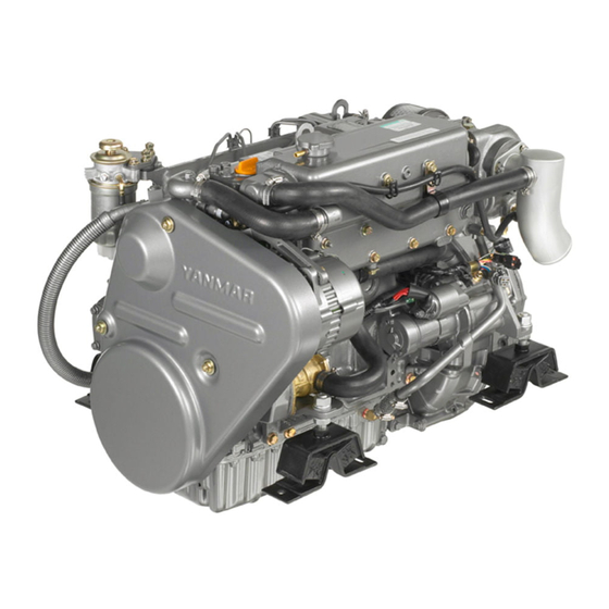
Yanmar 4JH4-TE Operation Manual
Marine diesel engine
Hide thumbs
Also See for 4JH4-TE:
- Service manual (350 pages) ,
- Operation manual (169 pages) ,
- Operation manual (164 pages)
Table of Contents
Advertisement
Advertisement
Table of Contents

Related Manuals for Yanmar 4JH4-TE


Summary of Contents for Yanmar 4JH4-TE
-
Page 3: Table Of Contents
INDEX page No. 1. FOR YOUR SAFETY ........... 1 1.1 Warning Symbols . - Page 4 5.4.3 Inspection and Maintenance ............57 6.
-
Page 5: For Your Safety
1. FOR YOUR SAFETY 1. FOR YOUR SAFETY 1.1 Warning Symbols Most operation, maintenance and inspection problems arise due to users' failure to comply with the rules and precautions for safe operation described in this operation manual. Often, users do not understand or recog- nize the signs of approaching problems. -
Page 6: Safety Precautions
1. FOR YOUR SAFETY 1.2 Safety Precautions (Observe these instructions for your own safety!) 1.2.1 Precautions for Operation Filler Cap of Coolant Tank • Never open the cap of the coolant tank while the engine is still hot. Stem and hot water may spurt out and burn you seriously. Wait until the tempera- ture of the coolant tank has dropped, wrap a cloth around the filler cap and loosen the cap slowly. - Page 7 1. FOR YOUR SAFETY Moving Parts • Do not touch or let your clothing get caught in the moving parts of the engine, such as the front drive shaft, V-belt or propeller shaft, during engine operation. You will be injured. Never operate the engine without covers on the moving parts.
- Page 8 1. FOR YOUR SAFETY Forbidden Modifications • Modification will impair the safety and performance of the product and shorten product life. Also note that any troubles arising from modification are not covered by our warranty. Precautions for Treating Waste • Never dispose of waste oil or other fluid in a field, sewer, river, or the sea. Treat waste matters safely observing regulations or laws.
-
Page 9: Warning Labels
1. FOR YOUR SAFETY 1.3 Warning Labels To insure safe operation, warning device labels have been attached. Their location is shown below and they should always be visible. Please replace if damaged or lost. 4JH4-TE WARNING 128296-07300 008830-00X Product safety labels Part Code No. -
Page 10: Product Explanation
The installation, fitting and surveying of this engine all require specialized knowledge and engineering skills. Consult Yanmar's local subsidiary in your region or your distributor or dealer. This engine is designed for pleasure boat applications. The engine is designed to be operated at: Maximum throttle (3000-3200 rpm) for less than 5% of total engine time. - Page 11 2. PRODUCT EXPLANATION Detail of name plate The nameplate shown below is attached to the engine. Check the engine's model, output, rpm and serial number on the nameplate. Model Gear Model Continuous power kW Speed of prop shaft Fuel stop power kW ENG.No.
-
Page 12: Engine Specifications
2. PRODUCT EXPLANATION 2.2 Engine Specifications Engine model unit 4JH4-TE – Marine gear model ZF30M KM4A2 KMH4A ZF25A SD50-4T Bobtail – Pleasure use – Type Vertical water cooled 4 cycle diesel engine – Combustion system Direct injection – Aspiration Turbocharged –... - Page 13 2. PRODUCT EXPLANATION Engine model unit 4JH4-TE – Marine gear model ZF30M KM4A2 KMH4A ZF25A SD50-4T Bobtail – Type Electric Starting Starting motor V-kW DC 12V - 1.4 kW system Alternator 12V - 80A (12V - 60A optional) 1017 Overall length (36.3)
- Page 14 SD50-4T (coupled – Model ZF30M KM4A2 KMH4A ZF25A at boat builder) – Down angle deg. Applicable engine – 4JH4-TE model Mechanical wet Hydraulic wet Hydraulic wet Mechanical Mechanical – Type multiple disk multiple disk multiple disk cone cone clutch clutch...
-
Page 15: Names Of Parts
2. PRODUCT EXPLANATION 2.3 Names of Parts 4JH4-TE • Operation side 008831-00X Intake silencer Lube oil cooler Fuel priming pump Turbocharger Lube oil filter Dipstick Shift lever Fuel injection pump Intake manifold Marine gear (KMH4A) Fuel filter Oil filler cap •... -
Page 16: Major Servicing Parts
2. PRODUCT EXPLANATION 2.4 Major Servicing Parts Name of part Function Name plate Name plates are provided on the engine and the marine gear and have the model serial number and other data. Fuel filter Removes dust and water from fuel. The filter is a cartridge type, and the inner element should be replaced before clogging occurs. -
Page 17: Control Equipment
2. PRODUCT EXPLANATION 2.5 Control Equipment The equipment in the control room, making remote control possible, consists of the instrument panel, which is connected to the engine by wire harness, and the remote control handle, which is hooked up by remote con- trol cables to the engine control lever and marine gear. - Page 18 2. PRODUCT EXPLANATION Instruments, equipment Functions Key switch The switch key can be inserted or removed. Rotary switch with 4 positions All electric current is cut off. The electric current to the controls and equipment is turned on. Engine keeps running. To stop the engine, the key switch should be in the ON position.
-
Page 19: Alarm Equipment (Lamps/Buzzer)
2. PRODUCT EXPLANATION (3) Alarm Equipment (Lamps and Buzzer) When the sensor detects a problem during operation, the lamp comes on and the buzzer sounds. Alarm lamps are located on the panel, buzzer is located on the back of panel. Under normal conditions, the monitors are off. -
Page 20: Single Lever Remote Control Handle
When turning the knob clockwise, the handle is fixed. When loosening the knob, the handle can be moved. (Only engine speed control) Yanmar recommends the use of a single-lever type 008441-00E for the remote control system. If only the two-lever... -
Page 21: Shut-Down Equipment
2. PRODUCT EXPLANATION 2.5.3 Shut-down Equipment Electric operation Push the stop button on the instrument panel when the key is in the ON position. If the engine is stopped suddenly during operation, the temperature of various engine parts will increase and engine troubles may occur. -
Page 22: Before Operation
3. BEFORE OPERATION 3. BEFORE OPERATION 3.1 Fuel Oil, Lube Oil and Cooling Water 3.1.1 Fuel Oil When other than the specified fuel oil is used, the engine will not perform to full capacity and parts may be damaged. IMPORTANT: Only use the recommended fuel to obtain the best engine performance and to keep the durability of the engine, also to comply with the emission regulations. - Page 23 3. BEFORE OPERATION (2) Handling of Fuel Oil 1) Water and dust in the fuel cause engine failure. When fuel is stored, be sure that the inside of the storage container is clean, and that the fuel is stored away from dirt or rain water. 2) Keep the fuel container stationery for several hours to allow any dirt or water to settle to the bot- tom.
-
Page 24: Lube Oil
Atmospheric temperature 008408-00E (3) Selection of Oil for Sail Drive Unit ® Only QuickSilver High Performance Gear Lube must be selected and used for SD50-4T of 4JH4-TE. ® QuickSilver is registered trademark of Brunswick Corporation. (4) Handling the Lube Oil 1) When handling and storing lube oil, be careful not to allow dust and water to enter the lube oil. -
Page 25: Cooling Fresh Water
Handling of Coolant 1) Choose antifreeze, which will not have any Consult your Yanmar dealer or distributor on the adverse effects on the materials (cast iron, alumi- use of coolant/antifreeze, and detergents. num, copper, etc.) of the engine's fresh water Coolant/antifreeze, which provides good perfor- cooling system. -
Page 26: Before Initial Operation
3. BEFORE OPERATION 3.2 Before Initial Operation Perform the following before using the engine for the first time: 3.2.1 Supply Fuel Oil Using gasoline, etc. may cause a fire. To avoid mistakes, be sure to double-check the kind of fuel before filling. Wipe off any spilled fuel carefully. -
Page 27: Supply Marine Gear Lube Oil
3. BEFORE OPERATION 3.2.3 Supply Marine Gear Lube Oil 1) Remove the filler port cap at the top of the hous- KMH4A ing, and fill with marine gear lube oil. 2) Fill with oil to the upper limit on the dipstick, insert the dipstick fully to check the level. -
Page 28: Supply Cooling Fresh Water
3. BEFORE OPERATION 3.2.4 Supply Cooling Fresh Water Supply cooling fresh water according to the following 4JH4-TE procedures. Be sure to add antifreeze to the cooling fresh water. 1) Be sure to close all the water drain cocks. Drain cocks in... - Page 29 3. BEFORE OPERATION 2) Remove the filler cap of the fresh water cooler by turning the cap counterclockwise 1/3 of a turn. 3) Pour cooling water slowly into the fresh water/cool- ant tank so that air bubbles do not develop. Pour until the water overflows from the filler port.
-
Page 30: Cranking
3. BEFORE OPERATION 3.2.5 Cranking When the engine has not been used for a long period of time, all of the moving parts will be lack of lube oil. Using the engine in this condition will lead to seizure. After a long period of disuse, distribute lube oil to each part by cranking before warm-up operation. -
Page 31: Check And Resupply Lube Oil And Cooling Water
3. BEFORE OPERATION 3.2.6 Check and Resupply Lube Oil and Cooling Water When engine oil, clutch oil, or cooling water is supplied for the first time or when they must be replaced, con- duct a trial operation of the engine for about 5 minutes and check the quantity of lube oil and cooling water. The trial engine operation will send the lube oil and cooling water to the passages, so the lube oil and cooling water levels will drop. -
Page 32: How To Operate
4. HOW TO OPERATE 4. HOW TO OPERATE Alcohol • Never operate the engine while you are under the influence of alcohol or when you are ill or feel unwell as this results in accidents. To prevent exhaust gas poisoning, ensure good ventilation during operation. Install ventilation windows, ports or ventilators in the engine room. -
Page 33: Inspection Before Starting
If the coolant runs out too often, or only the coolant in the fresh water tank drops without any change in the water level of the coolant recovery tank, there may be some leakage of water or air. In such cases, consult your Yanmar dealer or distributor without delay. - Page 34 4. HOW TO OPERATE Note: The water rises in the coolant recovery tank during engine operation. This is not abnormal. After stopping the engine, the cooling water cools down and the extra water in the coolant recovery tank returns to the coolant tank.
-
Page 35: How To Start The Engine
4. HOW TO OPERATE 4.2 How to Start the Engine (1) Start the Engine According to the Following Procedures: 1) Open the seacock. 2) Open the fuel cock. 3) Set the remote control lever in NEUTRAL. Safety equipment should make it impossible to start the engine in any other position than NEUTRAL. - Page 36 4. HOW TO OPERATE (2) Restarting after Starting Failure Before turning the key switch again, be sure to con- firm that the engine has stopped completely. If an attempt to restart is made while the engine has not stopped, the pinion gear of the starter motor will be damaged.
- Page 37 4. HOW TO OPERATE (4) After the Engine has Started After the engine has started, check the following items at a low engine speed: 1) Check that the gauges and alarm devices on the instrument panel are normal. 2) Check for water or oil leakage from the engine. 3) Check that exhaust color, engine vibrations and sound are normal.
-
Page 38: Remote Control Handle Operation
4. HOW TO OPERATE 4.3 Remote Control Handle Operation (1) Engine Acceleration and Deceleration Use the throttle handle to control acceleration and deceleration. Move the handle slowly. (2) FORWARD - NEUTRAL (Boat Stopped) - REVERSE Clutch Use the clutch handle to change from FORWARD to NEUTRAL (boat stopped) or to REVERSE. - Page 39 4. HOW TO OPERATE (3) Switching to Trawling (Available for KMH4A only) OPTION KMH4A Use the trawling handle to begin trawling. When changing from forward or reverse operation to trawl- ing, the speed of propeller revolution will be reduced to a bare minimum. When trawling, do not raise the engine speed over 1000min as this results in early wear of and dam-...
-
Page 40: Cautions During Operation
4. HOW TO OPERATE 4.4 Cautions During Operation Always be on the lookout for problems during engine operation. Pay particular attention to the following: (1) Is sufficient water being discharged from the seawater outlet pipe? If the discharge is small, stop the engine immediately; identify the cause and repair. (2) Is the exhaust color normal? The continuous emission of black exhaust smoke indicates engine overloading. -
Page 41: Shut-Down The Engine
4. HOW TO OPERATE 4.5 Shut-down the Engine Stop the engine in accordance with the following pro- cedures: 1) Stop the boat. Reduce the engine speed to the low idle speed and put the remote control handle in NEUTRAL 2) Be sure to race the engine before shut-down. (See 4.4 (7)) 3) Cool down the engine at low speed (approximately 1000 min... -
Page 42: Long Term Storage
1 Coolant tank 1) Open the seawater drain cock attached on the seawater pump cover seawater pump cover for 4JH4-TE. Open the sea- 2 Fresh water pump 4 Drain cocks for fresh water water drain cocks attached on the seawater pump cover and inter cooler for 4JH4-HTE. - Page 43 4. HOW TO OPERATE (2) Be sure to add antifreeze to the cooling fresh water. If antifreeze is not used, the cooling fresh water may freeze and damage parts of the cooling water system (fresh water cooler, cylinder block, cylinder head, etc.) when ambient temperature is below 0° [32°F]. Also if antifreeze is not used, the cooling water system (fresh water cooler, cylinder block, cylinder head, etc.) will rust during long term storage.
-
Page 44: Maintenance & Inspection
Conduct periodic inspections according to the procedures described in this Operation Manual. Use Genuine Yanmar Parts. Be sure to use genuine Yanmar parts for consumable and replacement parts. Use of other parts will reduce engine performance and shorten the life of the engine. -
Page 45: List Of Periodic Inspection Items
Neglect of periodic inspection may lead to engine troubles and shorten the life of the engine. Inspection and servicing at 1000 hours and thereafter require special knowledge and techniques. Consult your Yanmar dealer or distributor. : Check : Replace... - Page 46 5. MAINTENANCE & INSPECTION : Check : Replace : Consult local dealer Every Every Every Every Before Initial System Item 50 hrs. or 250 hrs. or 500 hrs. or 1000 hrs. or starting 50 hrs. monthly** 1 year** 2 years** 4 years** Wash turbocharger blower Air intake...
-
Page 47: Periodic Inspection Items
5. MAINTENANCE & INSPECTION 5.3 Periodic Inspection Items 5.3.1 Inspection on Initial 50 Hrs. of Operation (or after 1 Month) (1) Replacing the Engine Lube Oil and Lube Oil Filter (1st time) During initial operation of the engine, the oil is quickly contaminated due to the initial wear of internal parts. - Page 48 During initial operation of the engine, the intake/ exhaust valve clearance may be quickly changed due to the initial wear of internal parts. Therefore adjust- ment is necessary. This adjustment requires special- ized knowledge and techniques. Consult your Yanmar dealer or distributor.
- Page 49 5. MAINTENANCE & INSPECTION (5) Adjusting the Remote Control Cable The various control levers on the engine side are connected to the remote control lever by remote con- trol cables. The cables will become stretched and the attachments loose after long hours of use causing deviation.
- Page 50 5. MAINTENANCE & INSPECTION 3) Adjusting the position of the trawling remote con- trol handle KMH4A a) Check to see that the trawling lever on the marine gear side is in the high speed position when the trawling remote control handle is in H (high speed) position.
- Page 51 The flexible engine mounts are compressed a little in the initial engine operation and it may cause the cen- tering misalignment between the engine & the propel- ler shaft. This adjustment requires specialized knowledge and techniques. Consult your Yanmar dealer or distribu- tor.
-
Page 52: Inspection Every 50 Hrs. (Or Monthly)
5. MAINTENANCE & INSPECTION 5.3.2 Inspection Every 50 Hrs. (or Monthly) (1) Drain the Fuel Filter When water and dirt are mixed in with the fuel, it becomes impossible for the fuel injection pump and the fuel injection valve to work. Drain periodically to keep the filter from becoming clogged. - Page 53 If the power is also used for onboard lighting or other purposes, the generating and charging capacities may be insufficient. In such cases, consult your Yanmar dealer or distributor.
-
Page 54: Inspection Every 250 Hrs
5. MAINTENANCE & INSPECTION 5.3.3 Inspection Every 250 Hrs. (1) Draining the Fuel Tank Refer to 5.3.1 (3). (2) Replacing the Fuel Filter Replace the fuel filter periodically before there is clogging and the fuel flow is reduced. 1) Close the fuel cock of the fuel tank. 2) Drain the fuel from the fuel drain cock at the bot- tom of the fuel filter. -
Page 55: Checking Impeller Of Seawater Pump
5. MAINTENANCE & INSPECTION (5) Checking the Impeller of Seawater Pump Depending on the use, the inside parts of the seawa- ter pump deteriorate and the seawater discharge per- formance drops. At the specified interval or when the volume of discharged seawater is reduced, inspect the seawater pump in accordance with the following procedures;... -
Page 56: Washing Turbocharger Blower
(6) Washing Turbocharger Blower When engine speed seems sluggish or the exhaust color poor, the blades of the turbocharger blower may be dirty. Wash the blower. Consult your Yanmar dealer or distributor. (7) Cleaning Exhaust/Water Mixing Elbow The mixing elbow is attached to the turbocharger. -
Page 57: Inspection Every 500 Hrs
Reassemble after it is completely dry. (9) Checking Wiring Connectors Check whether each electric connection part doesn't have looseness. If the disconnection part will be found, repair or consult with Yanmar distributor or dealer. (10) Retightening All Major Nuts and Bolts When operating for long periods of time, The major bolts and nuts may come loose. -
Page 58: Inspection Every 1000 Hrs
If a large amount of water leaks continuously from the water drain pipe beneath the seawater pump during operation, disassembly and maintenance (replacement of the lip seal) is necessary. When disassembly and maintenance of the seawater pump is necessary, consult your Yanmar dealer or dis- tributor. -
Page 59: Annually
Be sure to replace the Yanmar flexible engine mounts every 1000 hours or 4 years, whichever comes first. This maintenance requires specialized knowledge. Consult your Yanmar dealer or distributor. -
Page 60: Epa Requirements
This regulation is applied only in U.S.A. 5.4.1 EPA Certification Plate This engine has the following EPA certification plate attached: • EPA certification plate (4JH4-TE) MARINE ENGINE EMISSION CONTROL INFORMATION THIS ENGINE COMPLIES TO U.S.EPA REGULATIONS 40 CFR PART 94 WHICH APPLY TO MARINE ENGINES... -
Page 61: Conditions To Insure Compliance With Emission Standards
Check fuel injection nozzle (cleaning) 1500 hours Check fuel injection nozzle 3000 hours (adjustment) Check fuel injection pump (adjustment) 3000 hours Check turbocharger (adjustment) 3000 hours Note: The inspection and maintenance shown above are to be performed at your Yanmar dealer or distributor. -
Page 62: Trouble And Troubleshooting
6. TROUBLE AND TROUBLESHOOTING 6. TROUBLE AND TROUBLESHOOTING Trouble Probable cause Measure Reference Alarm buzzer and alarm lamps on during opera- tion. Shift to low speed operation immediately, and check which lamp has come on. Stop the en- gine for inspection. If no abnormality is identified and there is no problem with operation, re- turn to port at your lowest speed and request repairs. - Page 63 Lube oil burns; excessive consumption. Ask for repairs. Consulting your Yanmar dealer or distributor Refer difficult problems and repairs to your Yanmar dealer or distributor. At the time of trouble, check and report the following: 1. Engine model and serial number: 2.
-
Page 64: System Diagrams
7. SYSTEM DIAGRAMS 7. SYSTEM DIAGRAMS 7.1 Piping Diagrams Fuel overflow Marks of piping Fuel oil inlet Rubber hose Fuel oil filter (Cartridge type) Steel pipe Pressure control valve Lube oil pump C1201T Copper pipe Fresh water temperature sensor (Option) Screw joint (Union) Hot water connection return Cooling water pump (Fresh water) - Page 65 008430-00E...
- Page 66 008431-00E...
-
Page 67: Wiring Diagrams
7. SYSTEM DIAGRAMS 7.2 Wiring Diagrams Option (Color coding) Engine harness Alarm lamps Buzzer Black Oil pressure White Ignition CWF temperature Blue Air heater/grow (option) Sail drive seal Charge Red/Black Alternator exciter Fuse (3A) Blue/Black Alternator charge alarm Stop switch Yellow/White Engine oil pressure alarm Diodes... - Page 68 Allowable length by cross sectional area of battery cable section of cable Allowable length L=1+2+3(m) 15(mm < 0.86(m) 20(mm < 1.3(m) 30(mm < 2.3(m) 40(mm < 2.8(m) 50(mm < 3.5(m) 60(mm < 4.1(m) Key switch 30 AC G1 G2 17 GLOW WG B YB GB...
- Page 69 Allowable length by cross sectional area of battery cable section of cable Allowable length L=1+2+3(m) 15(mm < 0.86(m) 20(mm < 1.3(m) 30(mm < 2.3(m) 40(mm < 2.8(m) 50(mm < 3.5(m) 60(mm < 4.1(m) 34 35 Key switch 30 AC G1 G2 17 GLOW WG B...