Table of Contents
Advertisement
QQ
3 7 63 1515 0
TE
L 13942296513
Black color : MPP model
Yellow color : MDT, MGT models
www
.
http://www.xiaoyu163.com
SERVICE MANUAL
SERVICE MANUAL
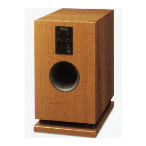
SUB WOOFER SYSTEM
SL-105 / HTP-2
SL-105
POWERED SUBWOOFER
MPP
230-240V AC, 50Hz
MDT
120V AC, 60Hz
MGT
220-230V AC, 50/60Hz
SAFETY-RELATED COMPONENT
WARNING!!
COMPONENTS IDENTIFIED BY MARK
Schematic Diagram AND IN THE PARTS LIST ARE
CRITICAL FOR RISK OF FIRE AND ELECTRIC SHOCK.
REPLACE THESE COMPONENTS WITH ONKYO
PARTS WHOSE PART NUMBERS APPEAR AS SHOWN
IN THIS MANUAL.
MAKE LEAKAGE-CURRENT OR RESISTANCE
MEASUREMENTS TO DETERMINE THAT EXPOSED
PARTS ARE ACCEPTABLY INSULATED FROM THE
SUPPLY CIRCUIT BEFORE RETURNING THE
x
ao
u163
y
APPLIANCE TO THE CUSTOMER.
i
http://www.xiaoyu163.com
2 9
8
D-L5 x 5
SATELLITE SPEAKERS
Q Q
3
6 7
1 3
1 5
ON THE
co
.
9 4
2 8
Ref. No.3709
0 5
8
2 9
9 4
2 8
m
SL-105
9 9
082001
9 9
Advertisement
Table of Contents

Related Manuals for Onkyo SL-105


Summary of Contents for Onkyo SL-105
- Page 1 COMPONENTS IDENTIFIED BY MARK ON THE SCHEMATIC DIAGRAM AND IN THE PARTS LIST ARE CRITICAL FOR RISK OF FIRE AND ELECTRIC SHOCK. REPLACE THESE COMPONENTS WITH ONKYO PARTS WHOSE PART NUMBERS APPEAR AS SHOWN IN THIS MANUAL. MAKE LEAKAGE-CURRENT OR RESISTANCE...
- Page 2 SL-105 3 7 63 1515 0 SERVICE NOTE 1. Replacing the fuses This symbol located near the fuses indicates that the fuse used is fast operating type. For continued protection against fire hazard, re- place with same type fuse. For fuse rating refer to the marking adja- cent to the symbol.
- Page 3 (or receiver) over a period of a few minutes, You can select any frequency between 50 Hz and 200 the SL-105 automatically enters the standby state. If a Hz depending on the characteristics of the speaker constant level signal is later received from the amplifier system being used with the SL-105.
- Page 4 SL-105 3 7 63 1515 0 EXPLODED VIEW (CABINET SECTION) Indicated in the exploded view of an amplifier section. E901 P535 L 13942296513 u163 http://www.xiaoyu163.com...
- Page 5 SL-105 3 7 63 1515 0 CHASSIS EXPLODED VIEW (AMPLIFIER SECTION) L 13942296513 Q951 Q516 Q541 Q952 Q515 Q516B R602 Q515A T901 E811 F901 P901 u163 http://www.xiaoyu163.com...
- Page 6 SL-105 3 7 63 1515 0 EXPLODED VIEW PARTS LIST NOTE: THE COMPONENTS IDENTIFIED BY MARK ARE CRITICAL FOR RISK OF FIRE AND <AMPLIFIER ASSEMBLY PARTS LIST> ELECTRIC SHOCK. REPLACE ONLY WITH REF. NO. PART NO. DESCRIPTION PART NUMBER SPECIFIED.
- Page 7 SL-105 3 7 6 3 1 5 1 5 0 BLOCK DIAGRAM S P E A K E R N A E T C - 6 8 7 0 - 3 N A A F - 6 8 6 6 - 3...
- Page 8 SL-105 3 7 63 1515 0 SCHEMATIC DIAGRAM N A E T C - 6 8 7 0 - 3 N A A F - 6 8 6 6 - 3 R 3 1 8 1 8 K C 3 0 6...
- Page 9 SL-105 3 7 63 1515 0 N O T E A R E C R I T I C A L F O R S A F E T Y . T H E C O M P O N E N T S I D E N T F I E D M A R K R E P L A C E O N L Y W I T H P A R T N U M B E R S P E C I F I E D .
- Page 10 SL-105 3 7 6 3 1 5 1 5 0 SCHEMATIC DIAGRAM N O T E M A R K A R E C R I T I C A L F O R S A F E T Y .
- Page 11 SL-105 3 7 63 1515 0 PRINTED CIRCUIT BOARD PARTS LIST 1/2 U1: Main circuit PC board assy, NAAF-6865-3B/3C/3D REF. NO. PART NO. DESCRIPTION REF. NO. PART NO. DESCRIPTION Resistors R505,R506 415421023 1k ohm,+/-2%,1/4W, Carbon Q624 22240369 M5218AP R508,R951,...
- Page 12 SL-105 3 7 63 1515 0 PRINTED CIRCUIT BOARD VIEWS U1: Main circuit PC board NAAF-6865 Q541 Q952 R602 Q951 Q516 Q515 J544 J513 J525 J543 J519 J533 R951 R952 R531 R953 R954 R532 J526 R534 D951 D952 R533...
- Page 13 SL-105 3 7 63 1515 0 PRINTED CIRCUIT BOARD VIEWS U2:Input terminal PC board NAAF-6866 Component side view NCAF-6866 25136866 JL303A JL953B J306 Q301 Q302 Q301 Q302 P301 P302 S301 P301 P302 U5: Power transformer PC board NAPS-6869 U8: Power indicator...
- Page 14 SL-105 3 7 63 1515 0 ADJUSTMENT PROCEDURES AND SETTING POSITION 1 Adjustment of idling current a. Set the voltage at P531 to 0.25mV by adjusting R544 under the condition of no input and no load. (Auto standby switch is off position.) b.
- Page 15 SL-105 3 7 63 1515 0 PACKING VIEW Cellophane tape L 13942296513 Cellophane tape PACKING PARTS LIST REF. NO PART NO. DESCRIPTION REF. NO PART NO. DESCRIPTION 62-000-394-01 RCA PIN cord 80-000-472-01 Pad (Top) 65-000-204-01 Foot 80-000-472-11 Pad (Bottom)
- Page 16 HTP-2 3 7 63 1515 0 PACKING VIEW HTP-2 (SL-105 + D-L5) D-L5 Cellophane tape REF. NO PART NO. DESCRIPTION 80-000-472-01 Pad (Top) 80-000-472-11 Pad (Bottom) 85-000-376-71 Poly bag 85-000-400-21 Sheet L 13942296513 62-000-402-11 Speaker cord 2 sets 62-000-402-01...
- Page 17 Tel: 072-831-8111 Fax: 072-833-5222 ONKYO EUROPE ELECTRONICS GmbH Industriestrasse 20, 82110 Germering, GERMANY Tel: 089-849-320 Fax: 089-849-3265 E-mail: info@onkyo.de ONKYO CHINA LIMITED Units 2102-2107, Metroplaza Tower I, 223 Hing Fong Road, Kwai Chung, N.T., HONG KONG Tel: 852-2429-3118 Fax: 852-2428-9039...
- Page 18 SL-105 3 7 63 1515 0 PRINTED CIR$CUIT BOARD PARTS LIST 2/2 U5: Power transformer PC board assy, NAPS-6869-3B/3C/3D REF. NO. PART NO. DESCRIPTION N NOTE: THE COMPONENTS IDENTIFIED BY MARK Socket AS ARE CRITICAL FOR RISK OF FIRE AND...
- Page 19 SL-105 3 7 63 1515 0 EXPLODED VIEW PARTS LIST REF. NO. PART NO. DESCRIPTION 1W204565-3B <MPP> Main circuit PC board assy, NAAF-6865-3B 1W204565-3C <MDT> Main circuit PC board assy, NAAF-6865-3C 1W204565-3D <MGT> Main circuit PC board assy, NAAF-6865-3D 1W204566-3B <MPP>...