Table of Contents
Advertisement
Available languages
Available languages
Quick Links
© 2006 Victor Company of Japan, Limited
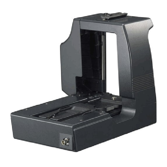
STUDIO ADAPTER
STUDIOADAPTER
APTATEUR DE STUDIO
ADAPTADOR DE ESTUDIO
ADATTATORE STUDIO
KA-HD250
For Customer Use:
Enter below the Serial No. which is located on the body.
Retain this information for future reference.
Model No.
Serial No.
LST0445-001B
BEDIENUNGSANLEITUNG
KA-HD250
INSTRUCTIONS
INSTRUCTIONS
INSTRUCCIONES
ISTRUZIONI
LST0445-001B
Advertisement
Chapters
Table of Contents

Related Manuals for JVC KA-HD250


Summary of Contents for JVC KA-HD250
- Page 1 © 2006 Victor Company of Japan, Limited STUDIO ADAPTER STUDIOADAPTER APTATEUR DE STUDIO ADAPTADOR DE ESTUDIO ADATTATORE STUDIO KA-HD250 For Customer Use: Enter below the Serial No. which is located on the body. Retain this information for future reference. Model No. KA-HD250 Serial No.
- Page 2 Operation of this equipment in a residential area is likely to cause harmful interference in which case the user will be required to correct the interference at his own expense. CAUTION: CHANGES OR MODIFICATIONS NOT APPROVED BY JVC COULD VOID USER’S AUTHORITY TO OPERATE THE EQUIPMENT. NOTE: The rating plate (serial number plate) is on this unit.
-
Page 3: Table Of Contents
Cable Length (Business users) Exclusive Cable 10 meters If you wish to dispose of this product, please visit our web page www.jvc-europe.com to obtain information about the PROMPTER OUTPUT Coaxial Cable 5 meters take-back of the product. DC INPUT Exclusive Cable... -
Page 4: Operating Precautions
CAUTION : Points to pay attention to during operation. MEMO Notation used in this manual • The copyright for this manual is property of JVC. Unau- thorized reproduction or publication of this manual in part or in whole is strictly forbidden. -
Page 5: Rear Section
VF OUTPUT VF OUTPUT terminal terminal Headset (BNC × 3) (Round 20-Pin) DT109 (Beyerdynamic) INTERCOM terminal STUDIO KIT KA-HD250 DC cable AC Power Adapter IA-60a, VL-2PLUS (IDX) DC INPUT terminal RM terminal REMOTE cable Tripod REMOTE CONTROL UNIT RM-P210 TALLY... -
Page 6: Installation
PREPARATIONS While pushing the safety lever, pull the lock lever toward Installation the front until the front mount clip clicks into place. Mounting on a Tripod Use the screw holes on the bottom to mount on a tripod. There are multiple screw holes. Use well-balanced holes to mount to a tripod. -
Page 7: Output Signals When The Viewfinder Is Connected
PREPARATIONS Connecting to Remote Output signals when the viewfinder is connected Control Unit RM-P210 VF OUTPUT signals and displays are as shown below. VF-P400 Connection Termi- (Round (BNC×3) (BNC×3) (BNC×3) (BNC×3) (BNC×1) Switch off RM-P210 power supply before attempting the con- 20p) nection. -
Page 8: Notes On Operating Rm-P210
PREPARATIONS Notes on Operating RM- GAMMA P210 DNR LEVEL Some actions are not compatible when setting the GY- HD250 with RM-P210 menu operations. (G: Action available ×: No action) Function Action DTL FRQ DETAIL (CONTOUR) SKIN DTL IRIS MANU AUTO COLOR MATRIX WHITE BAL MANU... - Page 9 STUDIOADAPTER KA-HD250 BEDIENUNGSANLEITUNG...
-
Page 10: Besondere Merkmale
(EMV) (z. B. speziell gebautes Sende- oder Aufnahmestudio) und Wenn Sie dieses Produkt entsorgen möchten, besuchen Sie im Freien ländlicher Umgebungen. bitte unsere Webseite www.jvc-europe.com, um Informatio- Um eine optimale Leistung sowie eine elektromagnetische Kompati- nen zur Rücknahme des Produkts zu erhalten. -
Page 11: Vorsichtsmaßnahmen Für Die Bedienung
Signale verfügbar. ACHTUNG: Weist darauf hin, dass hier besonders auf- MEMO In diesem Handbuch verwendete Schreibweise • JVC besitzt das Urheberrecht für dieses Handbuch. Eine unbefugte Vervielfältigung oder Veröffentlichung dieses Handbuchs, auch auszugsweise, ist strengstens untersagt. • Alle in diesem Dokument aufgeführten Produktnamen sind Marken oder eingetragene Marken der jeweiligen Unternehmen. -
Page 12: Rückseite
DM-3106 (Astrodesign) VF-P400 Umwandlungsstecker VF OUTPUT VF OUTPUT Anschlussbuchse Anschlussbuchse Headset (3× BNC) (rund, 20-polig) DT109 (Beyerdynamic) INTERCOM-Anschluss STUDIO KIT KA-HD250 Gleichstromkabel Netzadapter IA-60a, VL-2PLUS (IDX) Gleichstromeingang DC INPUT RM-Anschluss Fernsteuerkabel Stativ REMOTE CONTROL UNIT RM-P210 TALLY CALL FULL AUTO... -
Page 13: Installation
VORBEREITUNGEN Halten Sie den Sicherheitshebel gedrückt, und ziehen Installation Sie den Verriegelungshebel nach vorn, bis die vordere Befestigungsklemme einrastet. Anbringen an einem Stativ Zum Anbringen an einem Stativ verwenden Sie die Befesti- gungslöcher an der Unterseite. Es sind mehrere Befestigungslöcher vorhanden. Für die Montage auf einem Stativ verwenden Sie die Löcher, die die Kamera am besten ausbalancieren. -
Page 14: Ausgegebene Signale Bei Anschluss Des Suchers
VORBEREITUNGEN Anschließen an die Fern- Ausgegebene Signale bei Anschluss des Suchers steuereinheit RM-P210 Die Signale und Anzeigen von VF OUTPUT können Sie der untenstehenden Tabelle entnehmen. Anschlussverbindung VF-P400 Schalten Sie zuerst die Stromversorgung des RM-P210 aus, schluss- (Round (BNC×3) (BNC×3) (BNC×3) (BNC×3) (BNC×1) -
Page 15: Hinweise Zum Bedienen Des Rm-P210
VORBEREITUNGEN Hinweise zum Bedienen GAMMA des RM-P210 DNR LEVEL Einige Aktionen sind nicht kompatibel, wenn der GY-HD250 über Menübefehle des RM-P210 bedient wird. (G: Aktion verfügbar ×: Keine Aktion) Funktion Aktion DTL FRQ DETAIL (CONTOUR) SKIN DTL IRIS MANU AUTO COLOR MATRIX WHITE BAL MANU... - Page 16 ADAPTATEUR DE STUDIO KA-HD250 INSTRUCTIONS...
-
Page 17: Fonctions Principales
à la législation nationale. Port Câble Longueur (Utilisateurs professionnels) Câble exclusif 10 mètres Si vous souhaitez éliminer ce produit, visitez notre page Web www.jvc-europe.com afin d’obtenir des informations sur sa PROMPTER OUTPUT Câble coaxial 5 mètres récupération. DC INPUT Câble exclusif 5 mètres TALLY OUTPUT Câble exclusif... -
Page 18: Précautions De Fonctionnement
ATTENTION : Points auxquels prêter attention pendant RAPPEL Notation utilisée dans ce manuel • Le copyright de ce manuel est la propriété de JVC. Toute reproduction ou publication non autorisée de ce manuel en tout ou en partie est strictement interdite. -
Page 19: Section Arrière
Prise VF OUTPUT VF OUTPUT Casque (BNC × 3) (ronde à 20 broches) DT109 (Beyerdynamic) Prise INTERCOM STUDIO KIT KA-HD250 Câble CC Adaptateur secteur IA-60a, VL-2PLUS (IDX) Prise DC INPUT Prise RM Câble REMOTE Trépied REMOTE CONTROL UNIT RM-P210 TALLY... -
Page 20: Installation
PRÉPARATIFS Tout en poussant sur le levier de sécurité, tirez le levier Installation de verrouillage vers l’avant jusqu’à ce que la fixation avant se bloque en position. Fixation sur un trépied Utilisez les orifices de vis situés au bas pour fixer sur un tré- pied. -
Page 21: Signaux De Sortie Lors De La Connexion Au Viseur
PRÉPARATIFS Connexion à la télécom- Signaux de sortie lors de la con- nexion au viseur mande RM-P210 Les signaux VF OUTPUT et les écrans d’affichage sont indi- qués ci-dessous. VF-P400 Connexion Coupez l’alimentation de la télécommande RM-P210 avant (ronde à Prise de tenter la connexion. -
Page 22: Remarques Relatives Au Fonctionnement De La Télécommande Rm-P210
PRÉPARATIFS Remarques relatives au fonctionne- GAMMA ment de la télécommande RM-P210 Certaines actions sont incompatibles lorsque vous réglez la DNR LEVEL caméra GY-HD250 avec des opérations de menu de la télé- commande RM-P210. (G : Action disponible × : Aucune action) Fonction Action DTL FRQ... - Page 23 ADAPTADOR DE ESTUDIO KA-HD250 INSTRUCCIONES...
-
Page 24: Características Principales
Si desea desechar este producto, visite nuestra página Web compatibilidad electromagnética, se recomienda utilizar cables que www.jvc-europe.com para obtener información acerca de la no excedan las siguientes longitudes: retirada del producto. Puerto Cable Longitud [Otros países no pertenecientes a la Unión Europea]... -
Page 25: Precauciones De Funcionamiento
ADVERTENCIA : indica que se debe prestar atención NOTA Anotaciones utilizadas en este manual • El copyright de este manual es propiedad de JVC. La reproducción o publicación total o parcial no autorizada de este manual está estrictamente prohibida. • Todos los nombres de productos que aparecen en este documento son marcas comerciales o registradas de sus respectivas empresas. -
Page 26: Sección Trasera
INTRODUCCIÓN k[CALL] Botón CALL /Indicador de alimentación Controles, indicadores y conectores Se ilumina en verde cuando se enciende el adaptador de estudio. (continuación) Sin embargo, se ilumina en ámbar cuando la cámara está apagada. Pulse para enviar una señal de llamada al operador del mando a distancia si no se están utilizando los auriculares del intercomunicador. -
Page 27: Instalación
PREPARATIVOS Mientras empuja la palanca de seguridad, tire de la Instalación palanca de bloqueo hacia adelante hasta que la brida del montaje delantero quede encajada. Instalación en un trípode Utilice los orificios de rosca de la parte inferior para montar un trípode. -
Page 28: Señales De Salida Cuando El Visor Está Conectado
PREPARATIVOS Conexión al mando a Señales de salida cuando el visor está conectado distancia RM-P210 Las visualizaciones y señales VF OUTPUT son las que se muestran a continuación. Conexión VF-P400 Apague la alimentación del RM-P210 antes de intentar la Termi- (Alrede- conexión. -
Page 29: Notas Sobre El Funcionamiento Del Rm-P210
PREPARATIVOS Notas sobre el funcionamiento GAMMA del RM-P210 DNR LEVEL Algunas acciones no son compatibles cuando se ajusta la GY-HD250 con las funciones de menú del RM-P210 (G: acción disponible ×: acción no disponible) Función Acción DTL FRQ DETAIL (CONTOUR) SKIN DTL IRIS MANU... - Page 30 ADATTATORE STUDIO KA-HD250 ISTRUZIONI...
-
Page 31: Caratteristiche Principali
(Per gli utenti aziendali) Porta Cavo Lunghezza Qualora si desideri smaltire questo prodotto, visitare la nostra pagina web www.jvc-europe.com per ottenere Cavo esclusivo 10 metri informazioni sul ritiro del prodotto. PROMPTER OUTPUT Cavo coassiale 5 metri [Per altre nazioni al di fuori dell’Unione Europea]... -
Page 32: Precauzioni Operative
AVVERTENZA : segnala procedure importanti durante PROMEMORIA: segnala Convenzioni utilizzate nel manuale • Il copyright di questo manuale è proprietà di JVC. È vietata qualsiasi riproduzione o pubblicazione non autorizzata del manuale. • Tutti i nomi di prodotti in questo documento sono marchi o marchi registrati di proprietà... -
Page 33: Sezione Posteriore
Terminale VF OUTPUT VF OUTPUT Cuffie (BNC × 3) (rotondo a 20 pin) DT109 (Beyerdynamic) Terminale INTERCOM STUDIO KIT KA-HD250 Cavo CC Adattatore CA IA-60a, VL-2PLUS (IDX) Terminale DC INPUT Terminale RM Cavo REMOTE Treppiede REMOTE CONTROL UNIT RM-P210 TALLY... -
Page 34: Installazione
FASI DI PREPARAZIONE Premere la leva di sicurezza e spingere la leva di blocco Installazione in avanti finché il perno di montaggio frontale non scatta in posizione. Montaggio su un treppiede Utilizzare i fori per le viti nella parte inferiore dell’unità per montarla su un treppiede. -
Page 35: Segnali In Uscita Quando Viene Collegato Il Mirino
FASI DI PREPARAZIONE Collegamento al Segnali in uscita quando viene collegato il mirino telecomando RM-P210 Di seguito vengono indicati i segnali VF OUTPUT e le indicazioni. VF-P400 Collegamento Termi- Spegnere l’RM-P210 prima di eseguire il collegamento. (Round nale (BNC×3) (BNC×3) (BNC×3) (BNC×3) (BNC×1) -
Page 36: Note Sul Funzionamento Dell'rm-P210
FASI DI PREPARAZIONE Note sul funzionamento AUTO KNEE dell’RM-P210. GAMMA Alcune azioni non sono compatibili se si imposta la videocamera GY-HD250 con le operazioni di menu dell’RM- P210. DNR LEVEL (G: Azione disponibile ×: Nessuna azione) Funzione Opera- zione DTL FRQ DETAIL (CONTOUR) IRIS...