Table of Contents
Advertisement
R
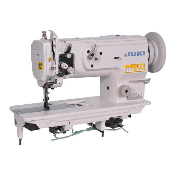
1-NEEDLE, UNISON FEED, LOCKSTITCH MACHINE
(AUTOMATIC LUBRICATION)
LU-1510N
1-NEEDLE, UNISON FEED, LOCKSTITCH MACHINE WITH AUTOMATIC THREAD
TRIMMER (AUTOMATIC LUBRICATION)
LU-1510N-7, LU-1511N-7
1-NEEDLE, UNISON FEED, LOCKSTITCH MACHINE
LU-1508N, LU-1509N
1-NEEDLE, UNISON FEED, LOCKSTITCH MACHINE (FOR EXTRA HEAVY-WEIGHT MATERIALS)
LU-1508NH, LU-1509NH
2-NEEDLE, UNISON FEED, LOCKSTITCH MACHINE (AUTOMATIC LUBRICATION)
LU-1560N, LU-1561N
2-NEEDLE, UNISON FEED, LOCKSTITCH MACHINE WITH AUTOMATIC THREAD
TRIMMER (AUTOMATIC LUBRICATION)
LU-1560N-7, LU-1561N-7
2-NEEDLE, UNISON FEED, LOCKSTITCH MACHINE WITH ORGANIZED SPLIT NEEDLE BAR
LU-1565N
ENGINEER'S MANUAL
29340700
No.E337-02
Advertisement
Table of Contents

Related Manuals for JUKI LU-1510N


Summary of Contents for JUKI LU-1510N
- Page 1 1-NEEDLE, UNISON FEED, LOCKSTITCH MACHINE (AUTOMATIC LUBRICATION) LU-1510N 1-NEEDLE, UNISON FEED, LOCKSTITCH MACHINE WITH AUTOMATIC THREAD TRIMMER (AUTOMATIC LUBRICATION) LU-1510N-7, LU-1511N-7 1-NEEDLE, UNISON FEED, LOCKSTITCH MACHINE LU-1508N, LU-1509N 1-NEEDLE, UNISON FEED, LOCKSTITCH MACHINE (FOR EXTRA HEAVY-WEIGHT MATERIALS) LU-1508NH, LU-1509NH 2-NEEDLE, UNISON FEED, LOCKSTITCH MACHINE (AUTOMATIC LUBRICATION)
- Page 2 PREFACE This Engineer’s Manual is written for the technical personnel who are responsible for the service and maintenance of the machine. The Instruction Manual for these machines intended for the maintenance personnel and operators at an apparel factory contains operating instructions in detail. And this manual describes “Standard Adjustment”, Adjustment Procedures”, “Results of Improper Adjustment”, and other important information which are not covered in the Instruction Manual.
-
Page 3: Table Of Contents
CONTENTS 1. SPECIFICATIONS ....................1 2. STANDARD ADJUSTMENT ................... 6 (1) Needle entry position ......................6 (2) Longitudinal position of the feed dog ..................6 (3) Lateral position of the feed dog ....................8 (4) Height of the feed dog ......................8 (5) Height of the hook .........................10 (6) Adjusting the inner hook guide ..................... -
Page 4: Lubrication Route Diagram
3. INSTALLATION OF THE OPTIONAL PARTS ............50 (1) DL device (For the machine with thread trimmer only) ............50 (2) Thread trimmer Ver.UP set (Part No. for 1-needle : 21389259, Part No. for 2-needle : 21389267) ... 51 (3) Bobbin thread remaining amount detecting device (AE-10A Kit Part No. : GAE10000AA0) ..51 (4) Automatic reverse feed device ....................52 1) Removing the window plate (Removing parts list) .................... -
Page 5: Specifications
Timing belt actuation mechanism Lubrication Automatic lubrication (partially by manual) Lubricating oil JUKI New Defrix Oil No. 2 (equivalent to ISO standard VG32) Cylinder bed diameter 517 mm x 178 mm Free space for sewing 255 mm x 99 mm Size of handwheel V belt effective diameter : ø93.3 mm... - Page 6 Cam-driven scissors type mechanism Lubrication Automatic lubrication (partially by manual) Lubricating oil JUKI New Defrix Oil No. 2 (equivalent to ISO standard VG32) Cylinder bed diameter 517 mm x 178 mm Free space for sewing 255 mm x 99 mm Size of handwheel V belt effective diameter : ø93.3 mm...
- Page 7 Timing belt actuation mechanism Lubrication By manual (Centralized tank lubrication system) Lubricating oil JUKI New Defrix Oil No. 2 (equivalent to ISO standard VG32) Cylinder bed diameter 517 mm x 178 mm Free space for sewing 255 mm x 99 mm Size of handwheel V belt effective diameter : ø93.3 mm...
- Page 8 Cam-driven scissors type mechanism Lubrication Automatic lubrication (partially by manual) Lubricating oil JUKI New Defrix Oil No. 2 (Equivalent to ISO standard VG32) Cylinder bed diameter 517 mm x 178 mm Free space for sewing 255 mm x 99 mm Size of handwheel V belt effective diameter : ø93.3 mm...
- Page 9 Thread trimming – mechanism Lubrication By manual Lubricating oil JUKI New Defrix Oil No. 2 (Equivalent to ISO standard VG32) Cylinder bed diameter 517 mm x 178 mm Free space for sewing 255 mm x 99 mm Size of handwheel V belt effective diameter : ø93.3 mm...
-
Page 10: Standard Adjustment
Standard Adjustment Model DimennsionA LU-1561N-7 11.5±0.1mm LU-1511N-7 11±0.1mm Top surface of throat plate LU-1509N LU-1561N 10±0.1mm LU-1509NH Standard LU-1510N-7 9±0.1mm gauge type LU-1560N-7 LU-1560N LU-1508N 8.5±0.1mm LU-1510N LU-1508NH 8±0.1mm LU-1565N Top surface of throat plate Conditions • Needle bar at lowest dead... - Page 11 Adjustment Procedures Results of Improper Adjustment 1. Set the stitch dial to “0”. ™ Stitch skipping or needle 2. Turn the handwheel to bring the needle bar to the lowest dead breakage will result. point of its stroke. ™ Poorly tensed stitches will result. 3.
-
Page 12: Lateral Position Of The Feed Dog
Adjust so that A = B and C = D are almost obtained. (4) Height of the feed dog Standard Adjustment Model Dimension A LU-1509N 0.4 to 0.5 mm LU-1509NH LU-1510N-7 LU-1511N-7 LU-1560N-7 LU-1561N LU-1561N-7 LU-1508N 0.8 to 0.9 mm LU-1508NH LU-1510N... - Page 13 Adjustment Procedures Results of Improper Adjustment 1. Set the stitch dial to “0”. ™ S t i t c h s k i p p i n g o r t h r e a d 2. Turn the handwheel to bring the needle bar to the lowest dead breakage will result.
-
Page 14: Height Of The Hook
(5) Height of the hook Standard Adjustment Hook stopper section (6) Adjusting the inner hook guide Standard Adjustment Model Dimension A LU-1510N-7 0.1 to 0.2 mm LU-1511N-7 LU-1560N-7 LU-1561N-7 LU-1508N 0.1 to 0.3 mm LU-1509N LU-1508NH LU-1509NH LU-1510N LU-1560N LU-1561N... - Page 15 Adjustment Procedures Results of Improper Adjustment 1. Loosen two setscrews 1 in the screw gear (small). ™ S t i t c h s k i p p i n g o r t h r e a d 2. Draw out hook 2 in the direction of the arrow. (At this time, breakage will result.
-
Page 16: Needle-To-Hook Timing
(7) Needle-to-hook timing Standard Adjustment Model Dimension A LU-1510N-7 58.7 mm LU-1511N-7 57.7 mm LU-1508N 56.7 mm LU-1510N LU-1509N 55.7 mm LU-1561N-7 55.9 mm LU-1560N-7 56 mm LU-1561N 53.9 mm LU-1560N 54 mm LU-1508NH 52.3 mm LU-1509NH 51.3 mm Screw gear (large) - Page 17 5. Adjust the distance from the lower end of needle bar frame to the lower end of the needle bar to dimension A. Then tighten clamping screw 2 in the needle bar holder. (For LU-1510N-7, there is an engraved marker line in needle bar 1.) 2) Needle-to-blade point of hook timing 1.
-
Page 18: Lift Of The Presser Foot
(8) Lift of the presser foot Standard Adjustment 1) Hand lifter Top surface of throat plate Condition • State that the hand lifter is raised 2) Knee lifter (Without thread trimmer only) Knee lifter lever A Knee lifter lever B Conditions : Lifting amount when stopper screw 6 comes in contact with knee lifter lever A... - Page 19 Adjustment Procedures Results of Improper Adjustment 1) Hand lifter When the lifting amount is higher 1. Loosen setscrew 3 in the side cover located at the anti- than the specified value : operator's side of the machine arm and remove side cover 4. ™...
-
Page 20: Automatic Presser Foot Lifter (Machine With Thread Trimmer Only)
Standard Adjustment 3) Automatic presser foot lifter (Machine with thread trimmer only) Top surface of throat plate (9) Timing between the upper shaft and the lower shaft Standard Adjustment To be parallel Conditions • Feed amount : 0 mm • Needle bar at lowest dead point –... - Page 21 Adjustment Procedures Results of Improper Adjustment 3) Automatic presser foot lifter (Machine with thread trimmer When the lifting amount is higher only) than the specified value : 1. Loosen cylinder nut 1 and adjust the screwing amount of ™ The top end of the needle bar cylinder connecting screw 2 so that the height from the top interferes with the walking foot surface of the throat plate to the bottom surface of the presser...
-
Page 22: Feed Cam Timing
(10) Feed cam timing Standard Adjustment 1) Horizontal feed cam timing ™ In case of LU type machines other than LU-1508NH and LU-1509NH Main shaft Screw No. 1 Conditions • Feed amount : maximum • Needle bat at lowest dead point ™... - Page 23 Adjustment Procedures Results of Improper Adjustment 1) Horizontal feed cam timing ™ Pitch error at high or low speed is apt to occur. ™ In case of LU typre machines other than LU-1508NH and ™ Needle thread tension will vary. LU-1509NH ™...
-
Page 24: Top Feed Cam Timing
Standard Adjustment 2) Top feed cam timing ™ In case of the machine without thread trimmer Main shaft Screw No. 1 Screw No. 2 To align Conditions • Feed amount : 6 mm • When needle and walking foot are lowered. ™... - Page 25 Adjustment Procedures Results of Improper Adjustment 2) Top feed cam timing ™ Pitch error at high or low speed ™ In case of the machine without thread trimmer is apt to occur. 1. Set the stitch dial to “6”. 2. Adjust the amount of alternate vertical movement of both the walking foot and the presser foot to the standard (the lower engraved marker line on the top feed rear arm aligns with the center of the hinge screw).
-
Page 26: Feed Motion
(11) Feed motion Standard Adjustment 1) Amount of alternate vertical movement (position of the vertical adjusting arm) ™ In case of the machine without thread trimmer Standard of amount of alternate vertical movement Upper engraved marker line : Approx. 5 mm Center engraved marker line : Approx. - Page 27 Adjustment Procedures Results of Improper Adjustment 1) Amount of alternate vertical movement Increase the height of working in ™ In case of the machine without thread trimmer accordance with the sewing 1. Loosen the window plate setscrew and remove the window products.
-
Page 28: Alternate Momentum
Standard Adjustment 2) Alternate momentum Top surface of Conditions feed dog • Feed amount : 0 mm Top surface of Top surface of • Amount of alternate vertical movement : standard throat plate throiat plate ™ In case of the machine without thread trimmer ™... - Page 29 Adjustment Procedures Results of Improper Adjustment 2) Alternate momentum Adjust the vertical stroke of the 1. Set the stitch dial to “0”. walking foot so that it is larger than 2. Turn the handwheel to make sure that the amount of alternate that of the presser foot in accordance vertical movement of walking foot 1 and presser foot 2 is with the sewing products.
-
Page 30: Stitch Length Of Normal/Reverse Feed
(13) Stitch length of normal/reverse feed Standard Adjustment Conditions • Feed amount : 6 mm Feed adjusting base Notched part Notch Feed adjusting rod (14) Balancer (Machine without thread trimmer only) Standard Adjustment To be equal Screws No. 1 align with each other. - Page 31 Adjustment Procedures Results of Improper Adjustment 1. Set the stitch dial to “6”. ™ Respective stitch lengths of 2. Loosen two setscrews 1 in the feed adjusting eccentric pin. normal and reverse feeds do not 3. Turn feed adjusting eccentric pin 2 to adjust the stitch match.
-
Page 32: Vertical Position Of The Needle Bar Rocking Frame
(15) Vertical position of the needle bar rocking frame Standard Adjustment Needle bar lid screw Rocking Pushing direction frame Needle stop push rod Half ring Needle bar fixing shaft Highest dead point of needle bar connection Needle bar rocking frame shaft Needle stop ball slide shaft Range of... - Page 33 Adjustment Procedures Results of Improper Adjustment 1. Loosen two setscrews 2 in the needle bar rocking frame shaft ™ Trouble of the organized split attached to needle bar rocking frame 1. needle bar occurs. 2. Pushing the needle bar rocking frame base shaft in the direction of the arrow mark, turn the needle bar rocking frame to the left or right, and the needle bar rocking frame moves up or down.
-
Page 34: Dimension Of The Needle Stop Adjusting Slide Shaft (Asm.)
(16) Dimension of the needle stop adjusting slide shaft (asm.) Standard Adjustment (17) Position of the change lever Standard Adjustment Needle stop change base 49.7 mm Thread tension base plate Change lever Change fixing lever Needle bar rocking shaft base –... - Page 35 Adjustment Procedures Results of Improper Adjustment 1. Loosen needle stop adjusting screw 1 and nut 2, turn needle ™ W h e n t h e d i m e n s i o n i s stop adjusting screw 1 to adjust the dimension to 30.9±0.1 i m p r o p e r , v a r i o u s p l a ce s mm and fix it with needle stop adjusting nut 2.
-
Page 36: Position Of The Reverse Feed Control Lever
(18) Position of the reverse feed control lever Standard Adjustment ™ In case of LU-1510N-7, LU-1511N-7, ™ In case of LU-1508N, LU-1509N, LU-1560N-7, LU-1561N-7, LU-1508NH LU-1510N, LU-1560N, LU-1561N and LU-1509NH and LU-1565N Almost level Reverse feed Feed lever shaft regulator... - Page 37 1 and reverse feed control lever stopper 2. decreased. ™ In case of LU-1508N, LU-1509N, LU-1510N, LU-1560N, LU- When the position of the reverse 1561N and LU-1565N feed control lever is high 1.
-
Page 38: Reverse Feed Cylinder
(20) Reverse feed cylinder Standard Adjustment 7 to 8 mm Feed adjusting rod Hinge screw (21) Lubrication Standard Adjustment 1) In case of manual lubrication Oil surface Decrease Increase Drawing of top surface of machine arm A sheet of paper –... - Page 39 Adjustment Procedures Results of Improper Adjustment 1. Loosen nut 1. ™ When the fork section does not 2. Turn the shaft of cylinder 5 and adjust so that the distance enter the hinge screw, stitches from the end of shaft of cylinder 5 to cylinder connecting screw of the reverse feed may not be 2 should be 7 to 8 mm.
-
Page 40: In Case Of Automatic Lubrication
Standard Adjustment 2) In case of automatic lubrication Increase Decrease A sheet of paper Drawing of top surface of machine arm – 36 –... - Page 41 When the amount of oil is too much 3. Pour the JUKI New Defrix Oil No. 2 into the oil tank 1 until ™ Thread is stained with oil. In HIGH level is reached. addition, the cloth may be 4.
-
Page 42: Thread Trimmer Device
Conditions : Make the edge of counter knife come in contact with the step difference of counter knife base. Dimension Left Right Model Dimension A Dimension B Dimension A Dimension B LU-1510N-7 – – 23.2±0.1 mm 3.5±0.1 mm LU-1511N-7 – – LU-1560N-7 21.3±0.1 mm 4.5±0.1 mm... - Page 43 Position of left clamp Position of right clamp deformation of clamp spring or spring spring the like occurs. LU-1510N-7 Thickness of part A is 3.5 LU-1511N-7 mm. Insert this part between counter knife 3 and clamp spring 5, and adjust clamp spring 5 so LU-1560N-7 Thickness of part B is 4.5...
-
Page 44: Position Of The Counter Knife Base
To contact Dimension C 1.5 mm Condition : Make the edge of counter knife Dimension Dimension C Dimension D Model base come in contact with the LU-1510N-7 1.5.±0.2 mm – step difference of hook shaft LU-1511N-7 base. LU-1560N-7 2±0.2 mm LU-1561N-7... - Page 45 Adjustment Procedures Results of Improper Adjustment 2) Position of the counter knife base When dimension C or D is larger 1. Loosen setscrews 1 in the counter knife base. ™ Knife pressure is increased and 2. Use counter knife gauge 2 supplied as accessories and move motor stop will be caused.
-
Page 46: Adjusting The Knife Pressure
Standard Adjustment 4) Adjusting the knife pressure ™Knife pressure Conditions : Moving knife and counter knife come in contact with each other. : Rocking arm and stopper plate come in close contact with each other. ™Initial position Close contact 5) Thread trimmer cam Conditions : Thread trimmer driving plate comes in close contact with follower installing base. - Page 47 Adjustment Procedures Results of Improper Adjustment 4) Adjusting the knife pressure When the knife pressure is high 1. Loosen setscrews 1 in the moving knife. ™ Blade sections of the counter knife and the moving knife may 2. Adjust the installing position of the moving knife so that the position where moving knife 2 and counter Knife 3 start be damaged.
-
Page 48: Thread Trimmer Cam Timing
Standard Adjustment 6) Thread trimmer cam timing Engraved marker dot Red engraved on machine arm marker dot Hook driving shaft Section R Close contact Handwheel Close contact Conditions : Engr ave d m ar ke r do t o n the handwheel aligns with engraved marker dot on machine arm. - Page 49 Adjustment Procedures Results of Improper Adjustment 6) Thread trimmer cam timing When thread trimming timing is 1. Loosen setscrews 4 in the thread trimmer cam which have retarded ™ Thread trimming action does not been temporarily tightened at "5) Thread trimmer cam". complete even at the needle-up 2.
-
Page 50: Connecting The Left And Right Rocking Arms (2-Needle Machine Only)
Standard Adjustment 8) Connecting the left and right rocking arms (2-needle machine only) Condition : When the moving knife is positioned to the initial p o s i t i o n . ( R e f e r t o Close contact “™Initial position of 4) A d j u s t i n g t h e k n i f e... - Page 51 Adjustment Procedures Results of Improper Adjustment 8) Connecting the left and right rocking arms ™ When the respective positions (2-needle machine only) are not correct, defective thread 1. Loosen setscrews 1 in the moving knife shaft connectingg trimming occurs. plate. 2.
-
Page 52: Alternate Vertical Dial
(23) Alternate vertical dial Standard Adjustment 1) Installing position of the detection switch of the amount of alternate vertical movement Sewing speed of LU-1510N-7 and LU-1511N-7 Amount of alternate vertical Stitch length : Stitch length : movement of the walking foot and... - Page 53 Adjustment Procedures Results of Improper Adjustment 1. Turn the alternate vertical dial to adjust the scale “1” to the ™ Sewing speed may not change convex section on the top cover. even when turning the alternate 2. Loosen setscrew 1 in the alternate vertical dial and remove vertical dial.
-
Page 54: Installation Of The Optional Parts
3. INSTALLATION OF THE OPTIONAL PARTS (1) DL device (For the machine with thread trimmer only) ™Installing DL device (List A) Part No. of DL21 G kit for installation after set-up of machine : GDL21000GA0 * Please order from us with the aforementioned part 1. -
Page 55: Thread Trimmer Ver.up Set (Part No. For 1-Needle : 21389259, Part No. For 2-Needle : 21389267)
Setting parameter when using SC-380 1. Change over the normal mode to C mode. 2. Change function No. I7 from no to BTL. 3. Change over the mode to the normal mode. C mode (selection : + C) : Setting of input Function name Symbol Initial value... -
Page 56: Automatic Reverse Feed Device
(4) Automatic reverse feed device 2) Removing the reverse feed control lever 1) Removing the window plate (Removing parts list) (Removing parts list) Hand Window plate A wheel Stitch dial 1. Loosen the respective setscrews in the belt cover 1. Loosen setscrew 1 in the window plate B located and remove the belt cover. -
Page 57: Installing The Reverse Feed Control Lever (List 2)
4) Installing the reverse feed control lever (List 2) Reverse feed control lever 1. Install reverse feed control lever spring bracket 1 with setscrew 2. 2. Install reverse feed control lever stopper 3 to the machine arm with setscrew 4. (In case of LU-1508NH and LU-1509NH, add washer 9 to reverse feed control lever stopper 3 and install the lever with setscrew 4.) 3. -
Page 58: Installing The Automatic Reverse Feed Device (List 3)
5) Installing the automatic reverse feed device (List 3) 1. Install reverse feed link 2 to reverse feed link installing base 1 with reverse feed link hinge screw 2. Install straight joint 5 to the inlet port of reverse feed cylinder 4 and install muffler 6 to the exhaust port. -
Page 59: Installing The Touch-Back Switch (List 4)
6) Installing the touch-back switch (List 4) 1. Install touch-back switch 1 with washer 3 and setscrew 2. Installing parts list of touch-back switch (List 4) Note Part No. Name of part Q’ty 21348859 Touch-back switch SS7110840SP Switch installing plate setscrew WP0501016SD Washer 7) Installing the pneumatic components (List 5) -
Page 60: Automatic Presser Foot Lifter
(5) Automatic presser foot lifter 1) Installing the automatic presser foot lifter (List A) !4 ! 5 1.Remove the side plate located on the anti-operator’s side of the machine arm. (List of the parts to be removed) 2. Install two elbows !0 to automatic presser foot lifter cylinder 1. 3. -
Page 61: Installing The Pneumatic Device Components
In case of installing the automatic reverse feed device and the automatic presser foot lifter after set-up of machine Pneumatic device components (List B) ™ Pneumatic device used : AK-119A and AK-119B ¡ Install the device above in the form of adding to the pneumatic components of the automatic reverse feed device. -
Page 62: Parts List
3) Parts List Removing parts list Note Part No. Name of part Q’ty 21332309 Side plate cover SS4110815SP Side plate cover setscrew Removing parts list Set part No. of automatic presser foot lifter (Caution : These set part Nos. are the set part Nos. of the parts from List A to List D.) Set part No. -
Page 63: Portion To Which Locktite Is Applied
4. PORTION TO WHICH LOCKTITE IS APPLIED LOCKTITE has been applied to the following parts at the time of assembly at the factory. Avoid disassembling these parts to the most. When an assembly which includes the aforementioned parts has been forced to be disassembled, be sure to wash the LOCKTITE applied part using a paint thinner or the like, and reassemble it using LOCKTITE after removing any moisture from the mating faces. -
Page 64: Selective Parts And Consumable Parts
Ditto 10112506 t=1.6 mm Ditto 10102605 t=1.7 mm Ditto 10102704 t=1.8 mm ™ For LU-1508N, LU-1509N and LU-1510N ™ For LU-1508NH and LU-1509NH Consumable part Part No. Remarks Consumable part Part No. Remarks Needle MC372001600 S C H M E T Z... -
Page 65: Engraved Marker Dots On The Handwheel (For The Machine With Thread Trimmer Only)
Needle-up stop position at the time of reverse revolution to lift needle (colorless) Range of needle-up stop position (white) Adjustment of thread Needle-down stop trimmer cam (red) position (yellow) 7. LUBRICATION ROUTE DIAGRAM LU-1510N, LU-1560N, LU-1561N LU-1510N-7, LU-1511N-7, LU-1508N, LU-1509N, LU-1560N-7, LU-1561N-7 LU-1508NH, LU-1509NH –61 –... -
Page 66: Machine Head Wiring (For The Machine With Thread Trimmer Only)
8. MACHINE HEAD WIRING (FOR THE MACHINE WITH THREAD TRIMMER ONLY) (1) Connectors coming from machine head ™6-pin connector ™12-pin connector Name of part Pin No. Remarks Name of part Pin No. Remarks Thread trimmer solenoid Synchronizer SGND (Black) Thread trimmer solenoid –... -
Page 67: Connectors Coming From The Relay Cable (Connecting Side To The Control Box)
(3) Connectors coming from the relay cable (Connecting side to the control box) * Relay cable C (asm.) : 21390950 * Relay cable D (asm.) : 21391057 ™14-pin connector Pin No. Relay cable C (asm.) Relay cable D (asm.) Thread trimming (–) (Red) Thread trimming (–) (Orange) ------- 2P LED (–) (Black) - Page 68 ™6-pin connector Pin No. Relay cable C (asm.) Relay cable D (asm.) ------- ------- INA (White) S6 (White) +12V (Red) +12V (Red) ------- INB (Black) CKU (Black) CKU (Black) ------- ------- ™2-pin connector Pin No. Relay cable C (asm.) Relay cable D (asm.) AK (–) (Black) AK (–) (Black) AK (+) (White)
-
Page 69: Table Of Troubles And Corrective Measures
9. TABLE OF TROUBLES AND CORRECTIVE MEASURES (1) With reagard to sewing Troubles Causes Checking Corrective measures Thread breakage Thread path, needle Check the sharp edge or Remove the sharp edges or burrs point, hook blade point or burr on the respective on the blade point of hook using i n n e r h o o k r e s t i n g parts. - Page 70 Troubles Causes Checking Corrective measures Stitch skipping Clearance between the Check the clearance. Refer to “(7) Needle-to-hook needle and the blade timing”. point of hook is too large. Needle-to-hook timing is Check the specified Refer to “(7) Needle-to-hook excessively advanced or dimension.
- Page 71 Troubles Causes Checking Corrective measures Loose stitches Clearance between the Check the clearance. Refer to “(6) Adjusting the inner (Balloon stitches or isolated inner hook guide and the hook guide”. idling loop) protruding section of inner hook is too large. Thread paths have been Check the finish of the Finish using a fine emery paper or...
- Page 72 Troubles Causes Checking Corrective measures Irregular stitches Stroke of the thread take- Check the stroke of the Adjust the thread take-up spring to up spring is improper. thread take-up spring. move to approximately 1 mm from the initial position when hook draws thread maximumly.
-
Page 73: With Regard To Thread Trimming
(2) With regard to thread trimming Troubles Causes Checking Corrective measures One or serveral stitches Thread remaining at the Check the routing of T h r e a d t h e n e e d l e t h r e a d skip at the start of sewing. - Page 74 Troubles Causes Checking Corrective measures Thread slips off the needle Needle thread slips off the C h e c k w h e t h e r t h e Refer to the Cause “Needle eyelet. needle eyelet immediately needle thread remaining thread remaining at the needle top after thread trimming.
- Page 75 Troubles Causes Checking Corrective measures From the previous page From the previous page Adjust the tension of bobbin Tension of the bobbin thread. thread is too high. Refer to "(22)-4) Adjusting the Knife pressure of the counter knife is too high. knife pressure".
- Page 76 Troubles Causes Checking Corrective measures From the previous page Refer to "(22)-4) Adjusting the Both needle and bobbin The blades of moving knife pressure". t h r e a d c a n n o t b e knife and counter knife trimmed.
- Page 77 –73 –...
- Page 78 – 74 –...
-
Page 79: Drawing Of The Table
Style of tpe : Helvetica Reg. Condensed Thickness : 1.5 Condensed voided letters (on the reverse side) Thickness : 0.5 3 JUKI logotype Thickness : 1.5 Thickness : 0.8 4 16 depth 30 5 Top surface C1.5 6 18 drill 7 3-ø13 drilled hole... - Page 80 FAX : (81)3-3430-4909 • 4914 • 4984 The description covered in this engineer's manual is subject to change for improvement of the TELEX : J22967 commodity without notice. Copyright C 2002 JUKI CORPORATION. All rights reserved throughout the world. 02 · 10 Printed in Japan (E)