Pioneer XV-HTD1 Service Manual
Dvd receiver
Hide thumbs
Also See for XV-HTD1:
- Operating instructions manual (53 pages) ,
- Operating instructions manual (52 pages)
Table of Contents
Advertisement
DVD RECEIVER
XV-HTD1
THIS MANUAL IS APPLICABLE TO THE FOLLOWING MODEL(S) AND TYPE(S).
Model
Type
XV-HTD1
MYXJ
NVXJ
This product is component of system.
Component
DVD SURROUND SYSTEM
DVD RECEIVER
SPEAKER SYSTEM
CONTENTS
1. SAFETY INFORMATION ....................................... 2
2. EXPLODED VIEWS AND PARTS LIST ................. 3
4. PCB CONNECTION DIAGRAM ........................... 46
5. PCB PARTS LIST ................................................ 66
6. ADJUSTMENT ..................................................... 73
7. GENERAL INFORMATION ................................ 74
7.1 DIAGNOSIS .................................................. 74
PICKUP DEFECTIVE ........................... 74
7.1.2 TEST POINTS LOCATION ................... 75
PIONEER CORPORATION
PIONEER ELECTRONICS SERVICE, INC. P.O. Box 1760, Long Beach, CA 90801-1760, U.S.A.
PIONEER EUROPE NV Haven 1087, Keetberglaan 1, 9120 Melsele, Belgium
PIONEER ELECTRONICS ASIACENTRE PTE. LTD. 253 Alexandra Road, #04-01, Singapore 159936
c
PIONEER CORPORATION 2001
Power Requirement
AC220-230V
AC230V
System
XV-HTD1
S-HTD1
4-1, Meguro 1-chome, Meguro-ku, Tokyo 153-8654, Japan
Region No.
2
2
Service Manual
RRV2460
This service manual
RRV2456
7.1.3 TEST MODE SCREEN DISPLAY ........ 76
7.1.4 POWER ON SEQUENCE .................... 78
7.1.5 TROUBLE SHOOTING ........................ 79
7.1.6 ERROR CODE ..................................... 80
7.1.7 DISASSEMBLY .................................... 84
MECHANISM SECTION ....................... 95
7.2 PARTS .......................................................... 98
7.2.1 IC .......................................................... 98
7.2.2 DISPLAY ............................................. 117
ORDER NO.
RRV2460
Remarks
Remarks
T - ZZK MAY 2001 Printed in Japan
Advertisement
Table of Contents
Troubleshooting

Related Manuals for Pioneer XV-HTD1


Summary of Contents for Pioneer XV-HTD1
-
Page 1: Table Of Contents
PIONEER CORPORATION 4-1, Meguro 1-chome, Meguro-ku, Tokyo 153-8654, Japan PIONEER ELECTRONICS SERVICE, INC. P.O. Box 1760, Long Beach, CA 90801-1760, U.S.A. PIONEER EUROPE NV Haven 1087, Keetberglaan 1, 9120 Melsele, Belgium PIONEER ELECTRONICS ASIACENTRE PTE. LTD. 253 Alexandra Road, #04-01, Singapore 159936 PIONEER CORPORATION 2001 T –... -
Page 2: Safety Information
XV-HTD1 1. SAFETY INFORMATION WARNING THE AEL(ACCESSIBLE EMISSION LEVEL) OF THE LASER POWER OUTPUT IS LESS THAN CLASS 1 BUT THE LASER COMPONENT IS CAPABLE OF EMITTING RADIATION EXCEEDING THE LIMIT FOR CLASS1. A SPECIALLY INSTRUCTED PERSON SHOULD DO SERVICING OPERATION OF THE APPARATUS. -
Page 3: Exploded Views And Parts List
Operating Instructions See Contrast table (2) (Dutch/Swedish/Portuguese) Operating Instructions See Contrast table (2) (Spanish) FRONT (2) CONTRAST TABLE XV-HTD1/MYXJ and NVXJ are constructed the same except for the following : Part No. Mark Symbol and Description XV-HTD1 XV-HTD1 Remarks /MYXJ... - Page 4 XV-HTD1 2.2 EXTERIOR Refer to "2.4 TABLE MECHANISM SECTION". Refer to "2.3 FRONT PANEL SECTION".
- Page 5 Bonnet Case XZN3118 Front Frame XNG3056 PCB Angle XNG3057 Mecha Frame XNG3059 (2) CONTRAST TABLE XV-HTD1/MYXJ and NVXJ are constructed the same except for the following : Part No. Mark Symbol and Description XV-HTD1 XV-HTD1 Remarks /MYXJ /NVXJ Rear Panel...
- Page 6 XV-HTD1 2.3 FRONT PANEL SECTION 14(1/2) 14(2/2) FRONT PANEL SECTION PARTS LIST Mark No. Description Part No. Mark No. Description Part No. 1 JOG Assy XWZ3448 Function Button XAD3100 2 KEYB Assy XWZ3447 Power Button XAD3101 3 DISC KEY Assy...
- Page 7 XV-HTD1 2.4 TABLE MECHANISM SECTION 37 (2/6 - 5/6) [Roller Cover] 37 (1/6) From 37 (6/6) DVDM CN555 [PCB Cover] Refer to "2.5 TRAVERSE MECHANISM ASSY-S". From DVDM CN2...
- Page 8 XV-HTD1 TABLE MECHANISM SECTION PARTS LIST Mark No. Description Part No. 1 5C Mech. Base Assy XXA3027 2 5C Table Mech. Assy VWT1175 3 TRSB Assy XWZ3461 4 SSRB Assy XWZ3462 5 LOMB Assy XWZ3463 6 Traverse Mechanism Assy-S VXX2653...
- Page 9 XV-HTD1 2.5 TRAVERSE MECHANISM ASSY-S • Top View DVDM Assy TRAVERSE MECHANISM ASSY-S PARTS LIST Mark No. Description Part No. Mark No. Description Part No. SMEB Assy VWG2048 Hook VNL1770 FGSB Assy VWG2009 FFC Holder VNL1802 Motor (CARRIAGE) VXM1079 Mechanism Base...
-
Page 10: Block Diagram And Schematic Diagram
XV-HTD1 3. BLOCK DIAGRAM AND SCHEMATIC DIAGRAM 3.1 BLOCK DIAGRAM DVDM ASSY CN555 (24P) (24P) IC18 SD0-SD7 57-60 80-84 IC12 MB86373B Spindle DSP RF 63-66 78,86,87 OEIC PE5108A Motor CDDATA MPEG2 LA9701M DVD DECODER DECODER SREQ BY CHIP AV-1 XSACK... -
Page 11: Video Assy
XV-HTD1 VIDEO ASSY IC5351 LA7138M VIDEO AMP CN8501 CN5352 CN5351 CN15 JA5351 (30P) (11P) (11P) (30P) (VCB) (VCB) (VCB) (VCB) VIDEO OUT V/Cb VIDEO VIDEO FILTER C/Cr C/Cr CN5352 AODAI S-VIDEO OUT AC-3 (DVD) (DVD) JA5103 (DI) (DI) DIGITAL IN... -
Page 12: Overall Wiring Diagram
XV-HTD1 3.2 OVERALL WIRING DIAGRAM TUNER MODULE (AXQ7229) INPUT ASSY (XWZ3456) AC 220-230V 50/60Hz LIVE PICKUP ASSY (VWY1055) NEUTRAL POWER CORD MYXJ : ADG1154 NVXJ : ADG1156 PRIMARY ASSY (XWZ3433) FGSB ASSY SMEB ASSY (VWG2009) (VWG2048) LOMB ASSY 5CH MECH.BASE ASSY... - Page 13 XV-HTD1 Note : When ordering service parts, be sure to refer to "EXPLODED VIEWS and PARTS LIST" or "PCB PARTS LIST". 1/2- VIDEO ASSY DSP ASSY (XWX3040) (XWZ3460) DC FAN MOTOR AXM7014 1/3- DVDM ASSY (XWX3034) FRONT AMP ASSY (XWZ3439)
- Page 14 XV-HTD1 3.3 TRSB, SSRB, LOMB, SMEB and FGSB ASSYS SSRB ASSY (XWZ3462) : The power supply is shown with the marked box. TRSB ASSY (XWZ3461) LOMB ASSY (XWZ3463) CARRIAGE MOTOR (LOADING) : VXM1033 A B C...
- Page 15 XV-HTD1 : SLIDER SERVO LOOP LINE FGSB ASSY (VWG2009) SMEB ASSY (VWG2048) CARRRIAGE MOTOR ASSY : VXX2650 SPINDLE MOTOR ASSY : VXX2649...
- Page 16 XV-HTD1 3.4 DVDM ASSY (1/3) CN31 CN202...
- Page 17 XV-HTD1 DVDM ASSY (XWX3034) : RF SIGNAL ROUTE : RF VIDEO SIGNAL ROUTE : RF AUDIO SIGNAL ROUTE (AD) : AUDIO DATA SIGNAL ROUTE : FOCUS SERVO LOOP LINE : TRACKING SERVO LOOP LINE : SLIDER SERVO LOOP LINE 10 11...
- Page 18 XV-HTD1 3.5 DVDM ASSY (2/3) DVDM ASSY (XWX3034) : RF VIDEO SIGNAL ROUTE (VD) : VIDEO DATA SIGNAL ROUTE (AD) : AUDIO DATA SIGNAL ROUTE VYW3003 (VD) (VD) (AD)
- Page 19 XV-HTD1 1/3, 3/3 1/3, 3/3 20MHz VNK1626 : The power supply is shown with the marked box.
- Page 20 XV-HTD1 3.6 DVDM ASSY (3/3) (VD) (DVD) AV-1 MPEG2 DECODER (DVD) 14 17 13 16 12 15 (AD) (VCB)
- Page 21 XV-HTD1 DVDM ASSY (XWX3034) (VD) : VIDEO DATA SIGNAL ROUTE (VCB) : VCB SIGNAL ROUTE : Y SIGNAL ROUTE : C SIGNAL ROUTE (AD) : AUDIO DATA SIGNAL ROUTE (DVD) : DVD AUDIO SIGNAL ROUTE (DVD) (DVD) (DVD) (VCB) (VCB)
- Page 22 XV-HTD1 3.7 FRONT AMP ASSY FRONT AMP ASSY (XWZ3439) : The power supply is shown with the marked box.
- Page 23 XV-HTD1 MYXJ, NVXJ Not used (FL) : FL AUDIO SIGNAL ROUTE (SW) : SW AUDIO SIGNAL ROUTE...
- Page 24 XV-HTD1 3.8 REAR AMP ASSY REAR AMP ASSY (XWZ3443) : The power supply is shown with the marked box.
- Page 25 XV-HTD1 (SL) : SL AUDIO SIGNAL ROUTE : C AUDIO SIGNAL ROUTE MYXJ, NVXJ...
- Page 26 XV-HTD1 3.9 MAIN ASSY (1/3) MAIN ASSY (XWX3031) : The power supply is shown with the marked box.
- Page 27 XV-HTD1 2/3, 3/3 2/3, 3/3 2/3, 3/3 CAUTION : FOR CONTINUED PROTECTION AGAINST RISK OF FIRE. CAUTION : FOR CONTINUED PROTECTION AGAINST RISK OF FIRE. REPLACE ONLY WITH SAME TYPE NO. 491010 MFD, BY REPLACE ONLY WITH SAME TYPE NO. 4910.75 MFD, BY LITTELFUSE INC.
- Page 28 XV-HTD1 3.10 MAIN ASSY (2/3) MAIN ASSY (XWX3031) CN5208 CN5351...
- Page 29 XV-HTD1 CN201 (VCB) (HP) (SW) (DVD) : VCB SIGNAL ROUTE : HP AUDIO SIGNAL ROUTE : SW AUDIO SIGNAL ROUTE : DVD AUDIO SIGNAL ROUTE (TX) (DI) (SL) : DI AUDIO SIGNAL ROUTE : TX AUDIO SIGNAL ROUTE : Y SIGNAL ROUTE...
- Page 30 XV-HTD1 3.11 MAIN ASSY (3/3) MAIN ASSY (XWX3031) MYXJ, NVXJ CN5802 CN5801...
- Page 31 XV-HTD1 MYXJ,NVXJ CN5807 1.6V 2.5V 1.6V 2.5V CN55 2.5V LEVEL SHIFT CN11 3.1V 3.1V FOR DOWNLOAD (DVD) (VCB) : DVD AUDIO SIGNAL ROUTE : VCB SIGNAL ROUTE (HP) : HP AUDIO SIGNAL ROUTE : Y SIGNAL ROUTE : TRAY POSITION SERVO LOOP LINE...
- Page 32 XV-HTD1 3.12 TUNER MODULE TUNER MODULE (AXQ7229) FM FRONT END (FM) (FM) (FM) (FM) (FM) (AM) (AM) (AM) MW RF TUNING BLOCK (FM) (AM) OSC : 981 - 2052kHz 9k step...
- Page 33 XV-HTD1 : The power supply is shown with the marked box. (TX) : AUDIO SIGNAL ROUTE (TUNER) (AM) : AM SIGNAL ROUTE (FM) : FM SIGNAL ROUTE (AM) (TX) (FM) (TX) (TX) (TX) (FM) (FM) (TX) (AM) L201 ATE7003...
- Page 34 XV-HTD1 3.13 INPUT and VIDEO ASSYS INPUT ASSY (XWZ3456) MYXJ,NVXJ VIDEO ASSY (XWZ3460) MYXJ,NVXJ...
- Page 35 XV-HTD1 CN3703 CN5209 : The power supply is shown with the marked box. (VCB) (VCB) CN5352 MYXJ,NVXJ (VCB) (VCB) (TX) (VCB) (AI) (DVD) : TX AUDIO SIGNAL ROUTE : VCB SIGNAL ROUTE : AUX IN AUDIO SIGNAL ROUTE : DVD AUDIO SIGNAL ROUTE...
- Page 36 XV-HTD1 3.14 DSP ASSY (1/2) DSP ASSY (XWX3040) CN5503 CN3001 CN5207 : The power supply is shown with the marked box.
- Page 37 XV-HTD1 (SL) (DVD) : AUDIO SIGNAL ROUTE : SL AUDIO SIGNAL ROUTE : DVD AUDIO SIGNAL ROUTE (DI) : DI AUDIO SIGNAL ROUTE : C AUDIO SIGNAL ROUTE (FL) (SW) : FL AUDIO SIGNAL ROUTE : SW AUDIO SIGNAL ROUTE...
- Page 38 XV-HTD1 3.15 DSP ASSY (2/2) (FL) (FL) (FL) DSP ASSY (XWX3040) (SL) (SL) (SL) (SW) (SW) (SW)
- Page 39 XV-HTD1 (FL) (FL) (FL) : FL AUDIO SIGNAL ROUTE (SL) : SL AUDIO SIGNAL ROUTE : C AUDIO SIGNAL ROUTE (SW) : SW AUDIO SIGNAL ROUTE (SL) (SL) (SW) (SW)
- Page 40 XV-HTD1 3.16 DISPLAY, MIC HP, KEYB, STBY SWITCH, JOG and DISC KEY ASSYS CN5509 CN5511 DISPLAY ASSY (XWZ3446) DISC KEY ASSY (XWZ3449)
- Page 41 XV-HTD1 SWITCHES JOG ASSY KEYB ASSY S5802 : ¡•¢ (FORWARD) S5801 : VOLUME DISC KEY ASSY S5812 : DVD/CD S5803 : 0 OPEN/CLOSE S5813 : TUNER/BAND S5804 : EXCHANGE S5814 : TV/AUX S5805 : DISC SKIP S5815 : CD MODE...
-
Page 42: Primary Assy
XV-HTD1 3.17 PRIMARY ASSY XTS3052 CN5011 CN5012 CN8503 ATT7050... - Page 43 XV-HTD1 • NOTE FOR FUSE REPLACEMENT FOR CONTINUED PROTECTION AGAINST RISK OF FIRE, CAUTION - REPLACE WITH SAME TYPE AND RATINGS OF FUSE. PRIMARY ASSY (XWZ3433) FU1: REK1027 T3.15A...
- Page 44 XV-HTD1 WAVEFORMS Note : The encircled numbers denote measuring point in the schematic diagram. Measurement condition : No. 1 to 4 and 6 to 11 : MJK1, Title 1-chp 1 No. 5 : CD, ABEX-784 Track 1 No. 12 to 14 : MJK1, Title 1-chp 4 No.
- Page 45 XV-HTD1 VOLTAGES MAIN ASSY IC5501 (PDC076A) • Mode: DVD Play Pin No. Voltage (V) Pin No. Voltage (V) Pin No. Voltage (V) Pin No. Voltage -30.8 ∗ ∗ ∗ ∗ ∗ − ∗ ∗ ∗ ∗ ∗ ∗ ∗ ∗...
-
Page 46: Pcb Connection Diagram
XV-HTD1 4. PCB CONNECTION DIAGRAM NOTE FOR PCB DIAGRAMS : 1. Part numbers in PCB diagrams match those in the schematic 3. The parts mounted on this PCB include all necessary parts for diagrams. several destinations. 2. A comparison between the main parts of PCB and schematic For further information for respective destinations, be sure to diagrams is shown below. - Page 47 XV-HTD1 4.2 TUNER MODULE TUNER MODULE SIDE A CN5701 (ANP7338-B) Q202 TUNER MODULE SIDE B (ANP7338-B) Q201 IC201 Q203 Q205 IC202 Q204...
-
Page 48: Dvdm Assy
XV-HTD1 4.3 DVDM ASSY DVDM ASSY SIDE A IC23 IC11 IC15 Q121 Q101 IC21 Q103 Q5 Q102 IC18 Q109 Q107 (VNP1817-A) CN8902... - Page 49 XV-HTD1 SIDE B DVDM ASSY CN8502 CN31 IC12 IC13 IC14 Q112 IC19 Q114 Q113 Q131 Q106 IC26 IC27 Q251 (VNP1817-A) CN8501...
- Page 50 XV-HTD1 4.4 FRONT AMP ASSY FRONT AMP ASSY Q3701 CN3051 Q3714 Q3713 IC3301 IC3321 CN3053 Q3351 Q3352 Q3651 Q3372 (XNP3044-C) DC FAN MOTOR SIDE A...
- Page 51 XV-HTD1 FRONT AMP ASSY Q3703 Q3705 Q3715 Q3603 Q3302 Q3301 Q3711 Q3712 Q3717 Q3716 Q3773 Q3771 Q3774 (XNP3044-C) SIDE B...
- Page 52 XV-HTD1 4.5 REAR AMP ASSY REAR AMP ASSY Q3813 Q3702 Q3814 CN3052 IC3322 IC3401 IC5021 CN3054 IC5007 Q5021 (XNP3044-C) SIDE A...
- Page 53 XV-HTD1 REAR AMP ASSY Q3816 Q3817 Q3811 Q3704 Q3706 Q3812 Q3452 Q3815 Q3451 Q3551 Q3501 Q3401 Q3402 (XNP3044-C) SIDE B...
- Page 54 XV-HTD1 4.6 MAIN ASSY CN3302 CN3502 CN3701 MAIN ASSY CN3301 CN3501 CN3702 CN5351 CN5208 CN201 CN5807 IC14 IC13 IC18 IC3002 IC3151 IC3152 Q5721 IC15 IC3171 IC3181 IC3161...
- Page 55 XV-HTD1 CN3701 CN15 CN55 CN11 CN5802 CN5801 SIDE A (XNP3043-D) IC17 Q5501 Q5072 IC5001 IC5004 IC5005 IC5071 Q5071 Q5031 IC5081 Q5041 Q5043...
- Page 56 XV-HTD1 MAIN ASSY IC8521 IC8541 IC5501 IC8531 IC8901 Q5551-Q5554 IC5401 Q3905 Q5042 IC5081 Q5032 Q5572 Q5571 Q3906...
- Page 57 XV-HTD1 SIDE B (XNP3043-D) IC8802 Q3251 Q3253 Q3252 IC3001 Q3904 Q3903 IC5701 Q3919...
- Page 58 XV-HTD1 4.7 INPUT and VIDEO ASSYS INPUT ASSY INPUT ASSY Q5272 Q5271 CN3703 IC5353 IC5352 Q5273 Q5254 CN5209 Q5231 IC5231 Q5232 (XNP3048-C) (XNP3048-C) VIDEO ASSY VIDEO ASSY IC5104 IC5351 Q5351 Q5181 Q5171 CN5352 Q5161 (XNP3048-C) (XNP3048-C) SIDE A SIDE B...
- Page 59 XV-HTD1 4.8 DSP ASSY DSP ASSY DSP ASSY CN3001 Q8711 Q8713 Q8710 Q8712 Q8718 Q8709 Q8714 Q8715 Q8717 Q8716 IC8703 IC8705 IC8701 CN5207 IC8801 IC3751 IC3801 IC3851 CN5503 (XNP3045-C) (XNP3045-C) SIDE A SIDE B...
- Page 60 XV-HTD1 4.9 DISPLAY, MIC HP, KEYB, STBY SWITCH, JOG and DISC KEY ASSYS DISPLAY ASSY CN5509 KEYB ASSY (XNP3044-C) MIC HP ASSY CN5501 (XNP3044-C) STBY SWITCH ASSY N O P Q...
- Page 61 XV-HTD1 5509 CN5511 (XNP3044-C) JOG ASSY (XNP3044-C) (XNP3044-C) DISC KEY ASSY (XNP3044-C) SIDE A N P R S...
-
Page 62: Display Assy
XV-HTD1 DISPLAY ASSY IC5801 Q5804 Q5803 JOG ASSY KEYB ASSY (XNP3044-C) DISC KEY ASSY (XNP3044-C) SIDE B N P R S... - Page 63 XV-HTD1 (XNP3044-C) Q5802 (XNP3044-C) (XNP3044-C) MIC HP ASSY (XNP3044-C) STBY SWITCH ASSY IC5802 N O P Q...
- Page 64 XV-HTD1 4.10 PRIMARY ASSY AC IN PRIMARY ASSY IC41 CN8503 (XNP3044-C) SIDE A...
- Page 65 XV-HTD1 PRIMARY ASSY (XNP3044-C) SIDE B...
-
Page 66: Pcb Parts List
XV-HTD1 Mark No. Description Part No. Mark No. Description Part No. 5. PCB PARTS LIST • NOTES: Parts marked by "NSP" are generally unavailable because they are not in our Master Spare Parts List. • mark found on some component parts indicates the importance of the safety factor of the part. - Page 67 XV-HTD1 Mark No. Description Part No. Mark No. Description Part No. C334 CCSRCH5R0C50 C124, C132 CCSRCH680J50 FGSB ASSY C117, C240, C352, C360 CCSRCH681J25 C129, C142, C842 CEV101M10 SEMICONDUCTOR C113, C139 CEV220M16 PC101 GP2S60 C405, C413, C700, C808 CEV221M4 RESISTOR C368, C411...
- Page 68 XV-HTD1 Mark No. Description Part No. Mark No. Description Part No. FRONT AMP ASSY REAR AMP ASSY SEMICONDUCTORS SEMICONDUCTORS IC3301 STK413-000 IC5021 NJM7812FA Q3351, Q3352, Q3651 2SC2240 IC5007 NJM7912FA Q3716, Q3717 2SC2412K IC3401 STK402-230 Q3701 2SD1858X Q5021 2SB1237X Q3301, Q3302, Q3603...
-
Page 69: Main Assy
XV-HTD1 Mark No. Description Part No. Mark No. Description Part No. C5574 CEAT1R0M50 C5051, C5074, C5075 CEAT220M50 MAIN ASSY C3001, C3002 CEAT221M16 C3157, C3158, C3167, C3168, C3179 CEAT2R2M50 SEMICONDUCTORS C5033, C5703 CEAT470M16 IC5001 PROTECTOR (750mA) AEK7007 IC5005 PROTECTOR (3.5A) AEK7017... - Page 70 XV-HTD1 Mark No. Description Part No. Mark No. Description Part No. CN8501, CN8502 VKN1627 OTHERS B TO B CONNECTOR 30P CN201 13P CONNECTOR 52044-1345 CN8903 8P FFC CONNECTOR VKN1707 BN201 2P TERMINAL WITH PAL AKA7002 KN5001, KN5701 VNF1084 SHIELD CASE T...
- Page 71 XV-HTD1 Mark No. Description Part No. Mark No. Description Part No. C5354, C5356, C5360 CEAT101M16 C5105 CEAT470M16 C8715, C8716, C8727 CKSRYB122K50 C5372, C5380 CEAT471M6R3 C8713, C8714, C8725 CKSRYB152K50 C5107, C5392 CKSRYB102K50 C3707, C3708 CKSRYB222K50 C5101, C5103, C5104, C5164, C5174 CKSRYB104K25...
- Page 72 XV-HTD1 Mark No. Description Part No. Mark No. Description Part No. KEYB ASSY PRIMARY ASSY SWITCHES AND RELAYS SEMICONDUCTORS S5802, S5812-S5818 ASG7013 IC41 NJM78M56FA 2SD1859X D42, D44, D45 1SS133 RESISTORS DF06SA All Resistors RS1/16S COILS AND FILTERS OTHERS LINE FILTER...
-
Page 73: Adjustment
XV-HTD1 6. ADJUSTMENT 6.1 TUNER SECTION AM Tuner Section • There is no adjustment in the AM tuner. FM Tuner Section • Set the mode selector to FM BAND. • Connect the wiring as shown in Fig. 1. ANT. Input level and signal condition... -
Page 74: General Information
XV-HTD1 7. GENERAL INFORMATION 7.1 DIAGNOSIS 7.1.1 SELF-DIAGNOSTIC FUNCTION OF PICKUP DEFECTIVE Symptom • Indicates "No Disc" in FL display. • Player does not playback, etc.. Procedure of Self-Diagnosis → 1 Press the TEST buttons (of the test mode remote control unit : GGF1067) in the test mode screen, and turn on the laser diode (It light-up for nine seconds.). -
Page 75: Test Points Location
XV-HTD1 7.1.2 TEST POINTS LOCATION DVDM ASSY Front Side VCODR IC13 IC14 C707 SREQ TP3 (TE) IC19 TP1 (FE) VREF TP2 (RFO) IC27 IC26 VREF TP4 (FDO) R389 Short-circuit at diagnosis CN15 SIDE B... -
Page 76: Test Mode Screen Display
XV-HTD1 7.1.3 TEST MODE SCREEN DISPLAY TEST MODE SCREEN DISPLAY Consecutive double-OSD display is supported during test mode. The screen is composed 10 lines with a maximum of 32 characters per line. It can't be used with the debugging display mode together. - Page 77 XV-HTD1 (10) Output video system [V – ∗ ∗ ∗ ∗] (20) 1 Version of the flash ROM [V : ∗ . ∗ ∗ ∗] 2 Flash ROM size [FLSH = ∗] NTSC system [NTSC] PAL system [PAL ] (21) Revision of the system controller [S : ∗ . ∗ ∗ ∗ / ∗ . ∗ ∗ ]...
-
Page 78: Power On Sequence
XV-HTD1 7.1.4 POWER ON SEQUENCE Reset start • It starts when the XRESET terminal (Pin 11) is "H level". Microcomputer IC (PDC076) (MAIN ASSY : IC5501) Initialization routine Microcomputer initialization Model discrimination • The input of Pin 20 is inspected and the model discrimination is done. -
Page 79: Trouble Shooting
XV-HTD1 7.1.5 TROUBLE SHOOTING Microcomputer troubleshooting Symptom of problem Thought cause Check method • The power supply does not enter . • The microcomputer is not reset. • Whether terminal RESET (11Pin) is "H" is confirmed. • The standby LED lights even if the The operation of the RESET circuit is confirmed if POWER key is pushed. -
Page 80: Error Code
XV-HTD1 7.1.6 ERROR CODE Error codes that are displayed on the FL display without using the remote control unit FL Display Possible causes Operation of the unit The sound may not produced AV1 VER AV-1 chip is not a match with the program of system controller with the specific audio. - Page 81 XV-HTD1 Description Causes if with a DVD Causes if with a CD Operation of the of Error If normal starting was impossible in the following three cases, disc-type sensing will be retried if other errors occure excepting C5 error. However, when the focus error Disc-type- "33"...
- Page 82 XV-HTD1 Description Causes if with a DVD Causes if with a CD Operation of the Unit of Error ID can not read An ID could not be read for 1 second or more. Stop during tracing Subcode check No frame could be read for 3...
- Page 83 XV-HTD1 Error codes that are displayed on the FL display by using the remote control unit (Device error) To display : ESC + DISPLAY + DISPLAY ; Location of the display : At the two digits of left of the FL display...
-
Page 84: Disassembly
XV-HTD1 7.1.7 DISASSEMBLY DIAGNOSIS OF PCBs Note When diagnosing the unit, be sure to use two connection cables for service. (Part No : GGD1228) DVDM Assy Remove the Bonnet (Screws × 7) Power ON Tray Open (0 OPEN/CLOSE) Remove the Tray Cap... - Page 85 XV-HTD1 FRONT PANEL SECTION TABLE MECHANISM SECTION Remove the Bonnet (Screws × 7) Turn the Pickup Short SW to Short side. Power ON Tray Open (0 OPEN/CLOSE) Remove the Tray Cap Close the tray Power OFF (Pull out the Power Cord from the outlet.)
- Page 86 XV-HTD1 How to Open the Tray by Manual Operating Remove four connectors. Gear Pulley CN8903 CN555 Tray Open Gear Pulley If the tray moved toward the front about 2 or 3 cm, pull out the tray by hands. MAIN Assy...
- Page 87 XV-HTD1 TRAVERSE MECHANISM ASSY-S Disassembly Remove the Bonnet (Screws × 7) Remove the Tray Cap Remove the Front Panel Section (Refer to " FRONT PANEL SECTION") CN12 Unhook TRSB Assy Unhook Power ON Tray Open (0 OPEN/CLOSE) Note : The Traverse mechanism being Pull out the power cord from the outlet.
- Page 88 XV-HTD1 • Bottom View ×4 Release ×2 SMEB Assy FFC Holder Flexible Cable (24P) Mechanism Base Section CN202 Pickup One Screw Flexible Cable (8P) Connector Mecha Frame ×2 Unhook Traverse Mechanism Assy-S Clamper Holder Unhook Unhook One Screw Spring Exchange...
- Page 89 XV-HTD1 Assembly ×2 Hook Traverse Mechanism Assy-S Float Rubber Float Rubber Check the Float Rubbers ×4 Pole of the Float Base Float Rubber ×2 Hook Float Rubber Float Rubber Hook One Screw • Bottom View Reference Hook ×2 Styling of the Flexible Cables...
- Page 90 XV-HTD1 Rear View DVDM Assy PRIMARY Assy Side Side Open Turn it till stops Short SW Short SW Pickup Flexible Cable Pickup Flexible Cable Change Gear Planet Base Connect four connectors. Match it between first teeth of the gear. CN8903...
- Page 91 XV-HTD1 Clamper Holder Hook Spring ×4 Mechanism Base Section Mecha Frame...
- Page 92 XV-HTD1 Assemble the Tray Section to the Mechanism Base Section Confirmation : Fully turning the Planet Base to an arrow direction. Mechanism Base Section Match a convex part of the Tray section with a concave part of the Mechanism Base, and put it.
- Page 93 XV-HTD1 Important Points when Assembling the Mechanism Section Clamper Plate Tray Gear Motor (for Tray) Motor Pulley (for Tray Motor) Motor Holder Worm Gear, Tray Belt Motor (for Loading) Motor Pulley (for Loading Motor)
- Page 94 XV-HTD1 Motor (for Tray), Motor Pulley (for Tray Motor) Worm Gear and Tray Belt Adjust the height of the Motor Pulley to 2.4mm. Tray Belt Be carefull not to damage it in exchange. Motor Holder Motor Pulley 2.4mm Motor Wiring lead wires into the hook of Motor Holder.
-
Page 95: Trouble Shooting For Mechanism Section
XV-HTD1 7.1.8 TROUBLE SHOOTING FOR MECHANISM SECTION Location of Motors and Switches Carriage Motor : VXM1033 (for LOADING) Operation : Tray open → close ↓ Continuous action Traverse Mecha. clamp → unclamp * When continued turning a gear by hand Tray open →... - Page 96 XV-HTD1 Trouble Shooting Trouble Condition Condition Point Tray does not open. (Nothing works) POWER OFF Key → "OFF" indication does not disappear → "OPEN" indication does not disappear 0 (OPEN) key Loading Motor is damage, disconnection or → It becomes indication of "OPEN" from "NO DISC", 3 (PLAY) key contact defectiveness.
- Page 97 XV-HTD1 Flexible Cable (8P) (SMEB CN202 ↔ DVDM CN3) Carriage Motor : VXM1033 (for LOADING) Planet Base : VNL1874 Rotary Tray : VNK4739 Worm Gear : VNL1881 Tray position Detect Sensor (PC22 : RPI-574) Disc Detect Sensor (PC21 : GP2S28)
-
Page 98: Parts
XV-HTD1 7.2 PARTS 7.2.1 IC • The information shown in the list is basic information and may not correspond exactly to that shown in the schematic diagrams. • List of IC LC78652W, PD3410A, MB86373B, PDC076A, BA6195FP, AK4527BVQ, LC89056W-E, STK413-000 LC78652W (DVDM ASSY : IC2) •... - Page 99 XV-HTD1 • Pin Function t f i − − l l i t t i y t i t l i − − − − a i l t l i −...
- Page 100 XV-HTD1 r r i t i r − − − − l a i t f i − − l l i l i f − t l i f t l i f t l i f − −...
- Page 101 XV-HTD1 PD3410A (DVDM ASSY : IC11) • System Control IC • Pin Function − – − − − − − − – c t i − − − − − − − ← ← − − − ← c t i –...
- Page 102 XV-HTD1 − − − − − − − c t i − − c t i − c t i c t i c t i c t i − c t i − − − − − − −...
- Page 103 XV-HTD1 − t i s d i l t i s t i s − − − − − l l o l a i e l l l a i e l l − e l l − −...
- Page 104 XV-HTD1 − − − − − − − − − −...
- Page 105 XV-HTD1 MB86373B (DVDM ASSY : IC18) • MPEG2 Decoder IC • Block Diagram Exclusive 16Mbit Parallel port SDRAM Input Signal Memory System Controller Block Interface Decoder Block Internal Video Sub- Sync. Decoder picture Control Block Block Starting Signal Control Reset...
- Page 106 XV-HTD1 • Pin Function − " ( : " L " : " i g i − i g i i g i i g i ) t i − − − i g i - t l − ) t i −...
- Page 107 XV-HTD1 − − − − t l i f t l i f t l i f − , y l o " . " − , y l o " . " − , y l o " . "...
- Page 108 XV-HTD1 − − − − − − − − − − − " " L y l l − − − − − − − −...
- Page 109 XV-HTD1 PDC076A (MAIN ASSY : IC5501) • Microcomputer IC • Pin Function − − l l i − − − −...
- Page 110 XV-HTD1 − − − − l l i − − − -−...
-
Page 111: Block Diagram
XV-HTD1 BA6195FP (MAIN ASSY : IC8901) • Optical Disc IC • Block Diagram DRIVER MUTE LEVEL SHIFT • Pin Function i f i l i f i l v i t v i t i f i l v i t... - Page 112 XV-HTD1 AK4527BVQ (DSP ASSY : IC3751) • High Performance Multi-channel Audio CODEC • Block Diagram Audio LIN+ LIN- RIN+ RIN- LOUT1 DATT MCLK MCLK LRCK LRCK BICK BICK ROUT1 DATT DAUX LOUT2 DATT Format Converter ROUT2 DATT SDOUT SDOS LOUT3...
- Page 113 XV-HTD1 − l a i µ l l a t i c i l e − , y l − e l l e l l e l l n i l e l l n i l , ) l...
- Page 114 XV-HTD1 LC89056W-E (DSP ASSY : IC8801) • Digital Audio Interface Receiver • Block Diagram Microcomputer Interface CSFLAG EMPHA C-bit Pa, Pb Detection Detection AUDIO DISEL DOUT fs calculator BPSYNC DIN0 Input Data Lock ERROR DIN1 Section Demodulation Detection ERR9P DIN2...
- Page 115 XV-HTD1 • Pin Function l l u − − t l i f − − l l i l l i c t i − − l l i l l i l l i ) t i d i l −...
- Page 116 XV-HTD1 STK413-000 (FRONT AMP ASSY : IC3301) • Power Amplifier • Block Diagram TR13 TR11 TR15 TR41 TR12 TR14 Comparator TR16 +V ref TR17 TR19 TR20 CH1 NF BIAS CH2 NF TR10 TR29 TR30 TR27 -V ref TR28 Comparator TR26...
-
Page 117: Display
XV-HTD1 7.2.2 DISPLAY XAV3011 (DISPLAY ASSY :V5801) • FL DISPLAY Pin Assignment (3G - 13G) MIDNIGHT CONDITION ANGLE LAST MEMO col2 col1 ALL DISCS RANDOM Ls S Rs REPEAT Anode Connection col2 col1 REPEAT MIDNIGHT RANDOM CONDITION ANGLE DISC LAST MEMO... -
Page 118: Panel Facilities And Specifications
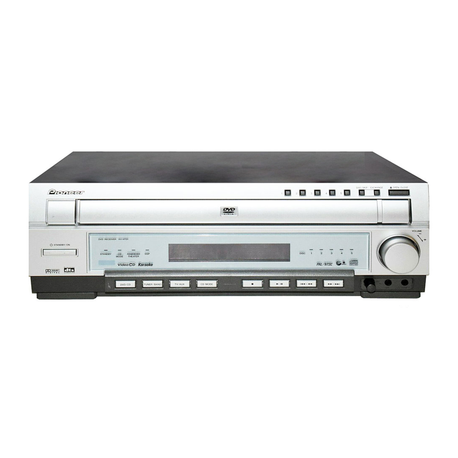
XV-HTD1 8. PANEL FACILITIES AND SPECIFICATIONS 8.1 PANEL FACILITIES Front Panel 0 OPEN/CLOSE DISC SKIP EXCHANGE VIDEO VOLUME DVD RECEIVER XV-HTD1 STANDBY/ON STANDBY ADVANCED DISC MODE THEATER 4 . 1 ¡ . ¢ DVD/CD TUNER/BAND TV/AUX CD MODE PHONES 12 11... -
Page 119: Rear Panel
XV-HTD1 Rear Panel AC IN power cord connection terminal SPEAKER terminals DIGITAL IN jack FRONT REAR AC INLET VOLTAGE SELECTOR SUB- SPEAKERS 240V CENTER WOOFER COAX 220- DIGITAL ANTENNA 230V 110- 127V VIDEO LOOP ANTENNA S-VIDEO UNBAL Ω VIDEO OUT jack... - Page 120 XV-HTD1 Remote Control Unit 15 ENTER 16 Cursor right Use for navigating menus and on- screen displays. TUNER STANDBY /BAND /AUX 17 MENU TEST TONE SURROUND MUTE CH LEVEL MODE TOP MENU 18 Cursor down Use for navigating menus and on- –...
-
Page 121: Specifications
XV-HTD1 8.2 SPECIFICATIONS Amplifier Section Power Supply Section Continuous power output (RMS) Power Requirements Front ........... 80 W, per channel European model ....AC 220-230 V, 50/60 Hz (1 kHz, 10 % T.H.D., 8 Ω) UK model ........ AC 230 V, 50/60 Hz Rear ...........