Table of Contents
Advertisement
Advertisement
Table of Contents

Related Manuals for Electrolux FLE120


Summary of Contents for Electrolux FLE120
-
Page 1: Service Manual
Service Manual FLE120 – FLE220 471 1553-11... -
Page 2: Table Of Contents
Machine description – safety rules Data Description of principal components Summary Programmes Carde programming Periodic maintenance Service- instruc- Operational sequences – trouble shooting tions Automatic unit Voltage control Timer Reverser Contactor Level control Thermostat Unbalance cutout Included Door & safety locking device units and Motor –... -
Page 3: Programmes
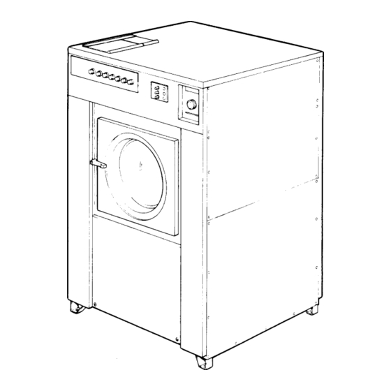
Service Manual 1. Machine description The machines referred to in this book have drum volumes of 120 and 220 litres and are high speed spin washing machines with flexible programmes. They are intended for installation in hotels, laundries, industry, hospitals, small institutions etc. The machines differ in size and capacity. - Page 4 Service Manual 1. Machine description Safety provisions • The machine is designed for water washing only. • The machine must not be used by children. • Installation and servicing must be carried out by qualified personnel. • The machine door safety locking device should be in working order and must not be by-passed under any circumstances.
- Page 5 Service 2. Data Manual FLE/FLE MP 120 l 220 l Dry weight capacity for filling factor 1:13 9.0 kg 17 kg for filling factor 1:10 12 kg 22 kg Drum volume 120 l 220 l diameter 620 mm 750 mm depth 412 mm 500 mm...
- Page 6 Service 2. Data Manual Voltage Element Total Fuse Connection cable output output Area mm Electric heating, 120 litres 220 V, 3AC 50 Hz 12,6 4 x 6 380 V, 3NAC 50 Hz 12,6 5 x 4 415 - 440 V, 3NAC 50 Hz 12,6 5 x 2,5 208 - 240 V, 3AC 60 Hz...
- Page 7 Service Manual 2. Data FLE MP FC (machine with frequency control) 120 l 220 l Dry weight capacity for filling factor 1:13 9.0 kg 17 kg for filling factor 1:10 12 kg 22 kg Drum volume 120 l 220 l diameter 620 mm 750 mm...
-
Page 8: Automatic Unit
Service Manual 3. Description of principal components The machine is a free-swinging model i.e. the outer drum and motor bridge and suspended in the machine chassis via a spring suspension with a strong spring in each corner of the machine. Each spring has a shock absorber which dampens the movement of the machine. - Page 9 Service Manual 4. Programmes The following is a description of the test card supplied with the machine. The basic procedure for programming (punching) cards is described in chapter "5. Card Programming". Function description of the card's 16 tracks A Detergent, compartment 1 B Heating, index B on the thermostat C Detergent, compartment 2 D Heating, index C on the thermostat...
- Page 10 Service Manual 4. Programmes Programme Track Removed Traclks on card stage A B C D E F G H I J K L M N O P Q x x ... x x . . Prewash O "Cold water"...
- Page 11 Service Manual 4. Programmes Prewash Prewash lasts for 4 minutes (track numbers 0 to 7). It starts with cold water to high level, detergent dispensing compartment 1 and heating until thermostat value selected on dial B is reached (peg number 0 in tracks A, B, N and O removed).
- Page 12 Service Manual 4. Programmes Rinses 1 to 3 Rinses 1-3 last for 4,5 minutes and are identical. Rinse 1 is described here. The rinse starts with cold water inflow until high water level is reached (peg 26 in track N and O removed). The automatic card device stops advancing the programmed card at peg 26 until the water level is reached.
-
Page 13: Timer
Service Manual 5. Card Programming Machines with the card programming facility have an automatic card device which reads a programmed card. The machines are intended for cards with 12, 16 or 24 tracks. Each track consists of a number of pegs which actuate the automatic card device's inbuilt sensors thus controlling the different stages of the washing process. - Page 14 Service Manual 5. Card Programming • During water inlet the timer will hold. It will restart when the level switch opens to indicate that the water level in the drum has been reached. • Hot and/or cold water may be programmed "Inlet". •...
- Page 15 Service Manual 11. Periodic maintenance The following steps should be taken to maintain optimum safety and performance of the machine and to prevent breakdowns. The timing should be adapted to the usage of the machine. Daily • Chek door and safety locking device. –...
-
Page 16: Reverser
Service 9108 Manual 12. Function Sequences Type Edition Page General, From machine No. 91/5501- (120 l machine) 91/5875- (220 l machine) To facilitate in faults tracing in the electrical system, the circuit diagram is broken down into a number of sequences, as follows: •... - Page 17 Service 9108 Manual 12. Function Sequences Type Edition Page Power supply and start The door must be closed (closing switch S3 (6)) and locked (switch S4 (8)) before power is supplied to machine. Turning programmer knob from 0 to I closes switch S30 (7).
- Page 18 Service 9108 Manual 12. Function Sequences Type Edition Page (1) F1 Fuse X20:6 (2) S2 Emergency stop (3) S1 ON/OFF switch (4) K54 Relay, start X3:7 X24:7 (5) F2 Overheat protection X24:9 X3:9 X8:1 (6) S3 Switch, door X8:2 (7) S30 Switch, programmer X8:5 (8) S4 Switch, door lock X8:6...
- Page 19 Service 9108 Manual 12. Function Sequences Type Edition Page Restart Use row M, stop (3) on the program card, to stop the program sequence either to dispense detergent or when the wash is done. When row M (3) has been programmed, the programmer switch changes from position 2-3 to 1-3.
- Page 20 Service 9108 Manual 12. Function Sequences Type Edition Page B : Power supply: see ''Power supply and start '' diagram X8:5 (1) S4 Switch, door lock X8:6 (2) K52 Relay, restart (3) Programmer, row M, stop power to wash fuctions (4) S32 Switch, restart (5) K52 Relay, restart (6) K52 Relay, restart...
-
Page 21: Door Lock
Service 9108 Manual 12. Function Sequences Type Edition Page Door lock When the door has been locked with the handle the microswitch S3 (6) is activated in the locking unit. Turning programmer knob to I closes switch S30 (7), delay unit D1 (11) is receiving power and door lock coil Y80 (12) locks the door. - Page 22 Service 9108 Manual 12. Function Sequences Type Edition Page (1) F1 Fuse X20:6 (2) S2 Emergency stop (3) S1 ON/OFF switch (4) K54 Relay, start X3:7 X24:7 (5) F2 Overheat protection, wash and distribution motor X24:9 X3:9 X8:1 (6) S3 Switch, door X8:2 (7) S30 Switch, programmer X8:5...
- Page 23 Service 9108 Manual 12. Function Sequences Type Edition Page Water filling The following conditions must be met for water valves Y14 (12), Y24 (13) or Y34 (14) to be energised: • Row M, stop (1) must not be programmed • The out-of-balance switch must not have tripped (breaks K53:51-52 (2) power supply) •...
- Page 24 Service 9108 Manual 12. Function Sequences Type Edition Page A C : Power supply: see ''Power supply and start'' diagram (1) Programmer, row M, stop (2) Relay K53, out-of-balance (3) Programmer, row K, drain (4) Relay K31, drain (5) Programmer, row N, high level (shown in normal position = low level) (6) Level control B1, low/high P<...
- Page 25 Service 9108 Manual 12. Function Sequences Type Edition Page Detergent The machine has three built-in detergent compartments controlled by three water valves. A total of five valves can also be controlled in an external supply unit via connector X19. The following conditions must be met to control the valves: •...
- Page 26 Service 9108 Manual 12. Function Sequences Type Edition Page : Power supply: see ”Power supply and start” sequence (1) Programmer, row M, stop (2) Relay K 53, out-of-balance (3) Programmer, row K, drain (4) Programmer, row A, detergent prewash V1 (5) Switch S37 , (detergent) (6) Programmer, row C,...
- Page 27 Service 9108 Manual 12. Function Sequences Type Edition Page Heating The following conditions must be met for relay K21/valve Y51 (11) to be energised: • The door must be closed and locked, and the programmer knob must be in position I (see ”Power supply and start” sequence) •...
- Page 28 Service 9108 Manual 12. Function Sequences Type Edition Page :Power supply: see ''Power supply and start'' sequence (1) Programmer, row M, stop (2) Relay K53, out-of-balance (3) Programmer, row K, drain (4) Relay K31, drain (5) Programmer, row N, high level (6) Level control B1, high/low level P<...
- Page 29 Service 9108 Manual 12. Function Sequences Type Edition Page Wash speed Relay K2 connects the wash speed windings on the wash motor. The following conditions must be met for relay coil K2 (7) to be energised: • The door must be closed and the programmer knob must be in position I (see ”Power supply and start”...
- Page 30 Service 9108 Manual 12. Function Sequences Type Edition Page A : Power supply: see ''Power supply and start'' sequence (1) Programmer, row M, stop X31:1 (2) Speed control B31 X31:2 (3) Relay K31, drain (4) Switch S33 (gentle action) (5) Reverser row 1 (6) Reverser row 2 (7) Relay coil K2, wash (8) Motor M22 Reverser...
- Page 31 Service 9108 Manual 12. Function Sequences Type Edition Page Cool-down The following conditions must be met for the cool-down valve Y11b (5) to be energised: • The door must be closed and locked, and the programmer knob must be in position I (see ”Power supply and start” sequence) •...
- Page 32 Service 9108 Manual 12. Function Sequences Type Edition Page A : Power supply: see ''Power supply and start'' sequence (1) Programmer, row M, stop (2) Relay K53, out-of-balance (3) Programmer, row K, drain (4) Programmer, row P, cool-down X9:7 (5) Valve Y11b, cool-down Y11b X9:9 D : Power supply: see ''Power supply and...
- Page 33 Service 9108 Manual 12. Function Sequences Type Edition Page Distribution speed Relay K3 connects the distribution speed windings on the wash motor. The following conditions must be met for relay coil K3 (13) to be energised: • The door must be closed and locked and the programmer knob must be in position I (see ”Power supply and start”...
- Page 34 Service 9108 Manual 12. Function Sequences Type Edition Page A : Power supply: see ''Power and start'' sequence (1) Programmer, row M, stop (2) Relay K53, out-of-balance (3) Programmer, row K, drain (4) Reverser, row 3 (5) Relay coil K31, drain X31:1 (6) Speed control B31 X31:2...
- Page 35 Service 9108 Manual 12. Function Sequences Page Type Edition Drain Relay K31 (5) controls the drain valve. The following conditions must be met for relay K31 to be energised: • The door must be closed and locked, and programmer knob must be in position I (see ”Power supply and start”...
- Page 36 Service 9108 Manual 12. Function Sequences Type Edition Page A : Power supply: see ''Power supply and start'' sequence (1) Programmer, row M, stop (2) Relay K53, out-of-balance (3) Programmer, row K, drain (4) Reverser, row 3b (5) Relay coil K31, drain (6) Switch S34 (drain) (7) Relay K31, drain...
- Page 37 Service 9108 Manual 12. Function Sequences Page Type Edition Extraction The section below and the diagram on the next page refer to 220 litre machines. In 120 litre machines, there is no clutch between the motors. Relays K9 (13), low extraction, and K10 (14), high extraction, control the connections to the extract motor windings.
- Page 38 Service 9108 Manual 12. Function Sequences Type Edition Page : Power supply: se ''Power supply and start'' sequence (1) Programmer, row M, stop X31:1 (2) Relay K53, out-of-balance (17) Speed control B31 (3) Programmer, row K, drain X31:3 X31:2 (4) Relay K31, drain X5:7 (18) Relay coil K31 Drain (5) Programmer, row H, spin...
- Page 39 Service 9108 Manual 12. Function Sequences Page Type Edition Out-of-balance This acts as a safeguard against excessive stress during the extraction. If the wash is unevenly distributed in the drum, the extraction stops, the wash is redistributed and the extraction starts again. This takes place automatically as follows: •...
- Page 40 Service 9108 Manual 12. Function Sequences Type Edition Page : Per supply: see ''Power supply and start'' sequence (1) Programmer, row M, stop (18) Relay K53 out-of- (2) Relay K31, drain balance (3) Out-of-balancce (19) Programmer, row K switch S9 drain (20) Reverser, row 3b (4) Relay K53, out-of-balance...
- Page 41 Service 9108 Manual 12. Function Sequences Page Type Edition Programmer advance The programmer stops at three stages in the wash cycle: during water filling, heating and if the out-of-balance switch trips. The following general conditions must be met for the programmer to start: •...
- Page 42 Service 9108 Manual 12. Function Sequences Type Edition Page : Power supply: see ''Power supply and start'' sequence (1) Programmer, row M, stop (2) Relay K53, out-of-balance (3) Programmer, row K, drain (4) Relay K31, drain (5) Programmer, row N, high level P<...
- Page 43 Service Manual 21. Automatic unit Machine with card programmer Switch ON. Switch acts as main switch for Fig. operating circuit. Switch RESTART. Switch restarts programme after ''programme stop'' and stops the advance of the buzzer. Swtich GENTLE ACTION, provides gentle action during wash.
- Page 44 Service Manual 21. Automatic unit Machine with frequency control Circuit breakers, motor control F12, F13 Conventional fuses 2213 Fig. Rotation guard for sensing that the drum has stopped before the door can be opened. This guard also indicates that the drum is actually rotating when the motor is operating.
- Page 45 Service Manual 23. Timer Description The automatic card device controls machine functions such as filling of water, drain, spin etc. The automatic card device has a row of microswitches (16) which sense the absence of pegs in the tracks on a programmed card.
- Page 46 Service Manual 23. Timer If the syncronised motor receives power but the motor is not running: – Remove the clamp which holds the motor and check that the output shaft of the motor revolves. (A fully synchronous motor can only rotate in one direction.
- Page 47 Service Manual 23. Programmer Description The programmer is electronic and is made up of two circuit boards, the control board with microprocessors and program memory, and the relay board with relays and interference suppression circuits. The programmer has the following outputs and inputs: •...
- Page 48 Service Manual 23. Programmer Repair Instructions A faulty electronic unit must be replaced, not repaired. Removing the circuit board • Unplug the board connectors and the tube to the level detector (see diagram below). NOTE: Marking on chip facing • Unscrew the 6 screws that secure the board. right way •...
- Page 49 Service Manual 23. Programmer Installing the circuit board Installing the ribbon cable • Plug in the connectors from the keyswitch and the ribbon cable. Note that the ribbon cable must be folded as shown in order to be plugged in the right way round.
- Page 50 Service Manual 23. Programmer Control transrormer On the primary side of the control transformer there are four terminals for 208, 220, 240 and 480 volt, and a neutral terminal. There are two secondary windings, one of which has a centre tap. The secondary voltages are 11-14 volt and 2 x 12-16 volt.
- Page 51 Service Manual 24. Reverser Description The revering and gentle action of the machine are controlled by the reverser. This contains a reversing cylinder with permanent cams which actuate the making and breaking contacts. The reversing cylinder is driven by a synchronised motor which rotates once in 3 minutes.
-
Page 52: Contactor
Service Manual 25. Contactor Data The contactor can handle a nominal voltage of +10%- 15%. Description The contactor consists of: • Housing in two halves with fixed, make and break, contacts. The halves are secured by spring brackets. • Movable contact bridge with movable contacts. •... - Page 53 Service Manual 25. Contactor Repair instructions The contactor fails to make or break • Check that the operating coil is energised. If this is the case, take measurements at the coil to check for a break. If a break has occurred, replace the coil as follows.
- Page 54 Service Manual 25. Relay Description Each relay consists of: • A casing in two halves, containing six normally- open and/or normally-closed contacts. The two halves are held together by spring clips. • A moving contact carrier containing moving contacts. • A soleniod, with coil and core. •...
- Page 55 Service Manual 25. Relay Relay repairs The relay does not open or close • Check that the coil is energised. If so, check its continuity. If the coil is open-circuited, replace it as follows: • Remove the auxiliary top contact block as described below under Replacement of Auxiliary Contact Block.
-
Page 56: Level Control
Service Manual 26. Level control Description The level control is a pressure guard which controls different pressures, i.e. water levels, independent of each other. The level control has two filling levels and High a third level which blocks the spin cycle so that it level level cannot start while there is water in the drum. - Page 57 Service Manual 26. Level control The machine does not fill with water • Check that the nipple on the underside of the level control is not blocked. A blockage can be caused by residual pressure below the level control's membrane indicating incorrectly that a level has been reached.
- Page 58 Service Manual 26. Level Detection Calibrating the level detector The level detector is at the left-hand end of the circuit board. Both zero level and mid position must be calibrated. Potentiometers P2 and P3 are used for these adjustments. IMPORTANT Do not adjust potentiometer P4.
- Page 59 Service Manual 26. Level Detection Setting the water level This is the procedure for determing how many "units" are needed to reach a given water level in the drum (so that this value can be entered in the wash program): •...
-
Page 60: Thermostat
Service Manual 27. Thermostat Data Area from – to approx 3°C Max temperature for bulb 150°C Description The thermostat checks the temperature during the course of the programme. The relays of the heating element are actuated by making and breaking contacts. -
Page 61: Unbalance Cutout
Service Manual 28. Unbalance cutout Description The unbalance cutout is a safety device. This prevents the machine from being damaged during spinning as a result of uneven distribution of the washing. This unbalance cutout consists of microswitches and an operating arm installaed in the automatic unit, together with a circular sensor which is installed in the counterweight of the machine. -
Page 62: Unbalance Cutout
Service Manual 28. Unbalance cutout Repair instructions Checking the adjustment of the unbalance cutout • When the machine is empty, check that the operating arm of the unbalance cutout is situated 5 mm under the centre of the sensor. If necessary, adjust by –... - Page 63 Service Manual 29. Door and safety locking device Description up to machine No. -91/5500 (120 l machine) -91/5874 (220 l machine) The machine safety locking device is a safety system Fig. A1 solenoid which prevents personal injury through the following Microswitch precautions.
-
Page 64: Door And Safety Locking Device
Service Manual 29. Door and safety locking device Description From machine No. 91/5501– (120 l machine) 91/5875– (220 l machine) The door safety locking device consists of the following main parts: Fig. • Locking unit. The door locking unit is placed behind the front plate and under the detergent box. - Page 65 Service Manual 29. Door and safety locking device Function Fig. When the door has been locked by the door handle, the locking arm is turned and activating the microswitch S3 in the locking unit. When the programmer knob is turned to position I, switch S30 is closed, the delay unit receives voltage and the coil is locking the door.
-
Page 66: Fault Finding
Service Manual 29. Door and safety locking device Fault finding The coil does not lock the door when programmer knob is turned to I. • Check that lamp in the red push button is lightning. If not, check that the emergency opening is not activated. - Page 67 Service Manual 29. Door and safety locking device Description FLE MP FC (Machines with frequency control) The machine door lock is made up of the following main components: Fig. • Lock unit, located behind the front panel under the detergent compartment.
- Page 68 Service Manual 29. Door and safety locking device Function If the machine has not been energised within the last three minutes, the door will remain unlocked. When the machine is energised the door will be locked if a program is activated or if the drum is rotating. Upon completion of a program the door will be unlocked automatically as soon as the drum has stopped rotating.
- Page 69 Service Manual 29. Door and safety locking device Fault location Door does not unlock Conditions: wash program ended and drum at a standstill Measure the voltage between the following points: 1. X93:2 - X93:3 Should be 0 V DC. If the voltage is 220 V AC, check the rotation guard.
-
Page 70: Speed Guard
Service 30. Motor Manual Description FLE and FLE MP Both motors, one for wash and distribution and one for extraction, are installed on the same Fig. motor bridge. The motors drive the drum and are mechanically connected to each other by V-belts. - Page 71 Service 30. Motor Manual FLE MP FC (machines with frequency control) In machines with frequency control the same motor is used for wash speed, distribution speed and extraction. The motor is located on a motor mounting plate, and drives the drum via a belt. The tension of this drive belt can be altered by moving the entire motor mounting plate thanks to the mounting slots on one side.
-
Page 72: Program Start
Service Manual 30. Motor Program start The following conditions must be fullfilled before the motor can start: • Motor not overloaded. • Door shut. • Go-ahead signal from programmer. When the door is locked relay K71 is activated feeding power to the electronic control unit and the motor is allowed to start. - Page 73 Service 30. Motor Manual Repair instructions Overheated motor, motor not running • Wait till motor has cooled down. Motor guards are automatically reset after 30 minutes. Restart. • Possible cause of motor gurads releasing FLE/FLE MP repeatedly: short circuiting. In both cases the motor should be replaced.
- Page 74 Service 30. Motor Manual FLE/FLE MP FC (Machines with frequency control) Fig. Loosen the screws holding the motor mounting plate on the motor side. Lower the motor mounting plate until the correct belt tension is obtained, as shown in Fig. 5. Secure the motor mounting plate in place. To adjust the clutch (FLE/FLE MP only) - 0,0 For a new clutch the airgap between stator and rotor should be 0.3 (-0.0 /...
- Page 75 Service 30. Motor Manual In two cases the machine will be halted without indication: • Overvoltage in feed. • Motor and/or motor control overheated. Motor does not operate when it should • Check the voltage feed to the motor control unit by: - Disconnecting XM4 (quick connector) - Using a voltmeter (AC) to measure between pins XM4:1-2.
- Page 76 Service Manual 31. Speed Guard FLE/FLE MP Description The purpose of the speed guard is to protect the Fig. wash motor during extraction. On the motor output shaft there is a polarised magnet element (wash motor on 120 litres; spin motor on 220 litres) which is sensed by the speed guard.
-
Page 77: Speed Guard
Service 31. Speed Guard Manual FLE MP FC (Machines with frequency controlled motor) Description The rotation guard checks that the machine is completely at a standstill before the door can be opened. When the drum has been at a standstill for approx. two seconds Fig. -
Page 78: Inlet Valve, Water
Service Manual 34. Inlet valve, water Data Max capacity, unrestrict., outlet 12 l/min inlet 20 l/min Coil Working range, water pressure 0,3-10 bar Number of sections 1, 2, 3 or 4 Metal plate Description Pressure The valve is operated electromagnetically and has a spring rubber diaphragm as a closing and opening element. - Page 79 Service Manual 34. Inlet valve, water Repair instructions Scale deposits can clog the hole in the diaphragm and disturb the operation of the valve. It is thus advisable that the valve be taken apart and cleaned at regular intervals, depending on operating conditions and the degree of contamination of the water.
- Page 80 Service Manual 34. Water inlet valve Data Maximum capacity, fully open outlet 160 l/min inlet 20 l/min Coil Working range, water pressure 0,5-10 bar Number of outlets 1, 2, 3 or 4 Description Plunger The valve is solenoid-operated, having a rubber membrane as the sealing element.
- Page 81 Service Manual 34. Water inlet valve Repair instructions Lime deposits can block the holes in the valve membrane and interfere with correct operation. It is therefore recommended that the valve be dismantled and cleaned at regular intervals, depending on operating conditions and the amount of dirt in the water.
- Page 82 Service Manual 34. Inlet valve, water Data Capacity at 300 kPa 300 l/min Armature Coil Operating limits 40-1000 kPa Description The valve is electromagnetically operated and has a rubber diaphragm as its opening and closing element. The valve utilises the water pressure when opening and closing.
- Page 83 Service Manual 34. Inlet valve, water Repair instruction Valve operation gradually gets worse Needle Hot water with high lime content may cause scale deposits in the balancing nozzle of the valve. Clean the nozzle as follows: • Shut off the water. •...
-
Page 84: Inlet Valve, Steam
Service Manual 35. Inlet valve, steam Description The steam valve is operated electromagnetically and has a plunger with a valve head as opening and closing element. The valve utilises the steam pressure for opening and closing. In a closed position the electromagnet is unactivated and the releif hole in the centre of the plunger is closed by the armature through its pressure spring. -
Page 85: Drain Valve
Service Manual 38. Drain valve Description The drain valve is a motor-operated diaphragm valve which ensures rapid machine emptying by its opening on a large cross-sectional surface area. Its design is self-clearing, which eliminates the need for fluff filters. The main components are: •... - Page 86 Service Manual 38. Drain valve Repair instructions Deposits of scale in the diaphragm may prevent the valve from closing or opening correctly. The valve should be cleaned at specific intervals which depend on the operating conditions and the quality of the water. The valve fails to open or close correctly •...
-
Page 87: Detergent Compartment
Service Manual 39. Detergent compartment Description The detergent container has three compartments • compartment 1 for detergent (prewash) • compartment 2 for detergent (main wash) • compartment 3 for conditioner The container is fitted with nozzles coupled to the inlet valves. These ensures that the detergent dissolves properly in the water, as well as flushing the container clean. -
Page 88: Heating
Service Manual 40. Heating Data Y – connection for 380V Rated output See section 2. Data Connections Y – connection at 380V D – connection at 220V Description The three elements are situated at the bottom of the space between the inner and outer drums. They are actuated by a heat relay which in turn is controlled by the programme unit and thermostat. - Page 89 Service Manual 40. Heating Element replacement • Remove the cover from the inner drum. • Removed nuts, washers and clamps through the cover opening in the inner drum. • Undo the nut on the middle screw of the element and turn the screw 1/4 of a turn. The counterweight on the inside is now in a position to permit the element to be withdrawn.
-
Page 90: Frame
Service Manual 43. Frame Description The frame is constructed on the free-swinging principle, i.e. the washing drum is freely and resiliently suspended in the fixed frame. The entire frame is constructed of bent sheet metal and aluminium sections forming a stable and torsionally rigid structure. -
Page 91: Time Relay
Service Manual 49. Time Relay Data Motor 220V 50/60Hz Contacts, making capacity 6 (10) A 250V Dial for setting time Scale (breaking capacity) Description The automatic unit has a time relay for drain which prevents the spin from starting too early – the water must have drained.