
Related Manuals for Samsung M959R


Summary of Contents for Samsung M959R
-
Page 1: Table Of Contents
MICROWAVE OVEN M959R SERVICE Manual MICROWAVE OVEN CONTENTS 1. Precaution 2. Specifications 3. Operating Instructions 4. Disassembly and Reassembly Auto 5. Alignment and Adjustments Auto 6. Troubleshooting Auto 10s. 1min 10min 1 min + 7. Exploded Views and Parts List 8. - Page 2 (e) A Microwave leakage check to verify compliance with the Federal performance standard should be performed on each oven prior to release to the owner. Samsung Electronics...
-
Page 3: Precaution
CENTRAL SERVICE CENTER 16. Always connect a test instrument's ground lead to the instrument chassis ground before 10. Service technicians should remove their connecting the positive lead; always remove watches while repairing an MWO. the instrument's ground lead last. Samsung Electronics... - Page 4 (Use a screwdriver.) 3. High voltage is maintained within specified limits by close-tolerance, safety-related components and adjustments. If the high voltage exceeds the specified limits, check each of the special components. Fig. 1-1. Discharging the High Voltage Capacitor Samsung Electronics...
-
Page 5: Specifications
COOLING FAN MOTOR 810W 28 sec 2 sec OUTSIDE DIMENSIONS 517(W) x 297(H) x 395(D) 100% 900W 30 sec 0 sec 2-2 Comparison Chart MODEL M959R FEATURE AUTO REHEAT AUTO COOK POWER LEVEL TIME SETTING AND WEIGHT AUTO DEFROST DEODORIZATION Samsung Electronics... -
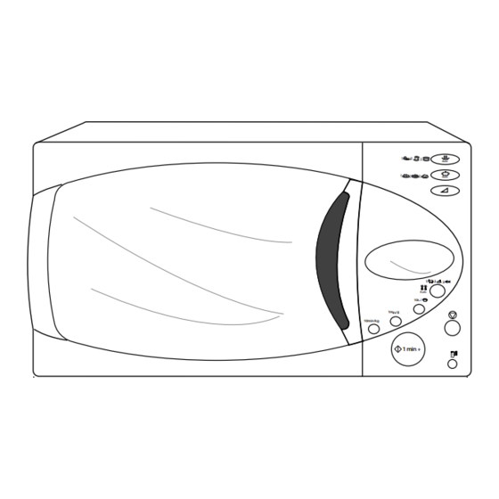
Page 6: Operating Instructions
Door Light Safety Interlock Holes Ventilation Holes Auto Auto Display Control Panel Auto 10s. 1min 10min 1 min + M959 Glass Plate Roller Ring Door Latches Coupler Auto Auto Auto 10s. 1min 10min 1 min + 517mm 395mm Samsung Electronics... -
Page 7: Disassembly And Reassembly
VOLTAGE TRANSFORMER secondary and filament terminals. It is extremely dangerous to work on or near these circuits with the oven energized. Screws H. V. Trans DO NOT measure the voltage in the high voltage circuit including filament voltage of magnetron. Samsung Electronics... -
Page 8: Replacement Of Door Assembly
1. Insertion depth of the thin metal plate should be 0.5mm or less. 4-3-4 Removal of Key Door & Spring Remove pin hinge from Door "E" Door "E" Detach spring from Door "E" and key door. Key Door Spring Samsung Electronics... -
Page 9: Replacement Of Fuse/Drive Motor
Base Plate Drive Motor Cover 8. Connect all the leads to the drive motor. 9. Screw the deive motor cover to the base plate with a screw driver. 10. Remount the coupler in the correct position. Samsung Electronics... - Page 10 3. Lift up the control circuit board from the Ass'y Connector control box. 4. When reconnecting the FPC connector, make sure that the holes on the connector are properly screw engaged with the hooks on the Plastic Fastener. Samsung Electronics...
-
Page 11: Alignment And Adjustments
3. Before touching any oven components or wiring, always unplug the oven from its power source and discharge the high voltage capacitor. 5-1 High Voltage Transformer 1. Remove connectors from the transformer terminals Filament Terminals and check continuity. 2. Normal resistance readings are as follows: MODEL M959R Secondary Approx. 130Ω Filament Approx.0Ω Primary Approx.1.700Ω... -
Page 12: High Voltage Capacitor
∞ Primary switch 5. Confirm that the gap between the switch ∞ Monitor switch (COM-NC) housing and the switch actuator is no more than ∞ Monitor switch (COM-NO) 0.5mm when door is closed. ∞ Door Sensing S/W Samsung Electronics... - Page 13 5. After heating for 2 minutes, measure the water temperature in each beaker. 6. Microwave heat distribution rate can be calculated as follows: Minimum Beaker Temperature Rise Heat Distribution = X 100(%) Maximum Temperature Rise The result should exceed 65%. Cooking Tray Samsung Electronics...
-
Page 14: Procedure For Measurement Of Microwave Energy Leakage
; CENTRAL SERVICE CENTER 5-13-2 At least once a year have the microwave energy survey meter checked for accuracy by its manufacturer. Samsung Electronics... -
Page 15: Troubleshooting
H.V.Transformer component test procedure and replace if it is H.V.Capacitor defective. H.V.Diode, H.V.Fuse Magnetron 4. Open or loose wiring of power relay 5. Defective primary latch switch 6. Defective power relay or Ass'y PCB Replace PCB main. Samsung Electronics... - Page 16 Use plastic wrap or cover with a lid. Stir once or twice while cooking foods such as soup, cocoa, or milk. Noise from the turntable motor Noise may result from the motor. Replace turntable motor. when it starts to operate. Samsung Electronics...
-
Page 17: Exploded Views And Parts List
7. Exploded Views and Parts List 7-1 Exploded Views Samsung Electronics... -
Page 18: Main Parts List
THERMOSTAT;PW2N-52JC 100/60 250V/7.5A H M 24 DE71-60382A COVER-CEILING;MICASHEET T0.5 70 133 M 25 ASSY DOOR;M959/AMF WHT BASIC M 26 ASSY CONTROL-BOX;230V50HZ M959R WHT RUSSIA M 27 DE74-20015B TRAY-COOKING;GLASS T6.0 PI318 1050G MW5630T M 28 DE92-90189D ASSY-GUIDE ROLLER;D19 STD M 29 DE67-60075A COUPLER;PPS 7G BRN M97G45... -
Page 19: Door Parts List
BUTTON-SELECT-E;ABS(HR0370U) WHT 2G M959 C 13 DE61-70126A SPRING-KEY;0.8 36 6 BLUING C 14 DE66-20173E BUTTON-START;ABS(HR0370U) 7G WHT M959 C 15 DE93-30406J ASSY CONTROL-PANEL;M959R/BWT WHT 7-5 Body Latch Parts List Ref. No Parts No. Description / Specification Q'ty Remarks DE66-40021A LATCH-BODY;POM(F20-02) 50GR RE-330 3405-000178 SWITCH-MICRO;250V,15A,200gf,SPST-NO... -
Page 20: Standard Parts List
DE60-10082H SCREW-A;2S-4X12,TOOTHED BD-LAT DE60-10082H SCREW-A;2S-4X12,TOOTHED CN-BOX DE60-10082H SCREW-A;2S-4X12,TOOTHED CV/AIR DE60-10082H SCREW-A;2S-4X12,TOOTHED MO/FAN DE60-10098A SCREW-ASSY TAP TITE;PH,TC,M4X8,SWRCH18A,ZPC2,GLD,W CV-TCO DE60-10098A SCREW-ASSY TAP TITE;PH,TC,M4X8,SWRCH18A,ZPC2,GLD,W M/GEAR DE60-10045A SCREW-TAP PH;PH,M3,L6,FEFZY DE60-10066A SCREW-TAP TH;TH,M4,L8,FEFZY,2-SLOT H/DOOR DE60-10012A SCREW-TAP TITE;TH,+,3,M4,L10,SWR10,ZPC2,TOOTH B/D-MO DE60-10098A SCREW-ASSY TAP TITE;PH,TC,M4X8,SWRCH18A,ZPC2,GLD,W B/HVC Samsung Electronics... - Page 21 8. P.C.B Diagrams 8-1 P.C.B Diagrams Samsung Electronics...
- Page 22 R09,R14,R16 2001-000904 R-CARBON;620ohm,5%,1/8W,AA,TP,1.8x3.2mm 2202-000780 C-CERAMIC,MLC-AXIAL”;100nF,+80-20%,50V,Y5V,TP,3.5x1 C05~C08 2401-000247 C-AL;100uF,20%,10V,GP,-,6.3x11mm,5m 2401-000876 C-AL;220uF,20%,50V,GP,TP,13x20mm,5m 2401-000914 C-AL;22uF,20%,16V,-,TP,5x11,5mm 2401-001362 C-AL;470uF,20%,16V,GP,-,10x12.5mm,5 2802-000161 RESONATOR-CERAMIC;4MHz,0.5%,TP,10.0x5.0x7.5mm XTL1 3404-000282 SWITCH-TACT;12Vdc,50mA,120+-30gf,6.2x3.6mm SW01~SW10 3711-000203 CONNECTOR-HEADER;1WALL,3P,1R,3.96mm,ANGLE,SN CN01 3711-000240 CONNECTOR-HEADER;1WALL,4P,1R,3.96mm,STRAIGHT,SN CN02 3711-000881 CONNECTOR-HEADER;BOX,3P,1R,2.5mm,STRAIGHT,SN CN03 DE13-20009A IC;KA7533,DIP IC03 DE39-60001A WIRE-SO COPPER;PI0.6,SN,T,52MM,TAPING_WIRE J01~J10 DE60-60012A PIN-EYELET;ID2.1,OD2.5,L3.0,SN,BSP,T0.25 Samsung Electronics...
-
Page 23: Schematic Diagrams
POWER 3. LAMP : ON SWITCH SYMBOL COLOR RELAY RELAY RELAY L.V.T : P.C.B PATTERN BROWN BLUE : P.C.B IN/OUT ORANGE POINT ASSY MAIN P.C.B WHITE BLACK YELLOW MONITOR PRIMARY DOOR GREEN SWITCH LATCH SENSING YELLOW/GREEN SWITCH SWITCH Samsung Electronics...