
Related Manuals for Nikon SB-500


Summary of Contents for Nikon SB-500
- Page 1 SB - 500 Speedlight User's Manual (with Warranty) Nikon Manual Viewer 2 Use the Nikon Manual Viewer 2 app to view manuals anytime, anywhere on your smartphone or tablet.
-
Page 2: About The Sb-500 And This User's Manual
About the SB-500 and This User’s Manual Thank you for purchasing the Nikon Speedlight SB-500. To get the most out of your Speedlight, please read this user’s manual thoroughly before use. How to find what you are looking for i Table of contents... - Page 3 Included items Check that all items listed below are included with the SB-500. If any items are missing, inform the store where the SB-500 was purchased or the seller immediately. ❑ Speedlight Stand AS-23 ❑ User’s manual (this manual) ❑ Soft Case SS-DC2 ❑...
- Page 4 (except D1 series and D100), F6, CLS-compatible COOLPIX cameras (0G-1) • The SB-500 can be used as a master flash unit only when mounted on the D810 or D750. • The SB-500’s LED light is designed for photography and movie recording.
- Page 5 Speedlight malfunctions or mistakes. Includes information or tips to make Speedlight use easier. Reference to other pages in this manual Tips on identifying CPU NIKKOR lenses CPU lenses have CPU contacts. CPU contacts • The SB-500 cannot be used with IX-Nikkor lenses.
- Page 6 About the SB-500 and This User’s Manual Terminology Nikon Creative Lighting System ( CLS): a lighting system that enables flash photography functions listed below with improved communication between Nikon Speedlights and cameras i-TTL flash control/Advanced Wireless Lighting/Modeling flash/ FV lock/Flash (LED Light) Color Information Communication/...
- Page 7 i-TTL balanced fill-flash: i-TTL flash control type in which flash output level is adjusted to well-balanced exposure of the main subject and background Standard i-TTL flash: i-TTL flash control type in which flash output level is adjusted to the correct exposure of the main subject regardless of background brightness Manual flash control: flash control mode in which the flash...
-
Page 8: Flash Photography
Q&A Index You can search for specific explanations according to objective. Flash photography 1 Using the SB-500 mounted on a camera’s accessory shoe Question Key phrase Which flash control mode can I take Flash control modes pictures with? How can I take pictures in the simplest... - Page 9 Using the wireless SB-500 Question Key phrase How do I take pictures using multiple flash Advanced Wireless E-2, units? Lighting How do I take pictures with the SB-500 COOLPIX cameras and a COOLPIX camera compatible with compatible with CLS wireless multiple flash-unit photography?
-
Page 10: Table Of Contents
Table of Contents Preparation About the SB-500 and This User’s Manual ......A-2 Q&A Index ............... A-8 For Your Safety .............. A-13 Check before Use ............A-18 Operation Speedlight Parts ..............B-1 Notes on Continuous Use ..........B-7 Basic Operations ..............B-9 Flash Control Modes i-TTL Flash Control ............ - Page 11 Functions Bounce Flash Operation ............ F-2 Flash Photography Support Functions ........ F-7 • Test firing • Modeling flash • Standby function • Thermal cut-out Functions to Be Set on the Camera ......... F-12 • Auto FP High-speed sync • Flash value lock (FV lock) •...
- Page 12 Guide Number, Aperture and Flash-to-subject Distance ..H-5 Tips on Speedlight Care ........... H-6 Notes on Batteries............H-8 Updating Firmware ............H-10 Optional Accessories ............H-11 Specifications ..............H-13 Index ................H-21 Warranty Terms - Nikon Worldwide Service Warranty ..H-27 A-12...
-
Page 13: For Your Safety
For Your Safety To prevent damage to your Nikon product or injury to yourself or others, read the following safety precautions in their entirety before using this equipment. Keep these safety instructions where all those who use the product will read them. - Page 14 For Your Safety Keep dry. Do not immerse in or expose to water or rain. Failure to observe this precaution could result in fire or electric shock. Do not handle with wet hands. Failure to observe this precaution could result in electric shock. Do not use in the presence of flammable gas or dust.
- Page 15 • Insert batteries in the correct orientation. • Batteries may become hot if the flash is fired multiple times in quick succession. When removing the batteries, take precaution to avoid burns. • Do not short or disassemble batteries or attempt to remove or otherwise damage the battery insulation or casing.
- Page 16 For Your Safety Observe caution when using the flash • Using a flash in close contact with the skin or other objects could cause burns. • Using the flash close to subject’s eyes could cause temporary visual impairment. Stay at least 1 m (3.3 ft) from the subject when using the flash.
- Page 17 Notice for Customers in Canada CAN ICES-3 B / NMB-3 B Notice for customers in Europe This symbol indicates that electrical and electronic equipment is to be collected separately. The following apply only to users in European countries: • This product is designated for separate collection at an appropriate collection point.
-
Page 18: Check Before Use
“A collection of example photos” provides an overview of the SB-500’s flash photography capabilities with example images. To download the PDF file, access the link below and choose “Speedlights” from the “Digital SLR Cameras” category, then go to the “SB-500.” http://nikonimglib.com/manual/ A-18... - Page 19 Visit these sites to keep up to date with the latest product information, tips, answers to frequently-asked questions (FAQs) and general advice on digital imaging and photography. Additional information may be available from the Nikon representative in your area. See the URL below for contact information: http://imaging.nikon.com/...
-
Page 20: B Operation Speedlight Parts
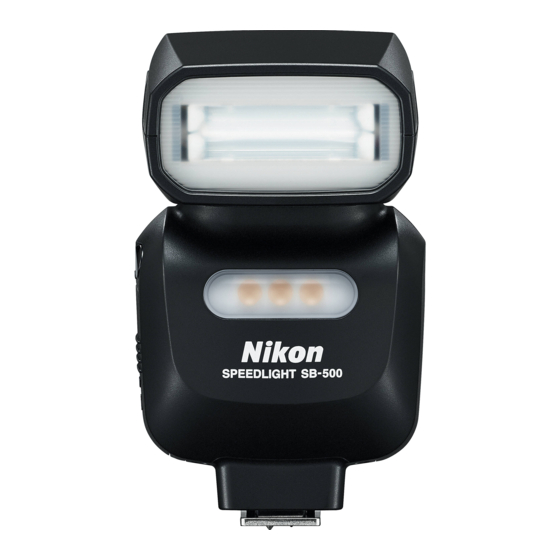
Operation Speedlight Parts... - Page 21 1 Flash head 2 LED light (0D-1) 3 Light sensor window for wireless remote flash (0E-7) 4 Battery chamber cover 5 Locking pin 6 Accessory shoe contacts 7 Mounting foot 8 Flash panel...
- Page 22 Speedlight Parts...
- Page 23 9 Flash head tilting angle scale (0F-3) 10 Flash head rotating angle scale (0F-3) 11 Flash-ready indicator (0B-14, E-10) 12 Mounting foot lock lever (0B-12)
- Page 24 Speedlight Parts...
- Page 25 13 LED button ( D-3) 17 Power switch : Press and hold down to • Rotate to turn power on turn the LED light on and off. and off. • Set the index to choose the : Press briefly to change LED function to be used.
-
Page 26: Notes On Continuous Use
Notes on Continuous Use Notes on continuous flash firing • To prevent the SB-500 from overheating, allow it to cool down for at least 10 minutes after the number of firings indicated below. Flash control mode Firing limit i-TTL flash control... - Page 27 Notes on LED light operation duration • The internal safety function automatically lowers the LED light output level by 1 level when the LED light is used for an extended period of time. (0F-11) • If the LED light is used for a longer period, the internal safety function turns the LED light off.
-
Page 28: Basic Operations
Basic Operations This section covers basic procedures in i-TTL flash control in combination with a CLS-compatible camera. STEP Inserting the batteries Slide the battery chamber cover open. Insert the batteries following the [+] and [−] marks. Close the battery chamber cover. - Page 29 Suitable batteries Replace both batteries at the same time using fresh batteries or fully-charged rechargeable batteries of the same brand from any of the following types. Do not mix old and new batteries or batteries of different types or makes. 1.5 V LR6 (AA-size) alkaline battery 1.2 V HR6 (AA-size) rechargeable Ni-MH battery •...
- Page 30 Refer to the following table to determine when to replace batteries with fresh ones or recharge batteries according to how long the flash- ready indicator takes to light up after turning the SB-500 on or flash firing. 1.5 V LR6 (AA-size) alkaline battery 20 sec.
- Page 31 “LOCK.” Cameras with auto pop-up flash units Turn the SB-500 on when it is mounted on a camera with a built-in, auto pop-up flash unit. When the SB-500 is turned off, the camera’s built-in flash may pop-up automatically and strike the SB-500. It is recommended to detach the SB-500 from the camera when not in use.
- Page 32 SB-500’s mounting foot from the camera’s accessory shoe. • If the SB-500’s mounting foot cannot be removed from the camera’s accessory shoe, turn the mounting foot lock lever 90° to the left again, and slide the SB-500 slowly out.
-
Page 33: Turning The Power On
Set the SB-500’s power switch to [ ]. • Mode indicator lamp [TTL] comes on. STEP Taking a picture Make sure that the flash- ready indicator on the SB-500 or in the camera’s viewfinder is on, and then shoot. B-14... -
Page 34: C Flash Control Modes
• To take pictures using the SB-500 set in i-TTL flash control, see “Basic Operations.” (0B-9) • Either the i-TTL balanced fill-flash or the standard i-TTL flash option is available depending on the camera settings. - Page 35 When insufficient flash output for correct exposure is indicated • When the flash-ready indicators on the SB-500 and in the camera’s viewfinder flash slowly for approximately 3 sec. after firing, underexposure due to insufficient flash output may have occurred.
-
Page 36: Manual Flash Control
Manual Flash Control When the SB-500 is mounted on a camera, manual setting of flash output level can be enabled by selecting [Manual] under [Optional flash] from the camera menu. • Monitor pre-flash and the indication of insufficient flash output for correct exposure are not available in manual flash control. -
Page 37: Dled Light Features Of Led Light
LED Light Features of LED Light The SB-500 is equipped with an LED light that has various features, as detailed below. Continuous light that enhances your photography In contrast to a flash light, the LED light is a continuous light source. You... - Page 38 • Use the provided Speedlight Stand AS-23 for stable positioning of the SB-500. Attach and detach the SB-500 to and from the AS-23 in the same way it is attached to/detached from the camera’s accessory shoe.
-
Page 39: Using The Led Light
Using the LED Light Turning the LED light on Set the SB-500’s power switch to [ ]. • Rotate the power switch while pressing the lock release. Press and hold the LED button until the LED light comes on. Turning the LED light off... - Page 40 Using the LED Light Changing the LED light output level Briefly press the LED button to change the LED light output level. • The LED light output level changes as shown in the diagram below. The output level is indicated by the LED light output level indicator lamps.
- Page 41 • LED light operation is manual only. The LED light does not synchronize with the camera shutter. • The LED light turns off when the SB-500 is in standby and does not turn on when the SB-500 comes on again.
-
Page 42: E Wireless Multiple Flash-Unit Photography
SB-500 Wireless Multiple Flash- unit Photography Setup The SB-500 is compatible with Advanced Wireless Lighting. • The SB-500 has to be mounted on the D810 or D750 to be used as a master flash unit. SB-500 wireless multiple flash-unit photography... - Page 43 • Up to 2 groups (A and B) of remote flash units can be set up. • Single or several remote flash units can be allocated for 1 group. • Channel 3 must be used when the SB-500 is used as a remote flash unit.
-
Page 44: Sb-500 Wireless Multiple Flash-Unit Photography Functions
SB-500 Wireless Multiple Flash-unit Photography Functions When used in When used in commander mode remote mode i-TTL flash control • i-TTL flash control • Flash control Manual flash control • Manual flash control • mode Non-TTL auto flash • Repeating flash* •... - Page 45 Notes on canceling the flash of the master flash unit When the master flash unit flash function is canceled and only the remote flash units fire, the master flash unit emits a number of weak light signals to trigger the remote flash units. This operation will normally not affect the correct exposure of the subject, although the exposure might be affected if the subject is close and a high ISO sensitivity has been set.
-
Page 46: Advanced Wireless Lighting
Advanced Wireless Lighting Using the SB-500 as a master flash unit Set the SB-500’s power switch to [ ]. Make settings with the camera. • Choose [Commander mode] under [Optional flash] from the camera menu and make settings. • For details, see the camera user’s manual. - Page 47 Using the SB-500 as a remote flash unit Set the power switch to [A] or [B] to correspond with the remote flash group selected on the master flash unit. • Rotate the power switch while pressing the lock release. • Set the remote flash channel to 3 on the master flash unit.
-
Page 48: Remote Flash Units
Remote Flash Units Remote flash unit setting • The standby function is canceled when remote mode is set. Make sure that there is sufficient battery power. Setting up the remote flash units • Position the remote flash units so that light from the master flash unit can reach the light sensor window for wireless remote flash of the remote flash units. - Page 49 • As a basic guide, the effective distance between the master and remote flash units is up to approximately 10 m (32 ft) in the forward-facing position, and approximately 7 m (22 ft) at both sides. These ranges vary slightly depending on ambient light. •...
- Page 50 • Take care not to let light from the remote flash units enter the camera lens. • Use the provided Speedlight Stand AS-23 for stable positioning of remote flash units. Attach and detach the SB-500 to and from the AS-23 in the same way it is attached to/detached from the camera’s accessory shoe.
- Page 51 Checking Status in Wireless Multiple Flash-unit Photography The flash-ready indicator on the SB-500 can be used to check the status during and after taking a picture in wireless multiple flash-unit photography. Checking flash operation using the flash-ready indicator Master flash...
-
Page 52: Checking Status In Wireless Multiple Flash-Unit Photography
Checking Status in Wireless Multiple Flash-unit Photography Master flash Remote flash Speedlight status unit unit Non-TTL auto flash control mode • is set on the master flash unit. Change the flash control mode to an operable flash control mode. The remote flash unit light sensor •... - Page 53 Functions This section explains the SB-500 functions that support flash photography and functions to be set on the camera. • For detailed information regarding camera functions and settings, refer to the camera user’s manual. Bounce flash operation (0F-2) Test firing...
-
Page 54: Bounce Flash Operation
Bounce Flash Operation Bounce flash is a photographic technique using light that is bounced off a ceiling or wall using a tilted or rotated flash head. This provides the effects listed below compared to those with direct light from a flash unit: •... - Page 55 Setting the flash head Tilt or rotate the flash head. • The flash head tilts up from 0° to 90° and rotates horizontally 180° to the left and right. • Set the flash head at a click stop at the angles shown.
- Page 56 Bounce Flash Operation Selecting flash head tilting/rotating angles and a reflecting surface • Good results are most easily achieved when the flash head is tilted up to use the ceiling as a reflecting surface. • Rotate the flash head horizontally to get the same effect when the camera is held in the vertical position.
- Page 57 Behind the camera White ceiling 1-2 m 90º Lightproof white paper...
-
Page 58: Adjust The Flash Head
Bounce Flash Operation Taking a picture with bounce flash Set the SB-500’s power switch to [ ]. Adjust the flash head and shoot. Exposure in bounce flash operation In bounce flash, there is some light loss compared with normal flash photography (with flash head adjusted to the forward-facing position). -
Page 59: Flash Photography Support Functions
LED light. Test firing Pressing the test firing button determines whether the SB-500 fires properly. • The flash output level during test firing varies depending on settings and flash control modes. -
Page 60: Standby Function
Flash Photography Support Functions Standby function If the SB-500 and camera are not used for a specified time, the standby function is automatically activated to conserve battery power. Standby activation depends on the functions being used. Connection with camera Power switch... -
Page 61: Thermal Cut-Out
• Select any function other than [OFF] • Press the camera shutter-release with the SB-500’s power switch. button halfway down. • Press the SB-500’s test firing button. • Turn the camera on. • Select any function other than [OFF] with the SB-500’s power switch. - Page 62 Flash Photography Support Functions Warning of flash-ready indicator Flashes once per sec. • Wait until the SB-500 cools down. • Operation can be resumed once the warning goes off. F-10...
- Page 63 LED light off. When this happens, allow the SB-500 to cool down for a while and then turn the power on again. The LED light will not automatically return to the same LED light output level it was at before turning off.
-
Page 64: Functions To Be Set On The Camera
FP high-speed sync, refer to “Specifications.” (0H-19) Flash value lock ( FV lock) The SB-500 sets the flash output to locked flash exposure. This maintains the subject’s illumination, even if the composition changes. • FV lock also functions in the Advanced Wireless Lighting. -
Page 65: Slow Sync
• Use of a tripod is recommended. Red-eye reduction The SB-500 fires 3 flashes at low output just before the picture is taken to reduce the red-eye effect caused by the flash light. Rear-curtain sync Rear-curtain sync flash creates the effect of a smooth stream of light behind the subject. -
Page 66: G For Use With Coolpix Cameras
P5000, E8800, E8700, E8400) • See the camera user’s manual as well. *1 Only the flash light can be used when the SB-500 is mounted on COOLPIX P7100 or P7000. Detach the SB-500 from the camera when using the LED light. - Page 67 Possible (A, P7800, Not possible Communication P7700 only) Possible (except P7800, Red-eye reduction Not possible P7700) Firmware update Possible (A only) Not possible *2 Flash control modes cannot be selected on the SB-500. The mode set on the camera automatically applies.
-
Page 68: Tips On Speedlight Care And Reference Information
Troubleshooting If the flash-ready indicator flashes slowly, or any trouble occurs, use the following chart to determine the cause of the problem before taking the Speedlight to a retailer or Nikon-authorized service representative for repair. Problems with the SB-500 Problem... - Page 69 • Set the SB-500’s power switch to any mode other than [OFF], then Microcomputer may have remove the batteries The SB-500 malfunctioned if this and insert them again.
- Page 70 Flashes twice a sec. B-11 Replace batteries. Internal circuit error. Turn the camera and Speedlight off, then Flashes 8 times a sec. remove the Speedlight — and take it to a Nikon- authorized service representative. *1 When used in i-TTL flash control...
- Page 71 Status Flash-ready indicator Cause/solution The camera does not Flashes 4 times over 0.5 sec. support CLS. Flash cannot — at intervals of 0.5 sec. be used. Use a CLS- compatible camera. • Non-TTL auto flash control mode is set on the master flash unit.
-
Page 72: Guide Number, Aperture And Flash-To-Subject Distance
24mm lens, FX format, temperature: 23 ˚C/73.4 ˚F). When ISO sensitivity is 100 and aperture f-number is f/8, the illumination of the SB-500 reaches 3 m (9.8 ft), which is determined by the equation, flash-to-subject distance (3 m or 9.8 ft) = guide number (24/78.7) / aperture f-number (f/8). -
Page 73: Tips On Speedlight Care
• Use a blower to remove dust and lint, then wipe gently with a soft, dry cloth. After using the SB-500 at the beach or seaside, wipe off sand or salt with a cloth lightly dampened in distilled water and then dry the product thoroughly by wiping it gently with a dry cloth. - Page 74 Tips on Speedlight Care Storage To prevent mold or mildew, store the SB-500 in a dry, well-ventilated area. If it is to be placed in storage for 2 weeks or more, remove the batteries to prevent damage caused by the batteries leaking. Take the device from storage about once a month and fire it 2 or 3 times to keep the condenser inside the unit from deteriorating.
-
Page 75: Notes On Batteries
Notes on Batteries • The large amounts of current used by the Speedlight may result in rechargeable batteries becoming unusable before reaching the manufacturer’s stated recharge/discharge limit. • When replacing the batteries, turn the product off and insert the replacement batteries in the correct orientation. •... - Page 76 Notes on Batteries • For information on handling and recharging rechargeable batteries, see the documentation provided by the manufacturers of the batteries and the battery charger. • Do not attempt to recharge non-rechargeable batteries. Failure to observe this precaution could cause the batteries to rupture. Recycling Used batteries are a valuable resource;...
-
Page 77: Updating Firmware
See the URL below for contact information: http://imaging.nikon.com/ • SB-500 firmware can be updated through a D3 camera with firmware A and firmware B version 2.00 or later. • SB-500 firmware can be updated through a D300 camera with firmware A and firmware B version 1.10 or later. -
Page 78: Optional Accessories
AS-23 in the same way as when attaching/detaching your flash unit to/from the camera’s accessory shoe. Note • When carrying the Speedlight Stand with the SB-500 attached, be sure to hold the SB-500 in your hand. Specifications Dimensions (W × H × D): approx. 57.2 × 10.4 × 72.8 mm (2.3 ×... - Page 79 AS-22 ■ TTL Remote Cord SC-28 (approx. 1.5 m/4.9 ft) The SC-28 enables i-TTL flash control when the SB-500 is used off-camera. The SC-28 is equipped with a tripod socket. ■ TTL Remote Cord SC-29 (approx. 1.5 m/4.9 ft) The SC-29 enables i-TTL flash control when the SB-500 is used off-camera.
-
Page 80: Specifications
• Manual flash control Other available Test firing, monitor pre-flashes, modeling functions flash A number of flash operations are available Nikon Creative with compatible cameras: i-TTL flash control, Lighting System Advanced Wireless Lighting, modeling flash, (CLS) FV lock, Flash (LED Light) Color Information... - Page 81 • Nikon digital SLR (Nikon FX/DX format) cameras (except D1 series and D100) • Nikon film SLR camera F6 Compatible • COOLPIX cameras compatible with CLS (A, cameras P7800, P7700, P7100, P7000, P6000) • COOLPIX cameras compatible with i-TTL flash control (P5100, P5000, E8800, E8700...
- Page 82 H-20 Fully recycled: lights up Flash-ready indicator Warning indication: flashes slowly H-3–H-4) Provides secure attachment of the SB-500 to camera’s accessory shoe using locking plate Mounting foot lock lever and locking pin to prevent unintentional detachment...
- Page 83 • Products and brand names are trademarks or registered trademarks of their respective companies. Specifications and design are subject to change without notice. Nikon will not be held liable for damages that may result from any mistakes that this manual may contain.
- Page 84 Specifications Effective flash output distance range (for i-TTL flash control) The effective flash output distance range of the SB-500 is between 0.6 m and 20 m (2 ft and 65.6 ft). The effective flash output distance range differs depending on the ISO sensitivity and aperture.
- Page 85 ISO sensitivity 1600 3200 6400 12800 3.7 – 5 – 7.3 – 9.9 – 14.2 – 19.7 – 27.9 – 39.4 – 55.8 – 39.3 55.4 65.6 65.6 65.6 65.6 65.6 65.6 65.6 2.7 – 3.7 – 5 – 7.3 – 9.9 –...
- Page 86 23.2 16.7 11.8 • Guide numbers in the above tables are for when the SB-500 is used with a D4 camera with a 1/500 sec. shutter speed. • Guide number for auto FP high-speed sync varies depending on the camera’s shutter speed. For example, when the shutter speed is changed from 1/500 sec.
- Page 87 Minimum number of flashes/ recycling time for each battery type Min. number of Min. recycling time Batteries flashes* /recycling (approx.)* time* 1.5 V LR6 (AA-size) alkaline 4.0 sec. 100/4.0 – 30 sec. batteries 1.2 V HR6 (AA-size) 3.5 sec. 140/3.5 – 30 sec. rechargeable Ni-MH batteries *1 Time between flash firing at full power and the flash-ready indicator illuminating when flash is fired once every 30 sec.
-
Page 88: Index
Index • Refer to “Speedlight Parts” (0B-1) for names of parts. Accessories ......H-11 Effective flash output Advanced Wireless distance ......A-6 Lighting ....E-2, E-5 Effective flash output Aperture ......H-5 distance range ....A-6 Auto FP high-speed sync ..F-12 Effective flash output distance range table ..H-17 Batteries .... - Page 89 Multiple flash-unit ISO sensitivity .......H-5 photography ....E-1 ISO sensitivity factors ...H-5 i-TTL balanced fill-flash ......C-1 Nikon Creative Lighting i-TTL flash control ....C-1 System (CLS) ....A-6 Number of flash firings ..H-20 LED button ......B-6 LED light ......D-1 Photography using multiple Light sensor window for lights......D-2, E-1...
- Page 90 Index Rear-curtain sync ....F-13 Recycling time ....H-20 Red-eye reduction ....F-13 Remote flash unit ...A-7, E-6, E-7 Remote mode ...... E-3 Replacing batteries ..... B-11 Slow sync ......F-13 Speedlight Stand AS-23 .......D-2, E-9 Standard i-TTL flash .....C-1 Standby function ....F-8 Test firing ......
- Page 91 H-24...
- Page 92 H-25...
- Page 93 H-26...
-
Page 94: Warranty Terms - Nikon Worldwide Service Warranty
During this period, repairs or adjustments will be made free of charge only upon presentation of the Nikon Worldwide Service Warranty Card together with the sales slip or other evidence of purchase to any authorized Nikon service facility. - Page 95 No reproduction in any form of this manual, in whole or in part (except for brief quotation in critical articles or reviews), may be made without written authorization from NIKON CORPORATION. Nikon User Support Visit the site below to register your camera and keep up-to-date with the latest product information.
- Page 96 Nikon Worldwide Service Warranty Card Model name Serial No. SB-500 Purchase date Name and address of customer Dealer Distributor Manufacturer Nikon Europe B.V. NIKON CORPORATION Tripolis 100, Burgerweeshuispad 101, Shin-Yurakucho Bldg., 12-1, Yurakucho 1-chome, 1076 ER Amsterdam, The Netherlands Chiyoda-ku, Tokyo 100-8331, Japan...