Table of Contents
Advertisement
Service Manual
Grundig Service
Hotline Deutschland...
...Mo.-Fr. 8.00-16.30 Uhr
Technik:
TV/SAT
0180/52318-41
VCR/LiveCam
0180/52318-42
HiFi/Audio
0180/52318-43
Car Audio
0180/52318-44
Telekommunikation
0180/52318-45
Fax:
0180/52318-51
Ersatzteil-Bestellannahme:
0180/52318-40
Telefon:
0180/52318-50
Fax:
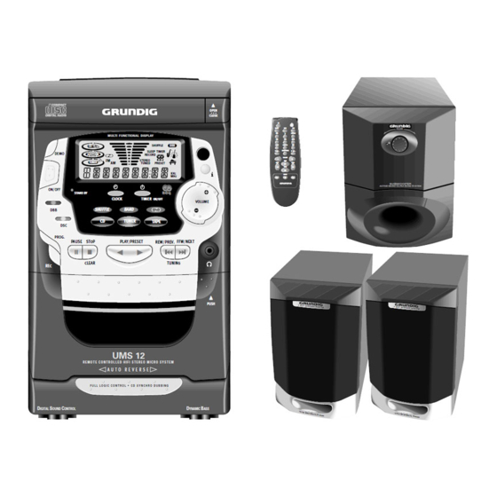
MULTI FUNCTIONAL DISPLAY
SHUFFLE
DBB
CD
Sleep TIMER
DEMO
A
B
RECORD
FM
STEREO
AM
TUNED
PRESET
KHz
MHz
ON/OFF
STAND BY
TIMER
CLOCK
ON/OFF
DBB
SHUFFLE
BAND
CD
TUNER
TAPE
DSC
PROG.
PLAY/PRESET
PAUSE
STOP
REW/PREV. FFW/NEXT
;
9
B
B
CLEAR
TUNING
REC
UMS 12
R E M O T E C O N T R O L L E D H I F I S T E R E O M I C R O S Y S T E M
A U T O R E V E R S E
F U L L L O G I C C O N T R O L
C D S Y N C H R O D U B B I N G
D
S
C
D
IGITAL
OUND
ONTROL
Zusätzlich erforderliche
Unterlagen für den Komplettservice
Additionally required
Service Manuals for the Complete Service
Service
Service
Manual
Manual
UMS 11
Sicherheit
UMS 12
Safety
UMS 12-S
Sach-Nr./Part No.
Sach-Nr./Part No.
72010-800.00
72010-757.2500
/
OPEN
CLOSE
CD
TUNER
TAPE
VCR
AUX
TV
DISPLAY
DBB
DSC
SLEEP
SHUFFLE
SIDE
BRIGHTNESS
TV VOL –
TV VOL +
VOLUME
PLAY
PREV.
NEXT
J
K
STOP
9
PAUSE
5
;
6
VOLUME
/
PUSH
2
W A Y
S P E A K E
R
S Y S T E M
B
YNAMIC
ASS
HiFi
UMS 11
UMS 12
UMS 12-S
VOLUME
SUBWOOFER
U
B
S
ACTIVE MICRO
LTRA
ASS
YSTEM
2
W A Y
S P E A K E
R
S Y S T E M
Btx * 32700 #
Sachnummer
Part Number 72010-757.2500
Änderungen vorbehalten
Subject to alteration
Printed in Germany
VK233 0298
Advertisement
Table of Contents

Related Manuals for Grundig UMS 12


Summary of Contents for Grundig UMS 12
-
Page 1: Grundig Service
Service Manual HiFi UMS 11 Grundig Service UMS 12 Hotline Deutschland..Mo.-Fr. 8.00-16.30 Uhr UMS 12-S Technik: TV/SAT 0180/52318-41 VCR/LiveCam 0180/52318-42 HiFi/Audio 0180/52318-43 Car Audio 0180/52318-44 Telekommunikation 0180/52318-45 Fax: 0180/52318-51 Ersatzteil-Bestellannahme: 0180/52318-40 Telefon: 0180/52318-50 Fax: OPEN CLOSE TUNER TAPE VOLUME... - Page 2 Exploded View UMS 12, UMS 12-S .......... 4 - 5 Explosionszeichnung Cassettenlaufwerk UMS 12, UMS 12-S . 4 - 7 Exploded View Tape Drive UMS 12, UMS 12-S ....... 4 - 7 Ersatzteilliste UMS 12 ............... 4 - 8 Spare Parts List UMS 12 ............4 - 8 Ersatzteilliste UMS 12-S ............
-
Page 3: General Section
Frequenzbereich Frequency range CrO2-Cassette (TypII) (nur UMS 12 / UMS 12-S) CrO2 tape (type II) (only UMS 12 / UMS 12-S) ............... 80 - 15.000Hz (± 2dB) ............... 80 - 15,000Hz (± 2dB) Normale Cassette (TypI) ...... 100 - 10.000Hz (± 3dB) Normal tape (type I) ...... -
Page 4: Disassembly Instructions
Allgemeiner Teil / General Section UMS 11 … UMS 12-S Ausbauhinweise Disassembly Instructions Gehäuse öffnen Removing the cover - 12 Schrauben A herausschrauben, die beiden seitlichen und die - Undo 12 screws A and remove both side covers and the top cover obere Abdeckungen abnehmen (Fig. - Page 5 UMS 11 … UMS 12-S Allgemeiner Teil / General Section 3. CD-Laufwerk und CD-PCB ausbauen 3. Removing the CD drive and the CD PCB - CD Schublade ausbauen (Pkt. 2) - Remove the CD tray (para 2) - 4 Schrauben E (Fig. 7, 8), Schraube F (Fig. 8) und 3 Schrauben G - Undo 4 screws E (Fig.
- Page 6 Allgemeiner Teil / General Section UMS 11 … UMS 12-S 5. Ausbau des CD-Antriebsriemens 5. Removing the CD Drive Belt - CD-Schublade ausbauen (Pkt. 2). - Remove the CD tray (para 2). - Mit einem kleinen Schraubendreher die Abdeckung J abheben - Unhinge the cover J with a small screw driver (Fig.
- Page 7 Fig. 21 Fig. 22 10. Cassettenschachtblende UMS 11 / UMS 12 / UMS 12-S ausbauen 10. Removing the cassette lid cover UMS 11 / UMS 12 / UMS 12-S - Cassettenklappe öffnen. - Open the cassette lid. - Rastnasen R durch Hochschieben der Cassettenschachtblende - Disengage the catches R by pushing the cover upwards and ausrasten und Blende nach vorne abnehmen (Fig.
- Page 8 16. Removing the reflex light barrier UMS 12 / UMS 12-S - Cassettenlaufwerkmotor UMS 12 / UMS 12-S ausbauen (Pkt. 14). - Remove the cassette drive motor UMS 12 / UMS 12-S (para 14). - Rastnase G ausrasten und Reflexlichtscheibe abziehen (Fig. 30).
- Page 9 UMS 11 … UMS 12-S Allgemeiner Teil / General Section 19. Front-PCB ausbauen 19. Removing the front PCB - Frontblende ausbauen (Pkt. 7). - Remove the front panel (para 7). - 4 Schrauben J herausschrauben und die beide seitlichen Halte- - Undo 4 screws J and remove the 2 holders, one on each side (Fig.
- Page 10 19 DBB (Dynamic Bass Boost) – Zum Ein- und Ausschalten der mit dem FM 75 Ω Anschluß verbunden werden. Baßverstärkung. BEDIENELEMENTE (UMS 12, UMS 12-S) FERNBEDIENUNG Einsetzen der Batterien in die ON/OFF – Zum Einschalten des Gerätes und zum Umschalten –...
- Page 11 BEDIENUNG DES SYSTEMS TUNER Sound control Speichern von Vorwahlsendern MULTI FUNCTIONAL DISPLAY Es können bis zu zwanzig Sender im FM-Band (UKW) OPEN Einstellen der Lautstärke CLOSE DEMO und 10 Sender im AM-Band gespeichert werden. • Drücken Sie die Taste VOLUME + oder – am STEREO TUNER Wenn ein Vorwahlsender angewählt wird, wird die...
- Page 12 CASSETTENDECK (UMS 12, UMS 12-S) CD-SPIELER Wiedergabe einer Cassette Dauerwiedergabe Warnung! Die Taste TAPE ( ∫ ) (oder die Taste SIDE auf 1 Drücken Sie die Taste TAPE am Gerät oder 1 Dieses Gerät ist für herkömmliche CDs OPEN CLOSE...
- Page 13 EINSTELLEN DER UHRZEIT EINSTELLEN DES TIMERS TIMER SETTING WEITERE LEISTUNGSMERKMALE Einstellen des Timers MULTI FUNCTIONAL DISPLAY Stummschaltung • Das System kann automatisch zu einer bestimm- Mit dieser Funktion kann der Ton der Anlage 3a Wenn REC TU gewählt wird, Setzen Sie eine DEMO ten Uhrzeit auf TUNER-, CD-, TAPE- oder zeitweilig abgeschaltet werden, wenn Sie einen...
- Page 14 CONTROLS (UMS 12, UMS 12-S) REMOTE CONTROL Inserting the batteries into the ON/OFF – to switch the set on or to standby mode. – to switch the unit to standby mode. Remote Control DEMO – to display the various features offered by the system.
- Page 15 Notes: For CD recording see CD Synchro-start or that it is a non RDS station. recording under Compact Disc section. During recording, it is not possible to listen to another sound source. CASSETTE DECK (UMS 12, UMS 12-S) CD PLAYER Tape Playback Continuous Playback Warning! The button TAPE ( ∫...
- Page 16 CD PLAYER CD PLAYER Selecting a desired track Changing the display mode Programming Tracks during playback Programming tracks of a loaded CD is possible in Selecting a desired track at the stop mode You can change to a different type of time the stop mode of the CD.
- Page 17 UMS 11 … UMS 12-S Abgleichvorschriften / Adjustment Procedures Abgleichvorschriften 1. Tuner Meßgeräte: Meß-/Wobbelsender, Oszilloskop, Klirrfaktormeßgerät, DC-Voltmeter, NF-Voltmeter Servicearbeiten nach Austausch des Frontends: Abgleich Nr. 3 Das Frontend ist ein komplett abgeglichener Baustein. Nur das ZF-Filter muß dem ZF-Verstärker angeglichen werden.
- Page 18 Meßgeräte/Meßmittel: NF-Voltmeter, Frequenzzähler, Testkassette 448A Sach-Nr.: 35079-023.00 Abgleich Vorbereitung Abgleichvorgang 1. Azimut Nur UMS 12, UMS 12-S: Cassettenfachblende mit einem UMS 11 UMS 12 kleinen Schraubendreher abhebeln. Die Einstellschrau- UMS 12-S ben sind nun durch Aussparungen in der Front zugänglich.
-
Page 19: Adjustment Procedures
UMS 11 … UMS 12-S Abgleichvorschriften / Adjustment Procedures Adjustment Procedures 1. Tuner Measuring instruments: Standard/sweep signal generator, Oscilloscope, Distortion meter, DC voltmeter, AF voltmeter Service works after replacing the front end: Alignment no. 3 The front end is a completely adjusted module. Only the IF filter is to be tuned to the IF amplifier. -
Page 20: Tape Deck
AF voltmeter, Frequency counter, test cassette 448A Part No.: 35079-023.00 Alignment Preparation Procedure 1. Azimuth Only UMS 12, UMS 12-S: Remove the cassette lid cover UMS 11 UMS 12 by means of a small screw driver. The adjustment screws UMS 12-S can now be set through the holes in the cassette lid. - Page 21 UMS 11 … UMS 12-S Schaltpläne und Druckplattenabbildungen / Circuit Diagrams and Layout of PCBs UMS 11 … UMS 12-S Schaltpläne und Druckplattenabbildungen / Circuit Diagrams and Layout of PCBs Schaltpläne und Druckplattenabbildungen / Circuit Diagrams and Layout of PCBs...
- Page 22 UMS 11 … UMS 12-S Schaltpläne und Druckplattenabbildungen / Circuit Diagrams and Layout of PCBs UMS 11 … UMS 12-S Verdrahtungsplan UMS 11 / Wiring Diagram UMS 11 Verdrahtungsplan UMS 12, UMS 12-S / Wiring Diagram UMS 12, UMS 12-S SHUFFLE SHUFFLE REPEAT ALL...
- Page 23 UMS 11 … UMS 12-S Schaltpläne und Druckplattenabbildungen / Circuit Diagrams and Layout of PCBs UMS 11 … UMS 12-S Schaltpläne und Druckplattenabbildungen / Circuit Diagrams and Layout of PCBs IC-Blockschaltpläne / IC Block Diagrams Latch 1 Register Stage 1...
- Page 24 Schaltpläne und Druckplattenabbildungen / Circuit Diagrams and Layout of PCBs UMS 11 … UMS 12-S Schaltpläne und Druckplattenabbildungen / Circuit Diagrams and Layout of PCBs UMS 11 … UMS 12-S Hauptplatte UMS 11 / Main Board UMS 11 KV1236Z VD500...
- Page 25 UMS 11 … UMS 12-S Schaltpläne und Druckplattenabbildungen / Circuit Diagrams and Layout of PCBs UMS 11 … UMS 12-S Schaltpläne und Druckplattenabbildungen / Circuit Diagrams and Layout of PCBs IC500 LA1832M IC502 BA4558N IC504 LC72131 VOLTS VOLTS VOLTS 10U/10V...
- Page 26 Schaltpläne und Druckplattenabbildungen / Circuit Diagrams and Layout of PCBs UMS 11 … UMS 12-S Schaltpläne und Druckplattenabbildungen / Circuit Diagrams and Layout of PCBs UMS 11 … UMS 12-S Hauptplatte UMS 11 / Main Board UMS 11 2SA1317 Für die tatsächliche Bauteilbestückung ist das Schaltbild maßgebend!
- Page 27 Schaltpläne und Druckplattenabbildungen / Circuit Diagrams and Layout of PCBs UMS 11 … UMS 12-S Schaltpläne und Druckplattenabbildungen / Circuit Diagrams and Layout of PCBs Hauptplatte UMS 12, UMS 12-S / Main Board UMS 12, UMS 12-S Für die tatsächliche Bauteilbestückung ist das Schaltbild maßgebend! Q530...
- Page 28 Schaltpläne und Druckplattenabbildungen / Circuit Diagrams and Layout of PCBs UMS 11 … UMS 12-S Schaltpläne und Druckplattenabbildungen / Circuit Diagrams and Layout of PCBs UMS 11 … UMS 12-S Hauptplatte UMS 12, UMS 12-S / Main Board UMS 12, UMS 12-S KV1236Z VD500 L500...
- Page 29 UMS 11 … UMS 12-S Schaltpläne und Druckplattenabbildungen / Circuit Diagrams and Layout of PCBs UMS 11 … UMS 12-S Schaltpläne und Druckplattenabbildungen / Circuit Diagrams and Layout of PCBs IC500 LA1832M IC502 BA4558N IC504 LC72131 VOLTS VOLTS VOLTS 10U/10V...
- Page 30 Schaltpläne und Druckplattenabbildungen / Circuit Diagrams and Layout of PCBs UMS 11 … UMS 12-S Schaltpläne und Druckplattenabbildungen / Circuit Diagrams and Layout of PCBs UMS 11 … UMS 12-S Bedienplatte / Panel Board R122 100R CDDOOR Für die tatsächliche Bauteilbestückung ist das Schaltbild maßgebend!
- Page 31 Schaltpläne und Druckplattenabbildungen / Circuit Diagrams and Layout of PCBs Kopfhörerplatte / Head Phone Board Trafoplatte / Transformer Board 180R UMS11/UMS12/UMS12S UMS 11: T1.6A L/250V HEADPHONE BOARD REVISION2(10/5/97) UMS 12 / UMS 12-S: T2A L/250V R601 C601 180R CON600 AC23V R600 AC23V...
- Page 32 Schaltpläne und Druckplattenabbildungen / Circuit Diagrams and Layout of PCBs UMS 11 … UMS 12-S Schaltpläne und Druckplattenabbildungen / Circuit Diagrams and Layout of PCBs UMS 11 … UMS 12-S CD-Platte / CD Board VREF CE416 CE415 100/6.3V 100/6.3V COIN...
- Page 33 UMS 11 … UMS 12-S Schaltpläne und Druckplattenabbildungen / Circuit Diagrams and Layout of PCBs UMS 11 … UMS 12-S Schaltpläne und Druckplattenabbildungen / Circuit Diagrams and Layout of PCBs CD-Platte / CD Board IC200 LC86P7248 Für die tatsächliche Bauteilbestückung ist das Schaltbild maßgebend!
- Page 34 Schaltpläne und Druckplattenabbildungen / Circuit Diagrams and Layout of PCBs UMS 11 … UMS 12-S Schaltpläne und Druckplattenabbildungen / Circuit Diagrams and Layout of PCBs UMS 11 … UMS 12-S Cassettenteil UMS 11 / Cassette Part UMS 11 3 - 27...
- Page 35 UMS 11 … UMS 12-S Schaltpläne und Druckplattenabbildungen / Circuit Diagrams and Layout of PCBs UMS 11 … UMS 12-S Schaltpläne und Druckplattenabbildungen / Circuit Diagrams and Layout of PCBs U200 TA8142AP U201 upc1330HA VOLTS VOLTS 1.25 2.05 1.43 10.21 2.05...
- Page 36 Schaltpläne und Druckplattenabbildungen / Circuit Diagrams and Layout of PCBs UMS 11 … UMS 12-S Schaltpläne und Druckplattenabbildungen / Circuit Diagrams and Layout of PCBs UMS 11 … UMS 12-S Cassettenteil UMS 12, UMS 12-S / Cassette Part UMS 12, UMS 12-S +12V CE214 Q213 0.1UF...
- Page 37 UMS 11 … UMS 12-S Schaltpläne und Druckplattenabbildungen / Circuit Diagrams and Layout of PCBs UMS 11 … UMS 12-S Schaltpläne und Druckplattenabbildungen / Circuit Diagrams and Layout of PCBs VR206 Q221 CE209 CE207 R231 R284 CON201 R265 R218 R288...
- Page 38 Schaltpläne und Druckplattenabbildungen / Circuit Diagrams and Layout of PCBs UMS 11 … UMS 12-S Schaltpläne und Druckplattenabbildungen / Circuit Diagrams and Layout of PCBs UMS 11 … UMS 12-S Subwoofer UMS 12-S 100uF/35V 56pF 10nF 100nF -32V 10uF/16V +12V...
- Page 41 TUER CD DOOR CD A057.000 75954-505.59 ABDECKUNG CASSETTENSCHACHT COVER CASSETTE COMPARTMENT A058.000 75954-505.38 CASSETTENSCHACHT CASSETTE COMPARTMENT A064.000 75954-505.49 LOGO GRUNDIG LOGO GRUNDIG A065.000 75954-505.48 LINSE / IR LENS / IR A068.000 75952-030.50 LAUFWERK KPL.CD DRIVE MECHANISM CPL. CD A069.000 75954-505.96...
- Page 42 POS. NR. ABB. SACHNUMMER ANZ. BEZEICHNUNG DESCRIPTION POS. NR. SACHNUMMER BEZEICHNUNG POS. NR. SACHNUMMER BEZEICHNUNG © POS. NO. FIG. PART NUMBER QTY. POS. NO. PART NUMBER DESCRIPTION POS. NO. PART NUMBER DESCRIPTION B040.000 75952-030.95 DAEMPFUNG DAMPING Q 110 75987-431.42 SMD TRANS. 2 SA 1037 K-R ZD 403 75987-249.73 DIODE RD 2,2 EB...
- Page 46 SCHALTER MSW-1722CV SWITCH MSW-1722CV © POS. NO. FIG. PART NUMBER QTY. 72010-754.95 BEDIENUNGSANLEITUNG OPERATING INSTRUCTIONS D/GB/F/I/P/E/NL/DK/S/FIN D/GB/F/I/P/E/NL/DK/S/FIN 75402-610.51 UMS 12 SCHWARZ UMS 12 BLACK 72010-757.25 SERVICE MANUAL D/GB SERVICE MANUAL D/GB A001.000 75954-505.76 FEDER CASS. SPRING CASS A002.000 75954-505.77 FEDER CD OPEN SPRING CD OPEN POS.
- Page 47 QUARZ 7,200 MHZ Q 111 75987-431.42 SMD TRANS. 2 SA 1037 K-R X 505 75954-505.72 CER DISC CDA 10,7MG 75402-710.51 UMS 12 S SCHWARZ UMS 12 S BLACK Q 112 75987-431.42 SMD TRANS. 2 SA 1037 K-R A001.000 75954-505.76 FEDER CASS.
- Page 48 POS. NR. ABB. SACHNUMMER ANZ. BEZEICHNUNG DESCRIPTION POS. NR. SACHNUMMER BEZEICHNUNG POS. NR. SACHNUMMER BEZEICHNUNG © POS. NO. FIG. PART NUMBER QTY. POS. NO. PART NUMBER DESCRIPTION POS. NO. PART NUMBER DESCRIPTION 75954-505.99 LAUFWERK CASS. CRH44-17 DRIVE MECHANISM CASS CRH44-17 Q 100 75987-431.42 SMD TRANS.