Table of Contents
Advertisement
Advertisement
Table of Contents

Related Manuals for Electrolux EXH09HL1W


Summary of Contents for Electrolux EXH09HL1W
-
Page 1: Service Manual
SERVICE MANUAL AIR CONDITIONER INVERTER SPLIT SYSTEM Publication number Electrolux Home Products Italy S.p.A. AIR CONDITIONER Corso Lino Zanussi, 30 I - 33080 Porcia – PN - 599 75 60-77 MODEL: Fax: + 39 0434 394096 EXH09HL1W EXH12HL1W Edition: 07-2012 Rev 0.0... - Page 2 2010-10 ADL 2/62 599 73 60-74...
- Page 3 Index 1. Safety Precautions: refer to Page 3. 2. ESD Requirements: refer to Pages 4 & 5. 3. Specifications: refer to Pages 6 to 7. 4. Component Overview: refer to Pages 8 & 9. 5. Dimention: refer to Pages 10 & 11. 6.
-
Page 4: Safe Electrical Working Practices
1. Safe Electrical Working Practices: Isolate Power Before Attempting to Service any Appliance. Remove Power cord, Fuse or Switch off the Circuit Breaker. Always check appliance with multimeter to ensure the power is disconnected. If you have to work on a live appliance all precautions must be taken. ... -
Page 5: Esd Requirements
2. ESD Requirements 210-10 ADL 5/62 599 75 60-77... - Page 6 210-10 ADL 6/62 599 75 60-77...
-
Page 7: Specifications
3. Specifications Parameter Unit Value Value Model EXH09HL1W EXH12HL1W Rated Voltage V~ 220-240 220-240 Power Rated Frequency Supply Phases Power Supply Mode Indoor Indoor 2500(700~4400) 3500(700~4500) Cooling Capacity (Min~Max) 2600(720~4200) 4000(720~4800) Heating Capacity (Min~Max) 485(170~1350) 823(150~1450) Cooling Power Input (Min~Max) 500(182~1300) - Page 8 Model of Outdoor Unit EXH09HL1WE EXH12HL1WE CHINA CHINA Compressor RESOURCES(SHENYANG) RESOURCES(SHENYANG) Manufacturer/Trademark SANYO COMPRESSOR CO. SANYO COMPRESSOR CO. C-6RZ110H1A C-6RZ110H1A Compressor Model Compressor Oil FV50S FV50S Outdoor Unit Compressor Type Rotary Rotary L.R.A. Compressor RLA 4.59 4.59 Compressor Power Input 1nt11l-3979 1nt11l-3979 Overload Protector...
- Page 9 ºC Ambient temp (cooling) 16~48 16~48 –20~+24 –20~+24 ºC Ambient temp (heating) Condenser Form Aluminum Fin-copper Tube Aluminum Fin-copper Tube Φ7.94 Φ7.94 Pipe Diameter Rows-fin Gap 2.5-1.5 2.5-1.5 Coil Length (LXDXW) 750/600 Fan Motor Speed 750/600 Output of Fan Motor Fan Motor RLA 0.23 0.23...
-
Page 10: Component Overview
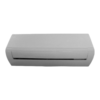
4.Component Overview (1)Power cord (2)Remote controller (3)Front panel (4)Fitter (5)Horizontal louver (6)Wall pipe (7)Binding tape (8)Connection pipe (9)Drain hose (10)Drain connecter 210-10 ADL 10/62 599 75 60-77... - Page 11 Display Panel(indoor unit) (10)Heating indicator: This indicator illuminates when the air conditioner is in HEAT mode. (11)Cooling indicator: This indicator illuminates when the air conditioner is in COOL mode (12)LED indicator (13)Power indicator: This indicator illuminates when the air conditioner is connected to the power supply. (14)Drying indicator: This indicator illuminates when the air conditioner is in DRY mode...
-
Page 12: Indoor Unit
5. Dimensions Indoor Unit Unit: mm Models W(R) EXH09HL1W 34.5 EXH12HL1W 210-10 ADL 12/62 599 75 60-77... - Page 13 EXH09HL1W (outdoor) & EXH12HL1W(outdoor) 210-10 ADL 13/62 599 75 60-77...
-
Page 14: Operating Temperatures
6. Installation Brief Operating Temperatures: Cooling & Heating models MODE Cool Heat Dehumidifier Temperature Temperature Temperature Indoor Outdoor Indoor Outdoor Indoor Outdoor 16°C~30°C 16°C~48°C 16°C~30°C -20°C~24°C 16°C~30°C 16°C~48°C 210-10 ADL 14/62 599 75 60-77... -
Page 15: Installation Site Instructions
Installation Site Instructions Proper installation site is vital for correct and efficient operation of the unit. Avoid the following sites where: ●strong heat sources, vapours, flammable gas or volatile liquids are emitted. ●high-frequency electro-magnetic waves are generated by radio equipment, ●welders and medical equipment. - Page 16 Piping Length, Elevation, Flare Work & Torque Settings Standard Additional Piping Model Length Elevation Length Refrigerant LIQUID (g/m) EXH09HL1W 9.52mm 6.00mm EXH12HL1W 9.52mm 6.00 mm Flaring work. Firmly hold copper pipe in a die in the dimension shown in The table below A(mm) OUTER DIAMETER(mm) Max.
-
Page 17: Electrical Work
Electrical Work: INPUT RATED AMP CAPACITY POWER SUPPLY CABLE SIZE Switch/Fuse EXH09HL1W 1.5 mm (power cord) 220-240V~/50Hz 16A/16A EXH12HL1W 1.5 mm (connecting cable) Connect the Cable to the Indoor Unit(instruction manual) 1.The inside and outside connecting cable can be connected without removing the front panel. -
Page 18: Electronic Function
7. Electronic Function 1.Temperature Parameters ◆ Indoor preset temperature (Tpreset) ◆ Indoor ambient temperature (Tamb.) 2.Basic Functions (The temperature in this manual is expressed by Centigrade. If Fahrenheit is used, the switchover between them is Tf=TcX1.8+32.) Once the unit is energized, the compressor shall never be restarted except 3mins interval at least. For the first energization, if the unit is at off status before power failure, the compressor can be restarted without 3-min delay. - Page 19 (3) Heating Mode (this mode isn’t available for cooling only unit) ① Heating Conditions and Process When Tamb. ≤Tpreset+2℃, the unit operates in cooling mode. Compressor and outdoor fan operate and indoor fan operates according to cold air prevention. When Tamb.≥Tpreset+5℃, compressor and outdoor fan stop operation, while indoor fan operates according to blowing residual heat.
- Page 20 (4) Fan Mode In fan mode, indoor fan operates at set fan speed, while compressor and outdoor fan all stop operation. In fan mode, the temperature setting range is 16~30℃. Display is displaying operation icon and set temperature. (5) Auto Mode In auto mode, the system will select the operation mode (cooling, hearing of fan mode) according to the change of ambient temperature automatically.
- Page 21 (7)SAVE Function ① In cooling mode, if press IONFilter+clock buttons on remote controller simultaneously, the controller will enter into SAVE mode. In SAVE mode, if press IONFilter+clock buttons on remote controller simultaneously again, SAVE function won’t be set again. ② If remote controller is set to display set temperature, dual-8 nixie tube display “SE”. ③...
- Page 22 Timer Change Although timer has been set, the unit still can be turned on/off by pressing ON/OFF button of the remote controller. You can also set the timer once again, and then the unit will operate according to the last setting. If timer ON and timer OFF are set at the same time during operation of the unit, the unit will keep operating at current status till OFF time reaches.
- Page 23 When Tpreset<Tamb.<Tpreset+3℃, indoor fan operates at medium speed; When Tpreset-2<Tamb.≤Tpreset, indoor fan operates at low fan speed; When Tamb. ≤Tpreset-2℃, indoor fan operates at quiet mode. ③ Auto fan speed is not available in drying mode Note: high speed, medium speed and low speed is to “notch 5”, “notch “3” and “notch 1” respectively. As for the switchover among high speed, medium speed and low speed, the unit should operates at every speed for 3minutes and 3s at least.
- Page 24 (9) Control of Left&Right Swing After energization, swing will be restored to the starting point firstly and then stop at the middle position. When setting left&right swing, swing blade has 7 statuses: left position ① , secondary left position ② , middle position ③ , secondary right position ④ , right position ⑤...
- Page 25 (14) Fahrenheit Display Function Niexie tube displays current set temperature. If the remote control signal is Fahrenheit, the temperature will be display by Fahrenheit. Set temperature range is 16~30℃(61-86℉). Under auto mode, nixie tube displays 25℃(77℉)in cooling and fan, and 20℃(68℉) in heating. Cooling only controller only displays 25℃(77℉). (15) Locked Protection to Indoor Fan If the indoor fan motor keeps low rotation speed for a continuous period of time after startup, the unit will stop operation and display “H6”.
-
Page 26: Schematic Diagram
8.Schematic Diagram 8.1 Electrical Wiring Indoor Unit Outdoor Unit Cooling & Heating Models 210-10 ADL 26/62 599 75 60-77... -
Page 27: Printed Circuit Board
8.2 Printed Circuit Board Indoor Unit ●TOP VIEW Interface name Interface name Interface name Indoor and outdoor Small motor for vertical Health interface communication port swing Outdoor power supply Neutral wire interface Horizontal swing interface motor for vertical DC fan motor Live wire interface swing Electrostatic dedusting... - Page 28 ●BOTTOM VIEW 210-10 ADL 28/62 599 75 60-77...
-
Page 29: Outdoor Unit
Outdoor Unit ●TOP VIEW Interface name Interface name Interface name Input of neutral wire of Live wire of electric Interface of fan power heater Neutral wire of Input of live wire of electric heater of Input of overload power chassis Neutral wire of Communication electric heater of... -
Page 30: Troubleshooting
9. Troubleshooting Safety Please insure stored voltage is discharged/removed from all relevant high voltage capacitors, by the use of a 25 to 40 watt incandescent globe. As illustrated below. Electrolytic Capacitors (HIGH VOLTAGE! CAUTION!) Bulb (25-40W) 210-10 ADL 30/62 599 75 60-77... -
Page 31: Error Codes
Diagnosis and Solution: Error Code Display of lamp (the times of blinking) Display Page Name of malfunction of indoor Indoor Outdoor unit Running Cooling Heating Yellow Green Anti-freezing protection System block or refrigerant leakage Compressor exhaust high temperature protection AC over-current protection Communication failure between indoor unit and outdoor unit Anti-high temperature protection... -
Page 32: Function Of Indoor Controller
Function of Indoor Controller: 1. Interfaces Diagram of Indoor Mainboard Silk screen Interface Silk screen on PCB Interface on PCB DC-MOTOR Interface of DC motor TUBE Interface of indoor pipe temp sensor Electrostatic Interface for communication between indo CLEAN COM-OUT and outdoor units dedusting interface Inching switch... - Page 33 2. Diagram of Display When the Unit is Standby 3. Troubleshooting of Indoor Unit 3.1 Malfunction Code Table of Indoor Unit 210-10 ADL 33/62 599 75 60-77...
- Page 34 3.2 Each Troubleshooting and Schematic Diagram 3.2.1 Firstly, check if power supply is normal Check if power supply is normal and the voltage is between 165V~235V. 3.2.2 Refer to Malfunction Code Table and confirm the malfunction according to malfunction code displayed on indoor unit.
- Page 35 F1,F2 Malfunctions: Flowchart: Start Is the wiring terminal between temperature sensor and the controller loosened or poorly contacted? Insert the temperature sensor tightly Malfunction is eliminated Is there short circuit due to tri-pover of the parts? Make the parts upright Malfunction is eliminated Is the temperature sensor...
- Page 36 H6 Malfunction (2) Malfunction of Indoor Motor There is no feedback from indoor motor: H6 is displayed and LED lamp is off for 3s and blinks for 11 times. (That the LED lamp is on for 0.5s and off for 0.5s is a blink.) Interface of DC motor;...
- Page 37 H6 Malfunction Flowchart: 210-10 ADL 37/62 599 75 60-77...
- Page 38 C5 Malfunction (3) Malfunction of Jumper Cap Malfunction of Jumper Cap: C5 is displayed; Operation LED lamp is off for 3s and blinks for 15 times. (That the LED lamp is on for 0.5s and off for 0.5s is a blink.) Function of jumper cap: determine swing angle of different models and rotational speed of indoor fan.
- Page 39 C5 Malfunction Flowchart: C5 is displayed on the unit. Install a Is there jumper cap matching on the controller? jumper cap Is the malfunction eliminated? Is the jumper cap Re-insert the inserted incorrectly jumper cap or improperly? Is the malfunction eliminated? Replace the jumper cap...
- Page 40 E6 Malfunction (4) Communication Malfunction between Indoor and Outdoor Units Communication malfunction between indoor and outdoor units: E6 is displayed and operation LED lamp is off for 3s and blinks for 6 times. (That the LED lamp is on for 0.5s and off for 0.5s is a blink.) When communication between indoor and outdoor units is normal, communication LED lamp of indoor unit blinks ( off for 0.5s and on for 0.5s).
- Page 41 4. Cautions: (1) Before replacing indoor mainboard, check if the substituted mainboard is qualified. The following tests shall be done: a. Test if protective tube FUSE1 is open-circuit. If so, replace it with a protective tube of same model. b. Energize the unit to test if the buzzer will sound. If not, this mainboard of the indoor unit can’t be used. c.
- Page 42 Detection point 10 Detection point Detection point Detection point Detection point Detection point Detection Detection point Detection point 9 Detection point 7 point 6 210-10 ADL 42/62 599 75 60-77...
-
Page 43: Each Malfunction And Diagram
3. Troubleshooting of Outdoor Unit 3.1 Firstly, check if power supply is normal Check if power switch is turned on and the voltage is between 165V~253V. 3.2 Malfunction Code Table of Outdoor Unit LED Lamp Nixie Malfunction Name Yellow LED Red LED Green LED Tube... - Page 44 # Example of LED sequence: Single fault code sequence. Mutable fault code sequence. (2) Low Voltage protection PL is displayed on indoor unit Yellow LED lamp of outdoor unit blinks for 12 times # Check voltage of power supply. (3) High voltage protection PH is displayed on indoor unit Yellow LED lamp of outdoor unit blinks for 13 times.
- Page 45 (4) Communication Malfunction E6 is displayed on indoor unit Green LED lamp of outdoor unit doesn’t blink. # If there is no LED lamp blinking, 1. Measure voltage between N1 (neutral wire ) and 3 (live wire) on patching board of outdoor electric box by AC voltage grade of universal meter.
- Page 46 (6) Over current protection E5 is displayed on indoor unit Yellow LED lamp of outdoor unit blinks for 5 times #It indicates that the current of the complete unit is too large. Check if voltage of power supply is normal. (7) EEPROM Reading and Writing Malfunction EE is displayed on indoor unit Yellow LED lamp of outdoor unit blinks for 11 times...
- Page 47 (11) PFC Over Current Protection HC is displayed on indoor unit Yellow LED lamp of outdoor unit blinks for 14 times # Check if the power supply voltage is normal # Check if there is short circuit between any two pins. If so, IGBT is damaged. Replace the IGBT and turn on the unit again. If IGBT is still burnt out, the PFC drive circuit is damaged, replace the mainboard.
- Page 48 (13) Mismatching of indoor and outdoor unit LP is displayed on indoor unit Yellow LED lamp of outdoor unit blinks for 16 times # Check if jumper cap of indoor unit is applicable. Needle stand of jumper cap (14) Low Pressure Protection (refrigerant leak) (not applicable to this model) E3 is displayed on indoor unit Red LED lamp of outdoor unit blinks for 9 time # Check if refrigerant leaks and if connecting pipe is correctly connected.
- Page 49 (17) Discharge Temperature Protection E4 is displayed on indoor unit Yellow LED lamp of outdoor unit blinks for 7 times ≥98℃, the frequency is prohibited to increase; When TB discharge ≥103℃, the compressor operates at decreased frequency; When TB discharge ≥110℃, the compressor stops operation;...
- Page 50 (19) Power Protection L9 is displayed on indoor unit Yellow LED lamp of outdoor unit blinks for 9 times When Pc≥1900w, if Pc≤1800w for continuous 3min, the unit will resume normal operation; ≥2000w, the unit will operate at decreased frequency; When Pc When Pc≥2100w, compressor stops operation.
- Page 51 After replacing outdoor controller, the malfunction still exists: In that case, check if communication wire, temp sensor, fan, compressor or 4-way valve is normal. Communication wire: Check if communication wire, live wire and neutral wire are incorrectly connected, or wiring terminal is poorly connected.
-
Page 52: Appendix 1: Resistance Table Of Ambient Temperature Sensor For Indoor And Outdoor Units(15K
Appendix Appendix 1: Resistance Table of Ambient Temperature Sensor for Indoor and Outdoor Units(15K) Resistance Resistance Resistance Temp(℃) Resistance(kΩ) Temp(℃) Temp(℃) Temp(℃) (kΩ) (kΩ) (kΩ) 138.1 18.75 3.848 1.071 128.6 17.93 3.711 1.039 121.6 17.14 3.579 1.009 16.39 3.454 0.98 108.7 15.68 3.333... -
Page 53: Appendix 2: Resistance Table Of Outdoor And Indoor Tube Temperature Sensors(20K
Appendix 2: Resistance Table of Outdoor and Indoor Tube Temperature Sensors(20K) Resistance Resistance Resistance Resistance Temp(℃) Temp(℃) Temp(℃) Temp(℃) (kΩ) (kΩ) (kΩ) (kΩ) 181.4 25.01 5.13 1.427 171.4 23.9 4.948 1.386 162.1 22.85 4.773 1.346 153.3 21.85 4.605 1.307 20.9 4.443 1.269 137.2... -
Page 54: Appendix 3: Resistance Table Of Outdoor Discharge Temperature Sensor(50K
Appendix 3: Resistance Table of Outdoor Discharge Temperature Sensor(50K) Resistance Temp Resistance Temp Resistance Temp Temp(℃) Resistance(kΩ) (kΩ) (℃) (kΩ) (℃) (kΩ) (℃) 853.5 18.34 4.754 799.8 93.42 17.65 4.609 89.07 16.99 4.469 703.8 84.95 16.36 4.334 660.8 81.05 15.75 4.204 620.8 77.35... -
Page 55: Disassembly Procedure
10. Disassembly Procedure Indoor disassembly: Procedure Steps 1. Before disassembly 2. Remove panel panel Remove the clamps on left and right side of the displayer panel, to separate the panel and front case. Remove the screws fixing display, to remove the display. - Page 56 Steps Procedure 4. Remove guide louver axial bushing guide louver Pushing out the axial bushing in middle of the guide louver, slightly bend the guide louver to remove it. 5. Remove front case assy Remove the screws fixing front case. Loosen the clamps on front case.
- Page 57 6. Remove electric box assy electric box cover 1 Loosen the clasp of electric box cover; remove the electric box cover; remove the tube temperature earthin g screw sensor; remove the 3 earthing wire screws of scre evaporator and then remove the connection screw of electric box and chassis.
- Page 58 Steps Procedure 7. Remove connection pipe clamp and evaporator assy screw connection pipe clamp evaporator Remove the screws fixing connection pipe clamp, assy to remove the clamp. Remove the two screws connecting evaporator angle support and chassis, screw remove the screws fixing evaporator assy and motor clamp, loosen the clamp, slightly regulate the evaporator connection pipe position, to remove the evaporator.
- Page 59 Outdoor disassembly: Steps Procedure 1. Remove top cover Remove the screws fixing right handle and valve cover, to remove them. screw Remove the screws fixing left & right side of top cover, to remove the top cover. top cover screw 2.
- Page 60 3. Remove left and right side plate assy right side plate assy Remove the screws connecting right side plate and evaporator, electric box assy and valve support, to remove the right side plate assy. screw Left side plate assy Remove the screws connecting left side plate and evaporator to remove the left side plate assy.
- Page 61 5. Remove motor and motor support Remove the screw nut fixing motor, to remove the motor motor; remove the screws connecting motor support and chassis, to remove the motor support. motor support screw nut 6. Remove electric box assy electric box cover Remove the screw fixing electric box cover, to remove the electric box cover.
- Page 62 Steps Procedure 7. Remove four-way valve assy four-way valve Remove the screw on electromagnetic loop, to assy remove the loop. Welding cut the spot weld of four-way valve, to remove the four-way valve assy. (Release the refrigerant clearly before welding cutting) spot weld 8.