
Related Manuals for Pipistrel Sinus

Summary of Contents for Pipistrel Sinus
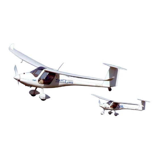
- Page 1 K i t M a n u a l f o r P i p i s t r e l S i n u s a n d V i r u s A i r c r a f t Pipistrel Sinus & Virus Kit Build Manual http://www.pipistrel.si © Pipistrel Release March 2009 © Page 1 of 267...
-
Page 2: Table Of Contents
Fitting the Wheel Spats ........................... 229 Fitting the nose wheel spat ........................233 Fitting the luggage rack and headsets....................234 Mounting the Autopilot System......................237 Automatic nose wheel and rudder centering systems ................ 245 http://www.pipistrel.si © Pipistrel Release March 2009 © Page 2 of 267... - Page 3 As this is a new version of the kit manual for Pipistrel's Sinus and Virus rcraft, we would like your feedback and suggestions on the different tasks, so we may improve the manual for future customers.
-
Page 4: What Do You Need
12.5. In order to work the wings comfortably, you're going to need a work space that is at least 9 meters long, because Sinus wings measure approximately 8 meters long. This would give you a little space at each end to move around a little more if you're making a Virus. -
Page 5: Preparing The Fuselage
K i t M a n u a l f o r P i p i s t r e l S i n u s a n d V i r u s A i r c r a f t Materials Here is a list of materials that you will definitely need when making your Pipistrel aircraft: Loctite 243... - Page 6 Sand the windscreen edge to ensure a good fit of the Lexan windscreen, paying particular attention to the section marked with ovals in the photos below. The key is to make sure the edges around the windscreen are smooth and not sharp. http://www.pipistrel.si © Pipistrel Release March 2009 © Page 6 of 267...
- Page 7 Look for the strip of raised plastic on the fuselages surface, which is a result of the fuselages manufacturing process. This will assist you in finding the center position, which in turn will be used to locate the windscreen brace. http://www.pipistrel.si © Pipistrel Release March 2009 © Page 7 of 267...
- Page 8 The factory will already have these positions marked for you in marker pen. Look at Appendix 2, 3 and 4 for hole diagrams with exact dimensions. http://www.pipistrel.si © Pipistrel Release March 2009 © Page 8 of 267...
- Page 9 K i t M a n u a l f o r P i p i s t r e l S i n u s a n d V i r u s A i r c r a f t Dremel the holes and slots, use a vacuum cleaner to keep the dust under control when cutting. http://www.pipistrel.si © Pipistrel Release March 2009 © Page 9 of 267...
-
Page 10: Preparing The Undercarriage
Slide the axle through and fix the assembly with the washer and the non-machined nyloc • nut - apply Loctite 243 to the axle's threads before assembling the washer and nyloc nut http://www.pipistrel.si © Pipistrel Release March 2009 © Page 10 of 267... - Page 11 exactly 1 cm from the brake assembly resting plate. This can be done by marking the drill. Insert the pins and tap them in with a hammer http://www.pipistrel.si © Pipistrel Release March 2009 © Page 11 of 267...
- Page 12 K i t M a n u a l f o r P i p i s t r e l S i n u s a n d V i r u s A i r c r a f t http://www.pipistrel.si © Pipistrel Release March 2009 © Page 12 of 267...
- Page 13 NUMBER 277 AND GREATER, IT IS NOT NECESSARY TO PLACE A WASHER BETWEEN THE BRAKE ASSEMBLY AND THE WHEEL. THESE MODELS HAVE AN ALTERED BRAKE ASSEMBLY WITH A BIGGER FLANGE AND THUS DO NOT REQUIRE THE WASHER. Brake assembly WITH washer http://www.pipistrel.si © Pipistrel Release March 2009 © Page 13 of 267...
- Page 14 Wheel placement: Place wheel on the axle Thoroughly grease the bearing and the wheel hub Place the bearing and apply even more grease around the bearing afterwards http://www.pipistrel.si © Pipistrel Release March 2009 © Page 14 of 267...
- Page 15 Check one last time to ensure that the wheel turns freely and quietly. Also grab the wheel with two hands and check to see that there is no free movement of the wheel along the axis. http://www.pipistrel.si © Pipistrel Release March 2009 © Page 15 of 267...
- Page 16 Drill a hole at a 45 degree angle directly beside pre-drilled hole located on top of the undercarriage's legs. Do the same for the other side. Check to make sure no sharp edges remain. http://www.pipistrel.si © Pipistrel Release March 2009 © Page 16 of 267...
- Page 17 K i t M a n u a l f o r P i p i s t r e l S i n u s a n d V i r u s A i r c r a f t http://www.pipistrel.si © Pipistrel Release March 2009 © Page 17 of 267...
-
Page 18: Fitting The Undercarriage To The Aircraft
Note: for aircraft without a nose wheel there is no recess. There are just normal bolts mounted with locknuts and a plate to hold the undercarriage in place. Setup for aircraft without a nose wheel http://www.pipistrel.si © Pipistrel Release March 2009 © Page 18 of 267... - Page 19 Wipe up any excess epoxy and grease. After 24 hours it is necessary to retighten the bolts again to 5.5 Newton meters to allow for the epoxy to come out while it is curing. http://www.pipistrel.si © Pipistrel Release March 2009 © Page 19 of 267...
- Page 20 The position is already marked in marker pen by the factory. Be careful not to go to deep or you can go through the outer shell of the aircraft, then clean up with a drill and sandpaper http://www.pipistrel.si © Pipistrel Release March 2009 © Page 20 of 267...
-
Page 21: Firewall Setup
The bottom hole for the engine mount should be approximately 42mm from the bottom surface of the fuselage. You can use this hole as a reference and then use the mount to find the other hole locations. http://www.pipistrel.si © Pipistrel Release March 2009 © Page 21 of 267... -
Page 22: Mounting The Engine To The Firewall
Mount the final bolts to hold the engine mount to the airframe. http://www.pipistrel.si © Pipistrel Release March 2009 © Page 22 of 267... -
Page 23: Sound Dampening Material
With a helper, carefully position the carpet against the front wall, starting at the bottom and working to the top, pushing and making sure there is good contact. http://www.pipistrel.si © Pipistrel Release March 2009 © Page 23 of 267... - Page 24 K i t M a n u a l f o r P i p i s t r e l S i n u s a n d V i r u s A i r c r a f t http://www.pipistrel.si © Pipistrel Release March 2009 © Page 24 of 267...
-
Page 25: Painting The Fuselages Interior (Part 1)
Now mask the inside of the fuselage for painting. Paint with a brush using nitro black paint. Pay special attention to the door lip and clean up with thinners if you have any spillage. http://www.pipistrel.si © Pipistrel Release March 2009 © Page 25 of 267... - Page 26 K i t M a n u a l f o r P i p i s t r e l S i n u s a n d V i r u s A i r c r a f t http://www.pipistrel.si © Pipistrel Release March 2009 © Page 26 of 267...
-
Page 27: General Touch Ups And Painting The Fuselage (Part 2)
Rotate the fuselage upside down and support the rudder on foam padding. Set the wing roots on a frame or saw horses with sponge foam to prevent damage http://www.pipistrel.si © Pipistrel Release March 2009 © Page 27 of 267... - Page 28 Once you have masked around the canopy and skylight lip, paint the sanded and filled area with bumper paint. Use bumper paint as it has a good sheenless colour and the finish fills in small imperfections in the body filler. http://www.pipistrel.si © Pipistrel Release March 2009 © Page 28 of 267...
-
Page 29: Lining The Fuselage Interior With Carpet And Mounting The Fuel Taps
© Pipistrel Release March 2009 © Page 29 of 267... - Page 30 Use the metal roof supports as a guide and stretch the carpet back as you go. Make sure not to cover the rear hole where the ailerons poke through. http://www.pipistrel.si © Pipistrel Release March 2009 © Page 30 of 267...
- Page 31 Fit the fuel taps using Loctite number 243 which is made for fuel and pressure fittings. Use a washer and position in the bracket as shown in the photograph. http://www.pipistrel.si © Pipistrel Release March 2009 © Page 31 of 267...
-
Page 32: Fitting The Cockpit Carpet
When dry using the soldering iron with a knife blade cut the openings in the carpet for the additional holes. http://www.pipistrel.si © Pipistrel Release March 2009 © Page 32 of 267... -
Page 33: Installation Of The Heat Duct, Oil Tank Bracket And Wire Bundle Fittings
© Pipistrel Release March 2009 © Page 33 of 267... -
Page 34: Cutting The Slots For The Fuel Gauge
Fitting the throttle assembly and the flap handle Position the throttle-choke assembly and mark holes needed for the throttle and choke cables. See Appendix 4 for a diagram of the hole locations. http://www.pipistrel.si © Pipistrel Release March 2009 © Page 34 of 267... - Page 35 Be sure to mount the flap handle so that the angle brackets point towards the engine and not towards the rudder, as shown in the diagram and pictures below. http://www.pipistrel.si © Pipistrel Release March 2009 © Page 35 of 267...
- Page 36 Remember to drill carefully, so that you don't hit the elevator pushrods. http://www.pipistrel.si © Pipistrel Release March 2009 © Page 36 of 267...
-
Page 37: Fitting The Ballistic Chute (Part 1)
Drill 4 small holes and a slot to start the cut with a jigsaw. Be sure to measure the jigsaw blade width first and use a drill with the same drill piece thickness as the jigsaw http://www.pipistrel.si © Pipistrel Release March 2009 © Page 37 of 267... - Page 38 Do the same for the surface around the hole on the inside of the fuselage. Place three strips of duct tape around the rim of both the container and the hole. Try to align them nicely. http://www.pipistrel.si © Pipistrel Release March 2009 © Page 38 of 267...
- Page 39 Also place a “handful” of rapid-dry epoxy resin to the bottom of the container. This will serve as the second fixation point between the container and the fuselage. http://www.pipistrel.si © Pipistrel Release March 2009 © Page 39 of 267...
- Page 40 Be sure to do this quick after pasting the epoxy resin on the parts because the rapid-dry will harden within 5 minutes. http://www.pipistrel.si © Pipistrel Release March 2009 © Page 40 of 267...
- Page 41 Stuff a little of the leftover normal epoxy resin around the containers base for extra holding strength. http://www.pipistrel.si © Pipistrel Release March 2009 © Page 41 of 267...
- Page 42 Spread a little epoxy resin (without cotton flock) around both fixation point rims to close all pores and make it look nice. Leave the container for 24 hours and let the epoxy resin cure. http://www.pipistrel.si © Pipistrel Release March 2009 © Page 42 of 267...
-
Page 43: Fitting The Ballistic Chute (Part 2)
Cover screws and holes with electrical tape. http://www.pipistrel.si © Pipistrel Release March 2009 © Page 43 of 267... - Page 44 it through the roof of the cockpit Be sure the seam on the bridles is down, this is important to keep the water out of the bridles. http://www.pipistrel.si © Pipistrel Release March 2009 © Page 44 of 267...
- Page 45 Apply Loctite 243 before closing the carabiner. Slide the thin rubber sleeve over the carabiner and temp it with a heat iron so that it fixes itself to the carabiner/strap junction. http://www.pipistrel.si © Pipistrel Release March 2009 © Page 45 of 267...
- Page 46 Using a reamer drill (4mm), make two 30 mm-long slots in the parachute's main holder, just above the coiled connecting strap, on on each side of the holder. http://www.pipistrel.si © Pipistrel Release March 2009 © Page 46 of 267...
- Page 47 Apply strong adhesive tape, so that they are held down well. Coil the support straps into the main holder, install the covers traps and slide the rocket assembly's pin through the loop. http://www.pipistrel.si © Pipistrel Release March 2009 © Page 47 of 267...
- Page 48 Cover with the special vinyl sticker and mark with the warning sticker ‘rocket exhaust’. Finally, apply silicone under the parachute's support straps to ensure that they are fixed to the fuselage's roof. http://www.pipistrel.si © Pipistrel Release March 2009 © Page 48 of 267...
-
Page 49: Fitting The Lower Fuel System
2 silicone tubes and a rubber hose. The second piece is rubber and silicone tube, which is used for the fuel return line. The third is a smaller junction, which connects the gasculator and fuel filler/drain. http://www.pipistrel.si © Pipistrel Release March 2009 © Page 49 of 267... - Page 50 Loctite 577 to both sets of threads on either end of the fuel filler/drain valve. The valve should open and close to the left and, if need be, slightly grind the http://www.pipistrel.si © Pipistrel Release March 2009 © Page 50 of 267...
- Page 51 The fire sleeves should be pulled forward a good 2 cm from the firewall under the cabin floor. Close the slot up around the fire sleeves using black silicone. http://www.pipistrel.si © Pipistrel Release March 2009 © Page 51 of 267...
- Page 52 Lastly, fix a fuel valve to the installed bracket just as done before. The valve handle should open downwards. Use Loctite 577, heat the tube ends and tighten with cable ties. http://www.pipistrel.si © Pipistrel Release March 2009 © Page 52 of 267...
- Page 53 K i t M a n u a l f o r P i p i s t r e l S i n u s a n d V i r u s A i r c r a f t http://www.pipistrel.si © Pipistrel Release March 2009 © Page 53 of 267...
-
Page 54: Fitting The Velcro For The Seats
There are 4 pieces under the seat base, one for the carpet near the pedals and three pieces hold on the headrests. Finally cover the Velcro with tape to keep it clean for the rest of the construction http://www.pipistrel.si © Pipistrel Release March 2009 © Page 54 of 267... -
Page 55: Rudder Pedal Preparation
If the holes are the right direction there will be no binding in the cables. All the holes have a diameter of 6mm. http://www.pipistrel.si © Pipistrel Release March 2009 © Page 55 of 267... -
Page 56: Seat Belt Preparation
The factory uses an electric drill for the tapping, but they recommend that the kit builder should do this procedure by hand. http://www.pipistrel.si © Pipistrel Release March 2009 © Page 56 of 267... - Page 57 Leave the fitting of the seat belts to much later in the process – its one of the last jobs and they will be protected from damage while fitting other items. http://www.pipistrel.si © Pipistrel Release March 2009 © Page 57 of 267...
-
Page 58: Drilling The Rudder Cable Holes
Mount the rudder cable outers using the supplied pressure hose Feed them under the seats towards the rear bulkhead as shown below http://www.pipistrel.si © Pipistrel Release March 2009 © Page 58 of 267... - Page 59 The driver's left pedal rudder outer and the passenger's right pedal rudder outer should cross here. The material is soft foam, so be careful when drilling. Use a vacuum to keep debris out of the bearings. http://www.pipistrel.si © Pipistrel Release March 2009 © Page 59 of 267...
- Page 60 1 cm exposed and in the rear cut off the tubes to about 75mm long behind the first bulkhead. http://www.pipistrel.si © Pipistrel Release March 2009 © Page 60 of 267...
-
Page 61: Mounting The Pedals
Place the pedals and bolt them in with the one lower middle screw in the front mounting plate. Use a spirit level to make sure the pedals are level. http://www.pipistrel.si © Pipistrel Release March 2009 © Page 61 of 267... - Page 62 Drill one 6mm hole and insert a bolt. Check the alignment of everything and, when satisfied, drill the remaining 3 holes and insert the washers, nyloc nuts from behind. http://www.pipistrel.si © Pipistrel Release March 2009 © Page 62 of 267...
- Page 63 Fix the cable outer to the insert using a little Loctite 406. Trim the cable outer, so that approx. 30 mm of outer remains under the cabin floor and none remains in the cabin. See picture below. http://www.pipistrel.si © Pipistrel Release March 2009 © Page 63 of 267...
- Page 64 Hold a lighter to the cable outer so that the bend will hold. Fit the cable with an insert. The picture below shows how the insert-cable outer is to be mounted. http://www.pipistrel.si © Pipistrel Release March 2009 © Page 64 of 267...
- Page 65 Now trim the cable outer inside the cabin flush to the insert. Under the cabin floor be sure to leave approximately 50mm of cable outer. http://www.pipistrel.si © Pipistrel Release March 2009 © Page 65 of 267...
- Page 66 Hold the chord taut (not slack and not too tight) and measure the distance from the rivet to the end of the chord. It should measure approx. 35 mm. http://www.pipistrel.si © Pipistrel Release March 2009 © Page 66 of 267...
- Page 67 (or to the carbon support), and the other end to the pedal adjustment cord, just between the two cable outers. Do the same with another spring between the hole in the carbon support and the other pedal adjustment cord. http://www.pipistrel.si © Pipistrel Release March 2009 © Page 67 of 267...
- Page 68 K i t M a n u a l f o r P i p i s t r e l S i n u s a n d V i r u s A i r c r a f t http://www.pipistrel.si © Pipistrel Release March 2009 © Page 68 of 267...
-
Page 69: Fitting The Rudder Cables
Then find the hole that leads into the cabin and, being careful not to puncture/damage the cabin interior wall, gently tap the end screw through. Then feed the cables through the pedal S-pipe, out the end and into the cable outers. http://www.pipistrel.si © Pipistrel Release March 2009 © Page 69 of 267... -
Page 70: Mounting The Upper Flaperon Pushrod Bracket
Recheck the measurements and, when satisfied that it has not moved, drill the remaining three holes and insert the bolts. Use Loctite 262 on the 4 nuts. http://www.pipistrel.si © Pipistrel Release March 2009 © Page 70 of 267... -
Page 71: Mounting The Electrical Panel
CDI unit, pull the electrical cables through the dash for connection to the instruments. http://www.pipistrel.si © Pipistrel Release March 2009 © Page 71 of 267... -
Page 72: Fitting The Rudder Assembly
80 mm. Fit the bolt and nut in the rear where the pushrod joins the bracket. When fitting the rear bolt you must use the special 1mm thick http://www.pipistrel.si © Pipistrel Release March 2009 © Page 72 of 267... - Page 73 Again fit the bolt with two washers as bearings and the nut with Loctite 262. Finally check the whole assembly for movement and mark the nuts with red paint. Depending on which aircraft you have, Sinus or Virus, you now have to insert the bolt to ...
- Page 74 Fit the rudder stops and the nyloc securing nuts. Then fit the rudder attachment bracket. Apply grease to the bushing for lubrication and attach it to the aircraft, using Loctite 262 on the nuts. http://www.pipistrel.si © Pipistrel Release March 2009 © Page 74 of 267...
- Page 75 K i t M a n u a l f o r P i p i s t r e l S i n u s a n d V i r u s A i r c r a f t http://www.pipistrel.si © Pipistrel Release March 2009 © Page 75 of 267...
- Page 76 5mm. Put grease on the cable ends and insert the small bush and position into the bracket. Fix the bolt and nut with Loctite 243. http://www.pipistrel.si © Pipistrel Release March 2009 © Page 76 of 267...
- Page 77 K i t M a n u a l f o r P i p i s t r e l S i n u s a n d V i r u s A i r c r a f t Must be less than 5mm or it wont fit properly – use lots of grease http://www.pipistrel.si © Pipistrel Release March 2009 © Page 77 of 267...
- Page 78 Loctite 243 on the nuts. NOTE: The Sinus has two cables from the front and one cable to the rear. The Virus has an extra cable which leads to the front and is used to steer the nose wheel. If you need to adjust the freeplay in the pedals it can be done by adjusting the screws in the firewall.
- Page 79 Fit the top rudder support post. First find the location and mark with a pen, then sand the back of the fitting and the area where it is going to mount and prepare a small http://www.pipistrel.si © Pipistrel Release March 2009 © Page 79 of 267...
- Page 80 The bracket must be left in place for 1 day to allow the epoxy to cure before it can be drilled and bolted (this will probably be fitted at the factory for safety reasons) Wipe off the extra epoxy http://www.pipistrel.si © Pipistrel Release March 2009 © Page 80 of 267...
-
Page 81: Horizontal Stabilizer Preparation
Sand the leading edge with 1500 wet and dry to get a perfect finish. If there are any little holes in the seam, fill them with white flexible polyester filler. http://www.pipistrel.si © Pipistrel Release March 2009 © Page 81 of 267... - Page 82 the rudder or wings for spraying. Make sure the surface is immaculately clean/dry and mask the leading edges with tape and plastic to protect them from getting sprayed. http://www.pipistrel.si © Pipistrel Release March 2009 © Page 82 of 267...
-
Page 83: Preparing The Elevator / Rudder
Use a Dremel again to tidy up the sides of the posts; they must be clean and unobstructed. http://www.pipistrel.si © Pipistrel Release March 2009 © Page 83 of 267... - Page 84 K i t M a n u a l f o r P i p i s t r e l S i n u s a n d V i r u s A i r c r a f t Now make shallow slots in the edge of the elevator in front of the hinges. This will provide clearance for the elevator. Use the following pictures as examples. http://www.pipistrel.si © Pipistrel Release March 2009 © Page 84 of 267...
- Page 85 Then secure them with Loctite 262 and reassemble, checking the position pin for tightness. Do not put tools on the pin side because if it becomes damaged you will not be able to fit the elevator unit to the aircraft. http://www.pipistrel.si © Pipistrel Release March 2009 © Page 85 of 267...
- Page 86 Clean the hinges with spirits, apply grease and refit to the stabilizer. Then repeat this process several times to ‘work the hinges in’ and allow for free movement of the elevator. When finished mark the pins with red paint. http://www.pipistrel.si © Pipistrel Release March 2009 © Page 86 of 267...
- Page 87 K i t M a n u a l f o r P i p i s t r e l S i n u s a n d V i r u s A i r c r a f t http://www.pipistrel.si © Pipistrel Release March 2009 © Page 87 of 267...
-
Page 88: Fitting The Horizontal Stabilizer
This is done to ensure this lip doesn't hinder the elevator's movement. The lip should measure approx. 5mm above the rudder's upper edge after grinding. http://www.pipistrel.si © Pipistrel Release March 2009 © Page 88 of 267... - Page 89 Drill and attach the top rudder post. The nuts are difficult to fit and require patience, so try not to drop anything. The actual post assembly is already epoxied in place in an earlier section. http://www.pipistrel.si © Pipistrel Release March 2009 © Page 89 of 267...
- Page 90 Now trial fit the horn. Sand the elavator's surface clean and remove any bumps to ensure the horn fits nicely. http://www.pipistrel.si © Pipistrel Release March 2009 © Page 90 of 267...
- Page 91 Then remove the rudder's top post and install the elavator's horn using the large washers and nyloc nuts. Be sure to apply Loctite 243 to the bolts' threads. http://www.pipistrel.si © Pipistrel Release March 2009 © Page 91 of 267...
- Page 92 K i t M a n u a l f o r P i p i s t r e l S i n u s a n d V i r u s A i r c r a f t Then attach the pushrod to the horn. Use lots of grease and apply Loctite 243. Also cover nuts with red paint as shown in the photos below. http://www.pipistrel.si © Pipistrel Release March 2009 © Page 92 of 267...
-
Page 93: Installation Of The Sliding Elevator Trim Knob
Cover the area with tape to keep the dirt and debris from the greased slider. http://www.pipistrel.si © Pipistrel Release March 2009 © Page 93 of 267... - Page 94 K i t M a n u a l f o r P i p i s t r e l S i n u s a n d V i r u s A i r c r a f t http://www.pipistrel.si © Pipistrel Release March 2009 © Page 94 of 267...
-
Page 95: Fitting The Trim System
The link on the trimmer should be mounted on the right hand side to avoid hitting the pushrod, this is important. Lastly, be sure that the link is mounted appropriately, so that the end with the bigger hole is facing upwards. http://www.pipistrel.si © Pipistrel Release March 2009 © Page 95 of 267... - Page 96 Then connect up the trim cables to the top of the trim lever, pull the cables as tight as you can and also check they are still mounted securely in the trim unit in the cockpit. http://www.pipistrel.si © Pipistrel Release March 2009 © Page 96 of 267...
- Page 97 Mark the bolts with red paint afterwards. Put tape back over the trim handle in the cockpit to keep out the dust. http://www.pipistrel.si © Pipistrel Release March 2009 © Page 97 of 267...
-
Page 98: The Control System
The whole assembly is secured with blue Loctite 243 and marked with red paint. Do not use red Loctite 262, as you may occasionally have to adjust the fittings during the life of the aircraft. http://www.pipistrel.si © Pipistrel Release March 2009 © Page 98 of 267... - Page 99 K i t M a n u a l f o r P i p i s t r e l S i n u s a n d V i r u s A i r c r a f t http://www.pipistrel.si © Pipistrel Release March 2009 © Page 99 of 267...
- Page 100 K i t M a n u a l f o r P i p i s t r e l S i n u s a n d V i r u s A i r c r a f t http://www.pipistrel.si © Pipistrel Release March 2009 © Page 100 of 267...
- Page 101 K i t M a n u a l f o r P i p i s t r e l S i n u s a n d V i r u s A i r c r a f t http://www.pipistrel.si © Pipistrel Release March 2009 © Page 101 of 267...
-
Page 102: Mounting The Control System
When fixing the assembly to the carbon support, place a wrench head here between the bearing and the bell crank (see next photo). http://www.pipistrel.si © Pipistrel Release March 2009 © Page 102 of 267... - Page 103 Install the flaperon control vertical pushrods as shown in the pictures below. Be sure to apply Loctite 243 to the nut's threads before tightening. Mark the nuts afterwards with red paint. http://www.pipistrel.si © Pipistrel Release March 2009 © Page 103 of 267...
- Page 104 Fix the assembly to the floor of the cabin using the 8 screws provided. If the mounting plates don't fit nicely to the bottom of the cabin floor, lightly grind the back edge of the plates as shown in the pictures below. http://www.pipistrel.si © Pipistrel Release March 2009 © Page 104 of 267...
- Page 105 3 full turns off the thread end is desired, as this will position the control sticks in a central position suitable for most pilots. Apply Loctite 243 and red paint. http://www.pipistrel.si © Pipistrel Release March 2009 © Page 105 of 267...
- Page 106 Then screw or unscrew the connector shaft's bearing housing by one turn, depending on the position of the control stick, and assemble the connector shaft once again. Continue doing this until the control sticks are properly aligned and parallel. http://www.pipistrel.si © Pipistrel Release March 2009 © Page 106 of 267...
-
Page 107: Nose Wheel Cable Preparation
On the rear bulkhead leave about 100mm out and secure the same way. Pull the cable outers tight before final positioning. It is very important to spray WD-40 into the cable outers for lubrication. http://www.pipistrel.si © Pipistrel Release March 2009 © Page 107 of 267... - Page 108 K i t M a n u a l f o r P i p i s t r e l S i n u s a n d V i r u s A i r c r a f t http://www.pipistrel.si © Pipistrel Release March 2009 © Page 108 of 267...
-
Page 109: Finishing The Rudder Cables
Fit the bolts to hold the cables and secure with red Loctite 262. Use silicone to seal the edges around the holder where it meets the floor of the aircraft. http://www.pipistrel.si © Pipistrel Release March 2009 © Page 109 of 267... -
Page 110: Fitting The Rudder
The rudder requires little preparation as it’s almost ready to fit when you receive it. There is a little difference between the sinus and virus rudders; the sinus rudder has a fortified base to compensate for the attachment of the rudder wheel rudder springs You need to grind a little material away from the base of the rudder where the bottom ... -
Page 111: Fitting The Brake Lines
Drill a 10 mm diameter hole just in front of the rudder cables in the center tunnel for the exit of one brake line. It should be offset 10 mm to the right of center (when looking towards the front of the aircraft). http://www.pipistrel.si © Pipistrel Release March 2009 © Page 111 of 267... - Page 112 For the left brake line, fit a rubber grommet and feed it through the hole you drilled in the middle of the cabin. Apply Loctite 406 to secure it and prevent it from wearing out. http://www.pipistrel.si © Pipistrel Release March 2009 © Page 112 of 267...
- Page 113 Feed the brake lines from the floor of the cabin through the legs as shown in the photos below: Apply Loctite 243 to the threads of the quick connect fitting. Secure the Brake line in the fitting and fit it to the wheel. http://www.pipistrel.si © Pipistrel Release March 2009 © Page 113 of 267...
- Page 114 Apply grease to all the threads and place the fitting vertical. Be sure not to pull the brake line too tight, allow a little freeplay. Remember the brake fittings have o rings and are made from aluminum, so please don’t overtighten. http://www.pipistrel.si © Pipistrel Release March 2009 © Page 114 of 267...
- Page 115 Be sure to leave quite a bit of slack in the brake lines, so that the pedals can move freely without being hindered. When completed add oil to the system. http://www.pipistrel.si © Pipistrel Release March 2009 © Page 115 of 267...
- Page 116 K i t M a n u a l f o r P i p i s t r e l S i n u s a n d V i r u s A i r c r a f t http://www.pipistrel.si © Pipistrel Release March 2009 © Page 116 of 267...
-
Page 117: Mounting The Fuel Lines In The Cabin
Position the clamps with the screw fittings close to the wing root to keep them clear of your hands etc in the cockpit and to eliminate any chance of catching clothing on them. http://www.pipistrel.si © Pipistrel Release March 2009 © Page 117 of 267... -
Page 118: Fitting The Windscreen
fuselage Then lay the windscreen into place and line it up with the fuselage center line. The windscreen will only fit one way and not the other. http://www.pipistrel.si © Pipistrel Release March 2009 © Page 118 of 267... - Page 119 The roof section has the double lip all the way around so the special fitting must be used there also. It will look terrible and require repair if you go through both layers. http://www.pipistrel.si © Pipistrel Release March 2009 © Page 119 of 267...
- Page 120 Now repeat all the steps above for the the sunroof. Be sure to check first that the mounting lip doesn't have any traces of body filler. Remove if necessary. http://www.pipistrel.si © Pipistrel Release March 2009 © Page 120 of 267...
- Page 121 This will stop cracks from developing in the screen. Use a de-burring tool on the top and bottom of the screen and roof panel to give a nice chamfered finish. http://www.pipistrel.si © Pipistrel Release March 2009 © Page 121 of 267...
- Page 122 Now you can mount the windscreen and sunroof using the provided rivets. Be sure to inspect all edges afterwards and make any necessary touch ups. http://www.pipistrel.si © Pipistrel Release March 2009 © Page 122 of 267...
-
Page 123: Installation Of The Strobes
Velcro patch supplied. Be sure to position it so that the the side with the fixation holes is facing starboard and electrical inputs are pointing towards the engine. http://www.pipistrel.si © Pipistrel Release March 2009 © Page 123 of 267... - Page 124 The picture below shows the black strobe box wire and the red/ black microphone wire connected to one side of the connector, with the grey power supply cable on the other side. http://www.pipistrel.si © Pipistrel Release March 2009 © Page 124 of 267...
- Page 125 Lastly, run the red/black wires from the connector to the microphone along the backside of the central cabin beam. http://www.pipistrel.si © Pipistrel Release March 2009 © Page 125 of 267...
-
Page 126: Fitting The Engine (Part 1)
Be careful not to drop any washers into the magneto. Also mark the crankcase just below the intake manifold with cylinder numbers 1 to 4. http://www.pipistrel.si © Pipistrel Release March 2009 © Page 126 of 267... - Page 127 K i t M a n u a l f o r P i p i s t r e l S i n u s a n d V i r u s A i r c r a f t http://www.pipistrel.si © Pipistrel Release March 2009 © Page 127 of 267...
- Page 128 Mark the metal spouts at the end of of the houses with the same cylinder numbers you marked the crankcase with before. Now remove the meal spouts and put plugs in the openings. Lastly, remove the main front bolt from the crankcase. http://www.pipistrel.si © Pipistrel Release March 2009 © Page 128 of 267...
- Page 129 K i t M a n u a l f o r P i p i s t r e l S i n u s a n d V i r u s A i r c r a f t Now take the Pipistrel plastic ventilation cover and stick the pieces of foam provided in ...
- Page 130 WITH METAL SPOUT 4. Therefore, the spout that was located above cylinder 4 before you removed it, should now be placed above cylinder 2. Apply blue Loctite 243. http://www.pipistrel.si © Pipistrel Release March 2009 © Page 130 of 267...
- Page 131 K i t M a n u a l f o r P i p i s t r e l S i n u s a n d V i r u s A i r c r a f t Now take the provided Pipistrel cooling system pipe and fit as shown in the photos below.
- Page 132 K i t M a n u a l f o r P i p i s t r e l S i n u s a n d V i r u s A i r c r a f t Now mount the black Pipistrel bracket which was provided with the kit. The throttle and ...
- Page 133 Now remove the two coils (black boxes) marked A and B along with their connector cables. Also remove the weird-shaped bracket which serves as a the connector holder. http://www.pipistrel.si © Pipistrel Release March 2009 © Page 133 of 267...
- Page 134 Arrange the connector cables so that they lay on side, while the black grounding cables line on the other. Use the photo below to see how to place them http://www.pipistrel.si © Pipistrel Release March 2009 © Page 134 of 267...
- Page 135 Mount the first one at the bottom end of the A-bracket as shown in the photos below. Be sure to use a polystop nut with blue Loctite 243. http://www.pipistrel.si © Pipistrel Release March 2009 © Page 135 of 267...
- Page 136 Find the longer rubber stopper, which has thread on both ends, and shorten one side to 8.5mm. Fit it to the bracket you just mounted above cylinder head 3, with the shorter thread facing down. http://www.pipistrel.si © Pipistrel Release March 2009 © Page 136 of 267...
- Page 137 7mm-diameter hole. When finished, clean up the edges with a file and fit it between the two A-shaped braces, just above the electronics. http://www.pipistrel.si © Pipistrel Release March 2009 © Page 137 of 267...
- Page 138 Pair connectors A and B with their respective connectors and slide them onto the prongs located between both A-shaped braces. Now pair connectors 1 and 2 with their respective connectors and slide them onto the other set of prongs. http://www.pipistrel.si © Pipistrel Release March 2009 © Page 138 of 267...
- Page 139 You can also reconnect the cables to the spark plugs now. Start putting together the fuel distributor. Pipistrel's distributor and 4 spouts are provided with the kit. Fit the two silver spouts with shorter threads on the sides and the one with a little longer threads in the center.
- Page 140 hole in it's head. Now secure the upper spout using cablewire. Utilized the holes in the upper bolt's head and the distributor. See photo's below. http://www.pipistrel.si © Pipistrel Release March 2009 © Page 140 of 267...
- Page 141 Now place the distributor on the motor as shown in the photos below. One hose gets fed towards the fuel pump, one through cylinder heads 2/4 and the last under cylinder head 3. http://www.pipistrel.si © Pipistrel Release March 2009 © Page 141 of 267...
- Page 142 920mm hose to the fuel pumps outer spout. Feed the other end of the 920mm hose between cylinder heads 1 and 2. Leave it there for future use. Clamp the distributor down using ties, but place a piece of foam underneath first. http://www.pipistrel.si © Pipistrel Release March 2009 © Page 142 of 267...
- Page 143 You can start mounting the oil cooler by giving the two holes at the front of the crankcase a nice chamfer. Then clean them up and fit the two Pipistrel extension bolts. Apply blue Loctite 243. Fit two rubber stoppers onto the ends of the extension bolts. Shorten the threads a little ...
- Page 144 Then fit the cable holder with the provided cable guide. Apply blue Loctite 243. Heat the end of a 60mm plastic hose and fit it to the end of the cable guide. Fit the throttle/choke cable plate. http://www.pipistrel.si © Pipistrel Release March 2009 © Page 144 of 267...
- Page 145 Cover the end of the cooling system pipe and turn the motor upside down. Remove the two large support brackets and also the water pump. http://www.pipistrel.si © Pipistrel Release March 2009 © Page 145 of 267...
- Page 146 Take the water pump back to the work bench and apply blue Loctite 243 to the threads of both elbows and fit them back in the marked positions. Remount the water pump on the engine. http://www.pipistrel.si © Pipistrel Release March 2009 © Page 146 of 267...
- Page 147 K i t M a n u a l f o r P i p i s t r e l S i n u s a n d V i r u s A i r c r a f t http://www.pipistrel.si © Pipistrel Release March 2009 © Page 147 of 267...
- Page 148 K i t M a n u a l f o r P i p i s t r e l S i n u s a n d V i r u s A i r c r a f t Refit the water pump with the rubber hoses, but this time add insulated sleeves to the upper two hoses as shown in the photo below. http://www.pipistrel.si © Pipistrel Release March 2009 © Page 148 of 267...
- Page 149 Do the same for the banjo fitting located on top of the crankcase. Fit it with insulated rubber hosing and position the hosing as shown in the photos below. http://www.pipistrel.si © Pipistrel Release March 2009 © Page 149 of 267...
- Page 150 If you did not order an oil thermostat with your engine then a uninsulated rubber hose can be connected from the oil pump to the oil cooler's upper spout as shown in the photos below http://www.pipistrel.si © Pipistrel Release March 2009 © Page 150 of 267...
- Page 151 Now set up the pickups. Ensure that there is a gap of 0.35mm. If the gap is not correct you can alter by adjusting the bolts beside them. http://www.pipistrel.si © Pipistrel Release March 2009 © Page 151 of 267...
- Page 152 Rotax. Thus the Sinus throttle cable pulls the throttle open against the return spring tension. In the standard Rotax throttle operation.
- Page 153 K i t M a n u a l f o r P i p i s t r e l S i n u s a n d V i r u s A i r c r a f t The photos below show the carburetors assembled and disassembled before being modified, as well as the modified carburetors. http://www.pipistrel.si © Pipistrel Release March 2009 © Page 153 of 267...
- Page 154 Crimp an aluminum cable swage to the end of the cable and trim any excess cable. Attach the choke cables in a similar fashion. Use heat shrink tubing and a heat gun to secure the cables in the fittings. http://www.pipistrel.si © Pipistrel Release March 2009 © Page 154 of 267...
- Page 155 NOTE: For this step, it is extremely important that the cable housings are always placed firmly in the fittings and that there is no slack in the cables. http://www.pipistrel.si © Pipistrel Release March 2009 © Page 155 of 267...
- Page 156 The gap needs to be 0.5mm. Use your feeler gauge to set this. Once this is set, tighten the stopper bolt another ¾ of a turn to achieve the proper minimum throttle setting. http://www.pipistrel.si © Pipistrel Release March 2009 © Page 156 of 267...
- Page 157 Use two 13mm hose clamps on either end of the sensor and a 12mm hose clamp for attaching it to the carburetor. Cover the gas-flow sensor with orange rubber insulation. Run the sensor's wire toward the carburetor end. http://www.pipistrel.si © Pipistrel Release March 2009 © Page 157 of 267...
- Page 158 The large red cable, which comes with the kit, is for the starter. Attach the cable to the lug on the starter using a plain nut and a lock washer. http://www.pipistrel.si © Pipistrel Release March 2009 © Page 158 of 267...
- Page 159 You can now begin mounting the exhaust system. Coat the cylinder head exhaust ports with Antiseize and mount the provided exhaust pipes as shown in the photos below. Fix the piping in position with the provided springs. http://www.pipistrel.si © Pipistrel Release March 2009 © Page 159 of 267...
- Page 160 Coax and adjust the exhaust system's components to achieve proper placement. Tighten the nuts at the exhaust ports. Tighten them as evenly as possible until everything is snug. http://www.pipistrel.si © Pipistrel Release March 2009 © Page 160 of 267...
- Page 161 The goal is to run the wires towards the back of the motor along the groove beside the crankcase and behind the cylinder heads. http://www.pipistrel.si © Pipistrel Release March 2009 © Page 161 of 267...
- Page 162 3 and 4. Use the hose clamps and toothed washers provided. Now mount the hose for the water pump as shown in the photo below. Mark the bolts with red paint when finished. http://www.pipistrel.si © Pipistrel Release March 2009 © Page 162 of 267...
- Page 163 K i t M a n u a l f o r P i p i s t r e l S i n u s a n d V i r u s A i r c r a f t http://www.pipistrel.si © Pipistrel Release March 2009 © Page 163 of 267...
- Page 164 Ensure that the rubber shock absorbers sit nicely and are not angled. Be sure to tighten all nylon lock nuts with a torque wrench to 24Nm and apply blue Lotite 243. http://www.pipistrel.si © Pipistrel Release March 2009 © Page 164 of 267...
- Page 165 K i t M a n u a l f o r P i p i s t r e l S i n u s a n d V i r u s A i r c r a f t http://www.pipistrel.si © Pipistrel Release March 2009 © Page 165 of 267...
- Page 166 Mount gascolator on the bracket that is attached to the lower left engine mount attach point. This is accomplished using two 1 cm spacers (Pipistrel part 1033003), two M6 x 30 hex bolts, two 6 mm flat washers, two 6 mm lock washers and two plain nuts. In addition to the lock washers.
-
Page 167: Fitting The Engine (Part 2)
4. This is the same bracket you mounted to hold the fuel line with the gas flow sensor. http://www.pipistrel.si © Pipistrel Release March 2009 © Page 167 of 267... - Page 168 Fit the each outer to its corresponding handle. Do the same for the other end of the cables. Mount them into the appropriate fittings on the carburetor cable control bracket. http://www.pipistrel.si © Pipistrel Release March 2009 © Page 168 of 267...
- Page 169 Install one bolt/pin fitting into the choke handle and the other into the throttle handle. Then fit the cable through the assembly and into the cable outer. Remove the handle covers to make this process easier. http://www.pipistrel.si © Pipistrel Release March 2009 © Page 169 of 267...
- Page 170 Trim the cable and solder a bolt/pin fitting to the end. Do the same for the other cable. Once finished, cover the carburetor control joints with grease. http://www.pipistrel.si © Pipistrel Release March 2009 © Page 170 of 267...
- Page 171 Mount the radiator overflow bottle to the upper left engine mount tube, using two hose clamps, cap screws and washers. These 16 mm hose clamps have been modified to include nutserts for securing them to the engine mount. http://www.pipistrel.si © Pipistrel Release March 2009 © Page 171 of 267...
- Page 172 Connect the radiator to the overflow bottle using blue plastic tubing. Use a heat gun to fit it over the spout and then fix it with plastic ties. Fill the radiator with the coolant solution and water. http://www.pipistrel.si © Pipistrel Release March 2009 © Page 172 of 267...
- Page 173 Lockwire the oil reservoir release bolt, found under the reservoir. See photo below. Use a heat gun to fix any left over heat shrink tubing to their corresponding fittings. http://www.pipistrel.si © Pipistrel Release March 2009 © Page 173 of 267...
- Page 174 K i t M a n u a l f o r P i p i s t r e l S i n u s a n d V i r u s A i r c r a f t http://www.pipistrel.si © Pipistrel Release March 2009 © Page 174 of 267...
-
Page 175: Fitting The Dashboard
When the dash is mounted, remove the front panel with the switches and the instruments. Then finish the wiring for the individual instruments using the pictures below and the diagram in Appendix 11. http://www.pipistrel.si © Pipistrel Release March 2009 © Page 175 of 267... - Page 176 K i t M a n u a l f o r P i p i s t r e l S i n u s a n d V i r u s A i r c r a f t http://www.pipistrel.si © Pipistrel Release March 2009 © Page 176 of 267...
- Page 177 K i t M a n u a l f o r P i p i s t r e l S i n u s a n d V i r u s A i r c r a f t http://www.pipistrel.si © Pipistrel Release March 2009 © Page 177 of 267...
-
Page 178: Fitting The Front Cowls
Turn and complete the other side. Separate the two sides and redrill the top cover's 3mm holes with a 6.2mm drill bit for the quick connect screws. http://www.pipistrel.si © Pipistrel Release March 2009 © Page 178 of 267... - Page 179 Don't mistake the quick connect screws for the fuselage rim with those for the side connecting seam (see photo below). The correct quick fit screw and fitting assembly for the cowl connection seam has a smaller washer. http://www.pipistrel.si © Pipistrel Release March 2009 © Page 179 of 267...
- Page 180 The position of the cowl is important, because if it is off center it will look terrible with the spinner, and if it is really out of alignment it will hit the spinner! http://www.pipistrel.si © Pipistrel Release March 2009 © Page 180 of 267...
- Page 181 When you are sure that everything is aligned nicely, tape the cowls to the fuselage using tape and mark a centerline at the top using the windscreen brace as a guide. Check Alignment http://www.pipistrel.si © Pipistrel Release March 2009 © Page 181 of 267...
- Page 182 Now find the centerline you marked before at the top of the upper cowl, which corresponds with the windscreen's brace. Measure 13.4 mm along the centerline towards the spinner and mark it for the third hole. http://www.pipistrel.si © Pipistrel Release March 2009 © Page 182 of 267...
- Page 183 From the first hole, measure downwards approx. 125 mm and mark this sport for the second hole. Do the same on the other side of the lower cowl http://www.pipistrel.si © Pipistrel Release March 2009 © Page 183 of 267...
- Page 184 This tube will clear the prongs on the quick connect screw. Tap the washer down until firm, in the end we have secured fittings in the top of the upper cowl http://www.pipistrel.si © Pipistrel Release March 2009 © Page 184 of 267...
- Page 185 Now redrill the fuselage holes for the bottom cowl using a 7mm self-centering drill piece. http://www.pipistrel.si © Pipistrel Release March 2009 © Page 185 of 267...
- Page 186 Locate the oil cooler's left edge and extend a line along it on the lower cowl. Extend the curved edge of the lower cowl to meet the line you've just drawn. Cutaway the material, dremel and file for a nice finish. http://www.pipistrel.si © Pipistrel Release March 2009 © Page 186 of 267...
-
Page 187: Fitting The Cowling Around The Exhaust And Final Cowl Touch Ups
Use sand paper rolled up to do the final clean up of the holes. Clean up the odd bit of firewall fluff by cutting with a sharp knife, run a small bead of black silicone around the http://www.pipistrel.si © Pipistrel Release March 2009 © Page 187 of 267... - Page 188 Then seal the foam's open edge with black silicon. Also fit self adhesive foam around the outside of the oil cooler and seal it with black silicon, as done with the air scoop. http://www.pipistrel.si © Pipistrel Release March 2009 © Page 188 of 267...
- Page 189 K i t M a n u a l f o r P i p i s t r e l S i n u s a n d V i r u s A i r c r a f t http://www.pipistrel.si © Pipistrel Release March 2009 © Page 189 of 267...
- Page 190 Finally grind away the final fit for the nose leg, have clearance of 10 mm on the sides and 20 mm to the front, have the same for the exhaust opening. http://www.pipistrel.si © Pipistrel Release March 2009 © Page 190 of 267...
-
Page 191: Propeller Setup
down. Make sure there is at least 1mm clearance. Put on the top half of the hub being sure to align to the marks on the hub. http://www.pipistrel.si © Pipistrel Release March 2009 © Page 191 of 267... - Page 192 K i t M a n u a l f o r P i p i s t r e l S i n u s a n d V i r u s A i r c r a f t http://www.pipistrel.si © Pipistrel Release March 2009 © Page 192 of 267...
- Page 193 Remove the propeller from the stand after adjusting the blade angles to be the same. Separate the prop hubs by tapping some bolts to break it open. http://www.pipistrel.si © Pipistrel Release March 2009 © Page 193 of 267...
- Page 194 K i t M a n u a l f o r P i p i s t r e l S i n u s a n d V i r u s A i r c r a f t http://www.pipistrel.si © Pipistrel Release March 2009 © Page 194 of 267...
- Page 195 There should be no step between the cowl and spinner profiles. If there is, this could have a negative impact on the aircraft's aerodynamic properties. http://www.pipistrel.si © Pipistrel Release March 2009 © Page 195 of 267...
-
Page 196: Fitting The Nose Wheel
Make sure to install the joining (trim) strip on the rear of the landing gear leg cover http://www.pipistrel.si © Pipistrel Release March 2009 © Page 196 of 267... -
Page 197: Wing Preparation
Lastly, the rivet comes from the plastic side and the end is in the metal Be sure to hold the metal in place with vice grips until riveted. Use a 4 mm drill and rivets which are 4mm by 13mm. http://www.pipistrel.si © Pipistrel Release March 2009 © Page 197 of 267... - Page 198 K i t M a n u a l f o r P i p i s t r e l S i n u s a n d V i r u s A i r c r a f t http://www.pipistrel.si © Pipistrel Release March 2009 © Page 198 of 267...
- Page 199 from the wings around the door latch position. Be very careful because the wing surface is very thin. Roughen the door pins to allow good adhesion of epoxy. http://www.pipistrel.si © Pipistrel Release March 2009 © Page 199 of 267...
- Page 200 Lastly, find the indent in wing between the airbrakes and the wingtip. Drill a 11mm hole for the tie-down ring. Clean up hole and fit with the stopper provided. Place tape over the stopper afterwards to prevent dust from getting inside. http://www.pipistrel.si © Pipistrel Release March 2009 © Page 200 of 267...
- Page 201 K i t M a n u a l f o r P i p i s t r e l S i n u s a n d V i r u s A i r c r a f t http://www.pipistrel.si © Pipistrel Release March 2009 © Page 201 of 267...
- Page 202 First mount the air brakes stops. Use blue Loctite. Then place a 4mm spacer between the cam and the airbrake stop. Temporarily fix it into place using a set of clamps as shown below. http://www.pipistrel.si © Pipistrel Release March 2009 © Page 202 of 267...
- Page 203 A diagram of Pipistrel's tool is in Appendix 13. Once this is accomplished, mark the push rod where it meets the end of the ball-end.
- Page 204 Appendix 14. It will help you with drilling the holes in the proper places. Place the tool over the end of the push rod and proceed with drilling the holes. http://www.pipistrel.si © Pipistrel Release March 2009 © Page 204 of 267...
- Page 205 Now you can fit the ball-end into the push rood and fix them with rivets. The rivets are 4mm by 7.5 mm long. Afterwards fix the ball-end to the pivot rod's forks. http://www.pipistrel.si © Pipistrel Release March 2009 © Page 205 of 267...
- Page 206 (they come a little longer than necessary). Mark the airbrakes, remove them and cut them appropriately. Mark the sides of the cover and using a large sanding block sand down the top of the airbrake until it fits. http://www.pipistrel.si © Pipistrel Release March 2009 © Page 206 of 267...
- Page 207 Then reach into the airbrake slot and adjust the ball-end by screwing it or unscrewing it (one rotation at a time) until the desired opening and closing force is achieved. Drilling the holes for the fuel level gauge: http://www.pipistrel.si © Pipistrel Release March 2009 © Page 207 of 267...
- Page 208 Mix up some epoxy and glue the fuel fittings in place. Hold in place with some strong tape and leave them overnight. Wipe off any extra epoxy before it goes hard. http://www.pipistrel.si © Pipistrel Release March 2009 © Page 208 of 267...
- Page 209 Then fit a plugged line over the breather outlet and create a vacuum in the tank using a pressure gauge. Allow it to sit for 4 hours and make sure there are no leaks in the fuel tank before it’s filled with fuel. http://www.pipistrel.si © Pipistrel Release March 2009 © Page 209 of 267...
- Page 210 When finished fit the cap and the breather fitting, use epoxy on the breather fitting and rotate the end to be at 90 degrees to the leading edge and with the vent holes to the rear. http://www.pipistrel.si © Pipistrel Release March 2009 © Page 210 of 267...
- Page 211 Also open up the other holes on the rest of the wing a few mm on the bottom side only to allow for more flap movement in the downward position. http://www.pipistrel.si © Pipistrel Release March 2009 © Page 211 of 267...
- Page 212 33 degrees down. If the flap doesn’t go the proper distance give the flap a good hit and mark the surface, this way you can see which position is hitting, all you need to do is grind it out http://www.pipistrel.si © Pipistrel Release March 2009 © Page 212 of 267...
- Page 213 Also check the trailing edge of the wing for interference. On our wings, we typically sand off about 2mm from the trailing edge on the lower surface near the wing root, however this is not always necessary. Use your own judgement. http://www.pipistrel.si © Pipistrel Release March 2009 © Page 213 of 267...
- Page 214 K i t M a n u a l f o r P i p i s t r e l S i n u s a n d V i r u s A i r c r a f t http://www.pipistrel.si © Pipistrel Release March 2009 © Page 214 of 267...
-
Page 215: Assembling The Airbrakes
Position them about 5 mm from the base of the spacer as shown in the photo. Drill two 3.5mm holes and secure the bracket with rivets (those which have a larger head). Mark the nuts with red paint. http://www.pipistrel.si © Pipistrel Release March 2009 © Page 215 of 267... - Page 216 K i t M a n u a l f o r P i p i s t r e l S i n u s a n d V i r u s A i r c r a f t http://www.pipistrel.si © Pipistrel Release March 2009 © Page 216 of 267...
- Page 217 16 and 17. You'll find one for the left wing and one for the right wing. The templates need to be lined up with the wing's spar and upper edge. Mark and drill 3mm holes and then tap them out to 4mm. http://www.pipistrel.si © Pipistrel Release March 2009 © Page 217 of 267...
- Page 218 The other end will require the wing being cut to have a clearance of 3 mm. http://www.pipistrel.si © Pipistrel Release March 2009 © Page 218 of 267...
- Page 219 Now assemble the flaperon to the wing using a decent amount of grease on the pins. Be sure to use a magnet to get the washer and nut onto the end securing pin. Then tighten http://www.pipistrel.si © Pipistrel Release March 2009 © Page 219 of 267...
- Page 220 Loctite 243. When getting the nut tension correct, tighten it up fully then back it off 1 full turn to allow free and unobstructed movement. http://www.pipistrel.si © Pipistrel Release March 2009 © Page 220 of 267...
- Page 221 It is applied about half / half over the other strip of tape. Repeat these steps for the other wing. http://www.pipistrel.si © Pipistrel Release March 2009 © Page 221 of 267...
- Page 222 K i t M a n u a l f o r P i p i s t r e l S i n u s a n d V i r u s A i r c r a f t http://www.pipistrel.si © Pipistrel Release March 2009 © Page 222 of 267...
-
Page 223: Mounting The Wings
(see pictures below). NOTE: it is VERY important that you DO NOT grind into the surface of the wing or into the actual wing spar. Focus on grinding the adhesive rim ONLY. http://www.pipistrel.si © Pipistrel Release March 2009 © Page 223 of 267... - Page 224 2 and 3 mm all the way around the wing. It is very unlikely that you will achieve this gap after mounting the wings for the first time. http://www.pipistrel.si © Pipistrel Release March 2009 © Page 224 of 267...
- Page 225 Then mount them into the roof's frame. Once mounted, the inserts should rest nicely against the surface of the wing spars. http://www.pipistrel.si © Pipistrel Release March 2009 © Page 225 of 267...
- Page 226 Drill a hole through the wing spar, trying to keep the drill as steady as possible. Do the same for the right wing spar, again using the roof's frame and the other mounted insert as guides. http://www.pipistrel.si © Pipistrel Release March 2009 © Page 226 of 267...
- Page 227 Apply red Loctite 262. Assemble the airbrake cockpit lever. The hole positions at the both ends of the lever are very important, so be sure to do this step carefully http://www.pipistrel.si © Pipistrel Release March 2009 © Page 227 of 267...
- Page 228 This is done by screwing and unscrewing the uniballs found at the end of the vertical flaperon push rods. Place levels on the flaperons and check to see that the flap handle accurately controls the flaperons movement (-5 , +9 and +18 http://www.pipistrel.si © Pipistrel Release March 2009 © Page 228 of 267...
-
Page 229: Fitting The Wheel Spats
until the correct angle is found. This is done by measuring the rear tip of the spat to the ground. For the Sinus this should measure about 130 mm, and for the Virus approximately 200 to 220 mm. Then, after positioning the spat centrally and rechecking the angle, tape the spat into ... - Page 230 K i t M a n u a l f o r P i p i s t r e l S i n u s a n d V i r u s A i r c r a f t landing gear leg and that the top of the cutout in the spat does not touch the landing gear leg. http://www.pipistrel.si © Pipistrel Release March 2009 © Page 230 of 267...
- Page 231 Inset 4 nutserts into the holes. Run a 5mm tap through the nutsert to clean up the thread. Open up the remaining holes in the spat to 5.5 mm and mount the spat with the provided bolts from the outside in. http://www.pipistrel.si © Pipistrel Release March 2009 © Page 231 of 267...
- Page 232 K i t M a n u a l f o r P i p i s t r e l S i n u s a n d V i r u s A i r c r a f t REMEMBER:mounting hole location is not as important as the angle at which the spat is mounted and/or considerable clearance between the spat and the undercarriage leg. http://www.pipistrel.si © Pipistrel Release March 2009 © Page 232 of 267...
-
Page 233: Fitting The Nose Wheel Spat
Use blue Loctite 243 on the nuts. Insert the nose wheel and the main wheel axle. Cover the head of the bolt and the nut with the plastic covers provided for aesthetics. http://www.pipistrel.si © Pipistrel Release March 2009 © Page 233 of 267... -
Page 234: Fitting The Luggage Rack And Headsets
Fitting the luggage rack and headrests There are two types of luggage racks that come with Pipistrel aircraft; soft and hard. The soft luggage rack is basically a pouch, that gets strung up between the seats and the first bulkhead. - Page 235 The last piece is also C-shaped. It gets placed over the flaperon pushrods which run vertically between the seats, just behind the cabin. Determine where to place Velcro strips and then fit the component. http://www.pipistrel.si © Pipistrel Release March 2009 © Page 235 of 267...
- Page 236 3mm thin and if you cut to close to the edge damage will result. The hole comes already market on the fuselage. http://www.pipistrel.si © Pipistrel Release March 2009 © Page 236 of 267...
-
Page 237: Mounting The Autopilot System
The pitch servomotor controls the aircraft's pitch movement and is located under the cabin floor between the main control sticks. Before installing it, you have to equip it with a few mounting plates. http://www.pipistrel.si © Pipistrel Release March 2009 © Page 237 of 267... - Page 238 They are to be measured from the fuselage's front rim (just behind and below the motor) and from it's center axis. Use a string, if need be, to make a visual reference for the central axis. The diagram shows the front end of the Sinus seen from UNDERNEATH the fuselage.
- Page 239 See the photos below to get an idea of how this is done. http://www.pipistrel.si © Pipistrel Release March 2009 © Page 239 of 267...
- Page 240 Feed the roll servomotor connector the orange wiring tube towards the back of the fuselage, while leaving the pitch servomotor connector under the cabin floor. Leave the main autopilot connector near the instrument panel. http://www.pipistrel.si © Pipistrel Release March 2009 © Page 240 of 267...
- Page 241 Once you're convinced that the servomotor and lateral assembly pushrod interact as they should and movement between the two is completely unhindered, fix the servomotor to http://www.pipistrel.si © Pipistrel Release March 2009 © Page 241 of 267...
- Page 242 This can be done by placing a ruler up against the movement restricting tabs, drawing a line across the two tabs and then cutting them off. http://www.pipistrel.si © Pipistrel Release March 2009 © Page 242 of 267...
- Page 243 The two thicker washers are to be placed on either side of the rod end, while the thinner washer gets placed between the servomotor's arm and the bolt head. http://www.pipistrel.si © Pipistrel Release March 2009 © Page 243 of 267...
- Page 244 When this completed apply Loctite 243 to the bolt, which holds the push rod to the bell crank arm. Mark all permanent fixations with red paint. http://www.pipistrel.si © Pipistrel Release March 2009 © Page 244 of 267...
-
Page 245: Automatic Nose Wheel And Rudder Centering Systems
K i t M a n u a l f o r P i p i s t r e l S i n u s a n d V i r u s A i r c r a f t Automatic Nose Wheel and Rudder Centering Systems Although the original Sinus and Virus aircraft were not equipped with automatic nose wheel and rudder centering systems, all newly-produced Sinus and Virus aircraft are and existing aircraft can be equipped with them upon owner request. - Page 246 When you've found the right position, mark it and the holes with a pen. • Clean the surface of the cockpit's floor. Use a knife to scrape away any silicon if need be. • http://www.pipistrel.si © Pipistrel Release March 2009 © Page 246 of 267...
- Page 247 K i t M a n u a l f o r P i p i s t r e l S i n u s a n d V i r u s A i r c r a f t http://www.pipistrel.si © Pipistrel Release March 2009 © Page 247 of 267...
- Page 248 Maker sure the foundation sits nicely on the cockpit floor. If need be, open up the holes a little with a dremel to ensure the bolts can be screwed and unscrewed easily. http://www.pipistrel.si © Pipistrel Release March 2009 © Page 248 of 267...
- Page 249 You might need an extra hand to help connect the other nose wheel cable. It involves pushing the already installed spring while pulling the new one and slipping a bolt into the balancing bracket. http://www.pipistrel.si © Pipistrel Release March 2009 © Page 249 of 267...
- Page 250 Each spring runs from the balancing bracket to the rudders lower post Mount the springs. Use blue Loctite 243 on the all of nuts and mark them with red paint. http://www.pipistrel.si © Pipistrel Release March 2009 © Page 250 of 267...
- Page 251 Be sure to stay in touch and we would love to get some photographs of the plane when you’re finished and airborne. Regards, Michael Coates Pipistrel-USA and the Pipistrel Team. http://www.pipistrel.si © Pipistrel Release March 2009 © Page 251 of 267...
- Page 252 K i t M a n u a l f o r P i p i s t r e l S i n u s a n d V i r u s A i r c r a f t http://www.pipistrel.si © Pipistrel Release March 2009 © Page 252 of 267...
- Page 253 K i t M a n u a l f o r P i p i s t r e l S i n u s a n d V i r u s A i r c r a f t http://www.pipistrel.si © Pipistrel Release March 2009 © Page 253 of 267...
- Page 254 K i t M a n u a l f o r P i p i s t r e l S i n u s a n d V i r u s A i r c r a f t http://www.pipistrel.si © Pipistrel Release March 2009 © Page 254 of 267...
- Page 255 K i t M a n u a l f o r P i p i s t r e l S i n u s a n d V i r u s A i r c r a f t http://www.pipistrel.si © Pipistrel Release March 2009 © Page 255 of 267...
- Page 256 K i t M a n u a l f o r P i p i s t r e l S i n u s a n d V i r u s A i r c r a f t http://www.pipistrel.si © Pipistrel Release March 2009 © Page 256 of 267...
- Page 257 K i t M a n u a l f o r P i p i s t r e l S i n u s a n d V i r u s A i r c r a f t http://www.pipistrel.si © Pipistrel Release March 2009 © Page 257 of 267...
- Page 258 K i t M a n u a l f o r P i p i s t r e l S i n u s a n d V i r u s A i r c r a f t http://www.pipistrel.si © Pipistrel Release March 2009 © Page 258 of 267...
- Page 259 K i t M a n u a l f o r P i p i s t r e l S i n u s a n d V i r u s A i r c r a f t http://www.pipistrel.si © Pipistrel Release March 2009 © Page 259 of 267...
- Page 260 K i t M a n u a l f o r P i p i s t r e l S i n u s a n d V i r u s A i r c r a f t http://www.pipistrel.si © Pipistrel Release March 2009 © Page 260 of 267...
- Page 261 K i t M a n u a l f o r P i p i s t r e l S i n u s a n d V i r u s A i r c r a f t http://www.pipistrel.si © Pipistrel Release March 2009 © Page 261 of 267...
- Page 262 K i t M a n u a l f o r P i p i s t r e l S i n u s a n d V i r u s A i r c r a f t http://www.pipistrel.si © Pipistrel Release March 2009 © Page 262 of 267...
- Page 263 K i t M a n u a l f o r P i p i s t r e l S i n u s a n d V i r u s A i r c r a f t http://www.pipistrel.si © Pipistrel Release March 2009 © Page 263 of 267...
- Page 264 K i t M a n u a l f o r P i p i s t r e l S i n u s a n d V i r u s A i r c r a f t http://www.pipistrel.si © Pipistrel Release March 2009 © Page 264 of 267...
- Page 265 K i t M a n u a l f o r P i p i s t r e l S i n u s a n d V i r u s A i r c r a f t http://www.pipistrel.si © Pipistrel Release March 2009 © Page 265 of 267...
- Page 266 K i t M a n u a l f o r P i p i s t r e l S i n u s a n d V i r u s A i r c r a f t http://www.pipistrel.si © Pipistrel Release March 2009 © Page 266 of 267...
- Page 267 K i t M a n u a l f o r P i p i s t r e l S i n u s a n d V i r u s A i r c r a f t http://www.pipistrel.si © Pipistrel Release March 2009 © Page 267 of 267...