Table of Contents
Advertisement
Quick Links
See also:
Owner's Manual
Advertisement
Table of Contents

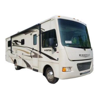
Related Manuals for Winnebago Vista


Summary of Contents for Winnebago Vista
- Page 1 Rev. 1505140826 Part No. 161500-15-018 Copyright 2014 Winnebago Industries, Inc. All rights reserved.
-
Page 3: Table Of Contents
TABLE OF CONTENTS 1 - INTRODUCTION About this Manual ..........................1-1 Safety Messages Used in this Manual ....................1-1 Pre-Delivery Inspection ........................1-2 Front Axle Tire Alignment ....................... 1-2 Service and Assistance ........................1-2 Reporting Safety Defects ........................1-2 Occupant and Cargo Carrying Capacity Label ................. 1-3 Vehicle Certification Label ....................... - Page 4 Table Of Contents Mirrors – Power Electric ........................3-6 Brake-Shift Interlock ........................3-7 Park Brake – Foot Pedal ........................3-7 Tow/Haul Transmission Mode ......................3-8 Map Light Switch ..........................3-8 Hazard Warning Flashers ........................3-8 Battery Boost Switch ........................3-8 Radio In-Dash/Rearview Monitor System ..................
- Page 5 Table Of Contents Propane Accessory Connection ......................5-2 Safe Use of the Propane Gas System ....................5-3 Propane Gas Warnings and Precautions ................... 5-4 Propane Gas Pressure Regulator ....................... 5-4 Propane Vaporization in Cold Weather .................... 5-5 6 - ELECTRICAL Electrical Cautions ..........................
- Page 6 Table Of Contents Flip-Down Screen Video Players ..................... 8-3 Audio/Video System Cables ......................8-5 TV (Dining Buffet) - Power Lift ....................... 8-5 TV – Bedroom (Flip Down) ......................8-6 Bedroom DVD/Satellite Receiver Connection ................. 8-6 TV Antenna – Digital ........................8-6 TV Signal Amplifier .........................
- Page 7 Table Of Contents Exterior Automotive Paint Finish ....................11-2 Exterior Graphic Care ........................11-4 Plastic Parts – Cleaning ........................11-4 Exterior Lights ..........................11-5 Interior Soft Goods ......................... 11-5 Ceiling Fabric Care ......................... 11-7 Cabinetry – Cleaning ........................11-8 Solid Surface Countertop – Corian® ....................11-8 Stainless Steel Appliances ......................
-
Page 9: Introduction
The instructions included in this manual are intended as a guide, and in no way DANGER indicates a hazardous situation extend the responsibilities of Winnebago which, if not avoided, will result in death or Industries beyond the standard written serious personal injury. -
Page 10: Pre-Delivery Inspection
National Highway Traffic Safety Administration delivery inspection of the chassis and all (NHTSA) in addition to notifying Winnebago motorhome components. Industries, Inc. As a part of the pre-delivery inspection... -
Page 11: Occupant And Cargo Carrying Capacity Label
SECTION 1 - INTRODUCTION or go to their website at http://www.safercar.gov or write to: Administrator, NHTSA 1200 New Jersey Avenue S.E. Washington, D.C. 20590 You can also obtain other information about motor vehicle safety from the NHTSA website at http://www.safercar.gov OCCUPANT AND CARGO CARRYING CAPACITY LABEL This label is affixed in the driver’s area next to... -
Page 12: Vehicle Certification Label
These pressure levels must be maintained to assure proper handling, safety, 2. Chassis manufacture date. and fuel economy. 3. Month and year of manufacture at Winnebago ® 9. Rear Axle Wheel Configuration: Single or Industries Dual as it relates to the inflation. -
Page 13: Specifications And Capacities
80 gal. Notes: All information is based upon the most recent data available. Visit the Winnebago Industries, Inc. web page – www.winnebagoind.com – for the most current product information. The height of each model is measured to the top of the tallest standard feature and is based on the curb weight of a typically equipped unit. -
Page 14: Owner And Vehicle Information
Motorhome Serial Number ___________________________________________________________ Chassis Vehicle Identification No. (VIN) ________________________________________________ Vehicle Mileage at Delivery __________________________________________________________ Selling Dealer Name ________________________________________________________________ Address __________________________________________________________________________ __________________________________________________________________________ ® YOUR WINNEBAGO INDUSTRIES DEALER /SERVICE CENTER Name ____________________________________________________________________________ Address __________________________________________________________________________ __________________________________________________________________________ Contact ____________________________________________Phone ________________________ CHASSIS SERVICE CENTER... -
Page 15: Safety And Precautions
SECTION 2 - SAFETY AND PRECAUTIONS GENERAL WARNINGS DRIVING SAFETY • Only seats equipped with seat belts are to be occupied while the vehicle is moving. WA RNING • Make sure all passengers have seat belts fastened. Lap belts should fit low on the hips and upper thighs. -
Page 16: Fuel And Propane Gas
SECTION 2 - SAFETY AND PRECAUTIONS • Do not operate the cruise control on icy or extremely wet roads, winding roads, in heavy WA RNING traffic, or in any other traffic situation where a constant speed cannot be maintained. • Use care when accelerating or decelerating on Propane gas containers, gasoline, or a slippery surface. -
Page 17: Propane Gas Leaks
SECTION 2 - SAFETY AND PRECAUTIONS • Open doors and other ventilating openings. • Leave the area until odor clears. DA NG E R • Have the propane system checked and leakage source corrected before using again. Do not use gas cooking appliances for Failure to comply could result in death or comfort heating. -
Page 18: Carbon Monoxide Warning
® fuel. It will detect CO gas from any combustion Winnebago Industries dealer. source such as the furnace, gas range/oven, water Further Information heater, refrigerator, chassis engine, and electric See the manufacturer’s user guide provided in... -
Page 19: Smoke Alarm
RV application. We that is also listed for RV application. We recommend obtaining a replacement from your recommend obtaining a replacement from your ® ® Winnebago Industries dealer. Winnebago Industries dealer. Further Information Further Information Please read the information provided by the See the manufacturer’s information in your... -
Page 20: Electrical
Extinguisher, the replacement must be the same type and size as the one originally supplied in MAINTENANCE your coach. We recommend obtaining a replacement only from your Winnebago • Do not remove the radiator cap while engine ® Industries dealer or a reliable RV parts supplier. -
Page 21: Slideout Rooms
SECTION 2 - SAFETY AND PRECAUTIONS Escape Window (Lift both red safety latch handles UP and push window OUT) -Typical View Slider Window Latch (Lift latch UP and slide window open) -Typical View Most slider windows along the side of any motorhome can also be used as alternate emergency exits, should the need arise. -
Page 22: Roof And Ladders
SECTION 2 - SAFETY AND PRECAUTIONS WA RNING WA RNING Do not exceed 225-lb. maximum weight Keep all persons clear of the slideout capacity. Misuse of ladder could result in room and moving parts while extending or death or serious injury. See Operator’s retracting. -
Page 23: Mold, Moisture, And Your Motorhome
® of the nature of the use of a motorhome, it is Winnebago Industries natural for a motorhome to be introduced into an If Winnebago Industries determines that mold environment with mold spores. ® ® is present in the Winnebago... -
Page 24: Jump Starting
® Winnebago Industries does not assume manual. responsibility for damage incurred while towing Never get beneath a vehicle that is held up by this vehicle. -
Page 25: Engine Overheat
SECTION 2 - SAFETY AND PRECAUTIONS NOTICE Do not attempt to push start this vehicle. Damage to the transmission or other parts of the vehicle will occur. ENGINE OVERHEAT If you see or hear steam escaping from the engine compartment or have any other reason to suspect an extreme engine overheating condition, pull the vehicle over to the roadside as soon as it is safe to do so, stop the engine, and get all... -
Page 27: Driving Your Motorhome
SECTION 3 - DRIVING YOUR MOTORHOME The information in this section refers only to features installed or adapted to the dash and Lift to Recline Power Seat driver compartment area by Winnebago Controls ® Industries . It also includes passenger seating in the living area of the coach. -
Page 28: Co-Pilot Footrest
SECTION 3 - DRIVING YOUR MOTORHOME Armrest Adjustment –If Equipped The armrests may be swung upward out of the way for easy exit or access to the front seats. A roller on the underside of the front of the armrest also lets you adjust the resting angle for personal comfort, whether the seat is upright or reclined. -
Page 29: Seat Belts
SECTION 3 - DRIVING YOUR MOTORHOME Adjustment To lengthen belt, swivel the tab end at a right angle to belt and pull strap to desired length. To shorten, pull loose end of belt. To Fasten Be sure belt is not twisted. Grasp each part of the belt assembly and push tongue into buckle. -
Page 30: Child Restraints
SECTION 3 - DRIVING YOUR MOTORHOME 2. Make sure that it will attach to your vehicle and restrain your child securely and WARNING conveniently so that you are able to install it correctly each time it is used. 3. Be certain that it is appropriate for the child's Never wear the shoulder belt in any height, weight, and development. -
Page 31: Keys
SECTION 3 - DRIVING YOUR MOTORHOME KEYS Your motorhome is supplied with several keys. In addition to the chassis manufacturer’s ignition key, you receive keys for the entrance door and exterior compartment doors. Keys have an identification number, either a small metal tag or stamped into the key head. -
Page 32: Rearview Monitor System
SECTION 3 - DRIVING YOUR MOTORHOME • Reverse step to store passenger workstation. MIRRORS – POWER ELECTRIC REARVIEW MONITOR SYSTEM –If Equipped Always adjust mirrors for maximum rear –If Equipped visibility before driving off. Make sure the seat is Your coach may be equipped with a Rearview adjusted for proper vehicle control and that you Monitor System, which lets you see what is are sitting back squarely into the seat. -
Page 33: Brake-Shift Interlock
SECTION 3 - DRIVING YOUR MOTORHOME camera view on the monitor until the turn is completed or the signal lever is canceled manually. Mirror Heat Switch (Located on driver side trim panel) -Typical View Mirror Arm/Head Adjustment If you cannot adjust a mirror properly using the control switch, the mirror may need a coarse adjustment by rotating the mirror head. -
Page 34: Tow/Haul Transmission Mode
SECTION 3 - DRIVING YOUR MOTORHOME TOW/HAUL TRANSMISSION MODE ® Ford Chassis only This mode locks out Overdrive and helps reduce gear “hunting” by the automatic transmission while towing. It also improves power delivery and uses engine braking to help control vehicle speed when descending hills. -
Page 35: Radio In-Dash/Rearview Monitor System
SECTION 3 - DRIVING YOUR MOTORHOME NOTE: The House/Coach Battery Disconnect switch near the entrance door must be ON and house batteries must be sufficiently charged for this feature to work. Basic Operating Instructions • (1) RESET - Press to reset the microprocessor. -
Page 36: Radio Power Switch
SECTION 3 - DRIVING YOUR MOTORHOME USB Cable by house batteries. If the House/Coach Battery Disconnect switch is OFF, the –If Equipped speakers will not emit sound. Your coach may be equipped with a cable to connect your USB to play through your radio. The USB cable is located on the dash beverage tray. -
Page 37: Defrost Fans
SECTION 3 - DRIVING YOUR MOTORHOME A small amount of air will blow out of all of the defrost and dash vents regardless of the mode setting. Further Information See the manufacturer’s user guide provided in your InfoCase for complete operating instructions. -
Page 38: Front Service Access
SECTION 3 - DRIVING YOUR MOTORHOME FRONT SERVICE ACCESS ENGINE ACCESS – INTERIOR (HOOD) Front Engine Cover The hood panel can be opened for access to (Located between cab seats) service items such as: NOTE: Take precautions to protect carpet and •... -
Page 39: Engine Cooling System
SECTION 3 - DRIVING YOUR MOTORHOME • Reinstall the screws at the lower front corners on each side of the engine cover (if equipped). ENGINE COOLING SYSTEM Do not remove the radiator cap while engine and radiator are still hot. Always check coolant level visually at the see-through coolant reservoir. -
Page 40: Tires
SECTION 3 - DRIVING YOUR MOTORHOME Alignment can be affected by worn steering/ suspension parts or by incidents which happen during driving, such as hitting a curb, pothole, or railroad track, etc. Improper alignment can cause tires to roll at an angle and wear unevenly. It may also cause the vehicle to “pull”... - Page 41 SECTION 3 - DRIVING YOUR MOTORHOME The circuit breakers will pop outward if they are tripped. Simply push in to reset. Always replace plug-in blade fuses with ones of the same size and amperage rating/color. Automotive 12-Volt Circuit Breakers and Fuses (Located beneath left end of dash) -Typical View Further Information...
-
Page 43: Appliances And Systems
SECTION 4 - APPLIANCES AND SYSTEMS The appliances installed in your motorhome are manufactured by reputable RV appliance makers and have been tested by independent laboratories to meet all applicable standards and codes set for RV appliances. See Section 2 - Safety and Precautions of this manual for any safety and precautions you need to take regarding the operation of your appliances. - Page 44 SECTION 4 - APPLIANCES AND SYSTEMS To be able to use both types of energy, the refrigerator does not have a compressor like household refrigerators. Instead, it uses an ammonia-water solution for cooling. Basically, ammonia vapor is distilled from the solution by heat produced from either propane gas flame or electrical heat element.
-
Page 45: Refrigerator - Residential
SECTION 4 - APPLIANCES AND SYSTEMS • Press the TEMP SET button to change temperature setting from 1 to 9 on display. NOTICE Start at the ‘coldest’ setting to ensure coldest temperature in the freezer compartment, then adjust warmer as necessary after cold food has To prevent permanent damage to the been added. -
Page 46: Ice Maker
SECTION 4 - APPLIANCES AND SYSTEMS Travel Latch NOTE: Do not force the wire shut-off arm up or down. To remove the Travel Latch, turn counter- clockwise. To reinstall the travel latch, insert into • To manually turn the ice maker off, lift the hole and turn clockwise. -
Page 47: Refrigerator Service Access Compartment - Residential Refrigerator
SECTION 4 - APPLIANCES AND SYSTEMS • CLOSED • OPEN Residential Refrigerator Service Compartment (Located along driver or passenger Refrigerator Access Door Latches sidewall, depending on model) -Typical View 2. Remove the door from the opening. To Close RANGE AND OVEN 1. -
Page 48: Microwave Oven
SECTION 4 - APPLIANCES AND SYSTEMS Unlike homes, the amount of oxygen supply is limited due to the size of the recreational vehicle, and proper ventilation when using the cooking appliances avoids dangers of asphyxiation. It is especially important that cooking appliances not be used for comfort heating, as the danger of asphyxiation is greater when the appliance is used for long periods of time. -
Page 49: Microwave Oven/Range Hood
SECTION 4 - APPLIANCES AND SYSTEMS Further Information See the manufacturer’s user guide provided inside the appliance for complete operating instructions and replacement of vent hood light bulbs and replacement or cleaning of grease filter elements. RANGE HOOD –If Equipped The range hood vent draws cooking odors and airborne grease particles into the filtration grid Microwave Oven - Typical... -
Page 50: Washer/Dryer - Prep Package
We recommend obtaining parts and service for the Washer/Dryer installation from your ® ® Winnebago or Itasca dealer. SYSTEMS MONITOR PANEL The Systems Monitor Panel provides a convenient central location for checking the -Typical View condition of all utility systems in your coach. -
Page 51: Tank Capacities
SECTION 4 - APPLIANCES AND SYSTEMS Model 35B (Equipped with Black and Gray Waste Level Selector Switches) Press either the Black or Gray Waste Level Selector switch to select the desired tank level to be displayed on the monitor panel. The approximate fluid levels are measured by electronic sensors on the sides of the tanks. -
Page 52: Power Control System (Pcs)
SECTION 4 - APPLIANCES AND SYSTEMS Battery Charge Meter POWER CONTROL SYSTEM Press and Hold the “Levels Test” switch to (PCS) check the level of charge (voltage) in the 12-volt house battery. –If Equipped The colored segments (red, yellow, and green) The Power Control System (PCS) monitors will light from the bottom up to the amount of the electrical usage of the appliances and... -
Page 53: Motoraid Water Heater
SECTION 4 - APPLIANCES AND SYSTEMS Be sure the water heater is filled with water before starting either electric or propane gas operation. To fill the water heater, turn the Water Pump switch on and open a hot water faucet anywhere in the coach. When water begins to flow steadily from the faucet, the water heater is full. -
Page 54: Pressure-Temperature Relief Valve
SECTION 4 - APPLIANCES AND SYSTEMS CAUTION NOTICE Any leak in the heat exchanger or its Hot water can escape from tank causing supply or return lines could cause loss of injury. Operate this valve only when the coolant and subsequent engine failure. tank water is cold. -
Page 55: Furnace - Propane Gas
SECTION 4 - APPLIANCES AND SYSTEMS To Shut Down FURNACE – PROPANE GAS 1. Slide Thermostat switch to the Off position. To Start Up 2. Close propane tank valve if coach will be stored for a period of time. 1. Open the Propane Gas Tank valve by turning fully “counter-clockwise”. -
Page 56: Ducted Roof Air Conditioning System
SECTION 4 - APPLIANCES AND SYSTEMS is set to automatically start the propane furnace to All cooling functions controlling to setpoint assist the Heat Pump if room temperature cools to have a short cycle protection time delay of three five degrees or more below the thermostat set minutes. -
Page 57: Propane Gas
SECTION 5 - PROPANE GAS PROPANE GAS SUPPLY Tank Gauge & Tank Fill Overflow Sender The propane gas system supplies fuel for the Valve Valve gas range/oven, water heater, furnace, and refrigerator (while in gas mode). When used and handled properly, this system is safe and economical and provides modern living conveniences wherever you travel. -
Page 58: Propane Accessory Connection
SECTION 5 - PROPANE GAS propane gas outlets in the United States do not offer any other type of liquefied petroleum gas WARNING than propane to the general public.) Check local phone directory yellow pages for locations of local propane gas refilling stations or bulk Do not fill propane container(s) to more dealerships. -
Page 59: Safe Use Of The Propane Gas System
SECTION 5 - PROPANE GAS “clockwise” to turn gas supply OFF. Rotate the SAFE USE OF THE PROPANE shut-off valve “counter-clockwise” to turn gas GAS SYSTEM supply ON. See Section 2 - Safety and Precautions in this The propane system is designed and built with manual for other safety and precautions you need strict adherence to national, state, and to be aware of related to propane. -
Page 60: Propane Gas Warnings And Precautions
SECTION 5 - PROPANE GAS • Never attach a lock or any device requiring a • Never smoke while refilling vehicle fuel tank key to the propane tank compartment door. or propane gas tank. According to standards set for recreation •... -
Page 61: Propane Vaporization In Cold Weather
SECTION 5 - PROPANE GAS Propane regulators must always be installed with the regulator vents facing downward. Regulators that are not in compartments have been equipped with a protective cover. Make sure that the regulator vent faces downward and that the cover is kept in place to minimize vent blockage that could result in excessive propane pressure causing fire or explosion. - Page 62 SECTION 5 - PROPANE GAS This means that in extremely cold weather when a large volume of gas is being used by the furnace for heating, it is possible to experience a loss of gas pressure. At first, this problem may appear to be caused by an empty tank or a regulator freeze-up, but is actually caused by failure of the liquid gas to vaporize as fast as it is needed by the furnace.
-
Page 63: Electrical
SECTION 6 - ELECTRICAL Your coach is equipped with an electrical the power converter automatically changes a system consisting of two separate voltages: portion of the 120-volt current to 12-volt DC current. All equipment in the motorhome that is • 12-volt DC system (battery current);... -
Page 64: Connecting The Power Cord
SECTION 6 - ELECTRICAL be used is designed to mate with the prongs of the power cord plug, the electrical connection can be expected to carry rated load. Connecting the Power Cord To connect to an external source, remove the cord from the utility compartment and plug it into a suitable power outlet to provide external power to the coach and converter/charger system. -
Page 65: Inverter Unit - 1000W
SECTION 6 - ELECTRICAL power fails, contact the park attendants and have them check the fuse or breaker for your supply receptacle. INVERTER UNIT – 1000W –If Equipped The inverter changes 12-volt DC battery power into 120-volt AC power for use by 120- volt AC equipment inside the coach. -
Page 66: Charging Section
SECTION 6 - ELECTRICAL Inverter Control Panel The inverter can also be used while driving the motorhome because the –If Equipped engine alternator will charge the The inverter has a wall-mounted monitor/ batteries while driving. control panel. It will also display warnings for overload conditions or other operating failure The inverter/charger unit is located in the conditions. -
Page 67: Power Center
SECTION 6 - ELECTRICAL The inverter/charger features a Battery mode, it will continue to draw from ™ Saver Mode, which is designed to keep house batteries through the inverter batteries fully charged over long periods of time. when the shoreline is unplugged unless See the inverter/charger information included in the inverter is turned OFF. -
Page 68: Circuit Breakers - House 120-Volt Ac
SECTION 6 - ELECTRICAL Charging Section The converter charges house batteries while 120-volt external power is connected. The converter will automatically “sense” the condition of the battery. If it is below “full charge”, the Charging Section will start charging the batteries. If the house batteries have been extremely discharged, they will accept charge at a relatively high amperage rate. -
Page 69: Electrical Outlets - House 120-Volt Ac
SECTION 6 - ELECTRICAL component itself. When an overload or short Bath, galley, and exterior outlets are develops, the breaker will open preventing connected to a GFCI (Ground Fault Circuit damage to the system. Interrupter), which is an extremely sensitive circuit breaker that will help to protect against Shut off the equipment (example: roof air severe electrical shock if a ground fault develops. -
Page 70: Automatic Power Transfer Switch
SECTION 6 - ELECTRICAL –If Equipped Automatic Power Transfer Switch (available with 50-amp service only) –If Equipped WARNING Whenever the generator is needed, an automatic power transfer system automatically switches the household electrical system to the Careless handling of the generator and generator 30 seconds after the generator is electrical components can be fatal. - Page 71 SECTION 6 - ELECTRICAL Automatic Generator Start (AGS) –If Equipped The Automatic Generator Start feature monitors house battery voltage and coach interior temperature, and has the ability to automatically start the Generator to help maintain full air conditioning function and house battery charge. The AGS control pad is also equipped with an hourmeter feature, which registers the total number of hours that the generator has been...
-
Page 72: Electrical System - House 12-Volt Dc
SECTION 6 - ELECTRICAL Operation Warnings and Cautions Chassis Battery The chassis battery is used to operate the engine starter and automotive accessories and WARNING controls found on the instrument panel. The slideout room systems and the electric step are also connected to the chassis battery. -
Page 73: Battery Access
SECTION 6 - ELECTRICAL NOTE: Some electronic displays and memory functions may need to be reset after power has been reconnected. See also “Battery Care” elsewhere in this section. House Chassis Batteries Battery -Typical View House/Coach Battery Disconnect Switch CAUTION (Located near entrance door) -Typical View Battery compartment must be closed and... - Page 74 SECTION 6 - ELECTRICAL The two best defenses against sulfating Further precautions are: and insufficient charge are to: • Check the state of charge periodically to avoid discharge or sulfating. 1. Turn off the House/Coach Battery Disconnect switch to avoid parasitic discharge (the trickle To ensure that the battery will always accept discharge caused by directly connected and hold a charge, follow these simple...
-
Page 75: Circuit Breakers And Fuses - House 12-Volt Dc
House 12-Volt Circuit Breakers If your coach is going to be unoccupied for (Models 35B and 35F) ® two weeks or more, Winnebago Industries -Typical View recommends disconnecting the chassis batteries in your coach to avoid battery discharge. House 12-Volt Fuses... -
Page 76: Battery Charge Meter
SECTION 6 - ELECTRICAL Automotive Chassis and House House 12-Volt Fuses 12-Volt Circuit Breakers (Located on the right-hand side (Located inside passenger compartment) of the Power Converter) -Typical View (Models 27N and 30T) -Typical View The fuse panel accepts only blade type plug-in fuses. -
Page 77: Plumbing
SECTION 7 - PLUMBING FRESH WATER SYSTEM The Fresh Water System provides water to the galley sink, shower, bathroom lavatory, toilet, and water heater. Water may be supplied by either of two sources: • A fresh water tank and water pump located within the motorhome, or •... - Page 78 SECTION 7 - PLUMBING Fresh Water Valve Fresh Water Valve (Located in water service center) (Located in water service center) -Typical View -Typical View 4. Turn city water supply ON. Using City Water 5. Use the level display on the monitor panel to When connected to an outside source of water, oversee filling of the tank, or when the tank is the water bypasses the water pump and storage...
-
Page 79: Water Pump
SECTION 7 - PLUMBING Using Tank Water (Gravity Fill) NOTE: Ensure the Fresh Water valve is in NORMAL position to use the water • Turn Water Pump switch ON. While the pump. If the valve is in Tank Fill position, switch is on, the water pump will the pump will run continuously without automatically supply tank water as needed. -
Page 80: Water Pump Switch
SECTION 7 - PLUMBING Initial Waterline Priming 1. Ensure that all water drain valves are closed, including water heater valve. 2. Turn Water Pump switch to “OFF” position. 3. Fill water tank. 4. Open all faucets, hot and cold. 5. Turn ON the Water Pump switch. 6. -
Page 81: Ice Maker Water Filter
SECTION 7 - PLUMBING NOTE: When removing the coach from storage, ICE MAKER WATER FILTER always disinfect and flush the water system thoroughly before installing a –If Equipped new filter. If the refrigerator in your coach is equipped with an ice maker, an ice maker filter is provided, DISINFECTING YOUR FRESH which removes chlorine and odors for clean, WATER SYSTEM... - Page 82 SECTION 7 - PLUMBING 4. Let the system stand at least 4 hours when disinfecting with 50 ppm residual chlorine. (If a shorter time period is desired, then a 100 WARNING ppm chlorine concentration should be allowed to stand in the system for at least 1 Chlorine is poisonous.
-
Page 83: Shower Hose Vacuum Breaker
SECTION 7 - PLUMBING detected in the water discharged. Do not and allows water remaining in the hose to drain forget the hot water faucets. down. This is a normal function of the shower (You may need to leave a hot water faucet valve assembly and is not a leak or defect. -
Page 84: Drainage System (P-Traps)
SECTION 7 - PLUMBING site. This means you can use the toilet(s), sinks, and shower even in areas where utility hookups are not available. The black water holding tank(s) contains the sewage from the toilet(s) and may include bathroom lavatory on some models. The gray water holding tank contains the waste water from the galley sink and shower, and may include Important “Don’ts”... - Page 85 SECTION 7 - PLUMBING NOTE: Model 35B is equipped with two sets of 7. Rinse sewage drain hose thoroughly with Black and Gray Waste Tank Drain water before stowing. Valves - one set is in the driver side NOTE: We recommend that you dump all compartment ahead of rear axle, and holding tanks before traveling to avoid the other set is in the driver side...
-
Page 86: Waste Water System (Waste Pump)
SECTION 7 - PLUMBING Using On-Site Sewer Hook-Ups The two black water holding tanks contain the sewage from the toilets. The gray water holding The sewage drain hose may remain attached to tank typically contains the waste water from the the sewage drain outlet and be routed out the galley sink, shower, and bathroom lavatories. - Page 87 SECTION 7 - PLUMBING Sewage Drain Hose -Typical View 2. Remove dust cap from sewage drain outlet and connect sewage drain hose. Be sure it is firmly attached. Black Waste Tank Drain Valve #1 (Front) (Located in passenger side compartment ahead of rear axle) -Typical View 5.
- Page 88 SECTION 7 - PLUMBING 8. Open the Gray Waste Tank Drain Valve (located in the water service center). Be sure there are no sags in the hose to ensure complete drainage. Close Gray Waste Tank Drain Valve as soon as tank is empty. Waste Pump Switch (Located in water service center) -Typical View...
-
Page 89: Waterline & Tank Drain Valves
SECTION 7 - PLUMBING opened. If the valves are left open, the liquids will drain off, leaving solids in the tank. Should D R A I N D R A I N this accidentally happen, disconnect the sewage C L O S E drain hose, fill the tank about half full with water, C L O S E and drive a few miles to dislodge the solids. -
Page 90: Winterizing Procedure
SECTION 7 - PLUMBING press the backflow valve “button” in the center of the inlet to drain any water trapped in the inlet line. Normal By-Pass Flow Mode CAUTION Leave bypass valve handle in NORMAL Using exterior shower to drain waterline FLOW position if draining water and -Typical View blowing out waterlines. - Page 91 A blow-out plug can be purchased accessible from the outside of the coach. ® ® (Requires socket and ratchet). at any Winnebago or Itasca dealer. City Water Connection Blow-out...
- Page 92 SECTION 7 - PLUMBING Method 2 – Antifreeze Fill 12. Turn air pressure off. Disconnect water purge adapters. Recap the city water inlet to Procedure avoid contamination by dirt or insects. (Fill plumbing lines with RV water system antifreeze) After Disconnecting Air Pressure 13.
- Page 93 SECTION 7 - PLUMBING Antifreeze Siphon Tube • Insert into container of RV water system antifreeze Winterization Valve • Point toward antifreeze siphon tube to Ice Maker Water Filter Assembly winterize (Located below galley sink) • Twist the filter cartridge “counter-clockwise” about a quarter-turn and pull it down and out RV Antifreeze Siphon Tube and Winterization Valve...
- Page 94 SECTION 7 - PLUMBING 10. Turn the Winterization valve so it points toward the waterline to the water pump. This will stop the flow from the antifreeze siphon tube and revert the tank line flow to the water pump. 11. Replace the protective cap onto the end of the antifreeze siphon tube to keep out insects and debris when not in use.
-
Page 95: Winterizing Optional Appliances
SECTION 7 - PLUMBING To Winterize the Waste Pump 5. Ice Maker is now winterized. (Model 35F with forward bathroom toilet) To use Ice Maker again after seasonal storage: • Ensure that black and gray holding tanks are 1. Flush antifreeze from the waterlines (if completely empty. - Page 96 SECTION 7 - PLUMBING Winterizing Washer/Dryer –If Equipped Method 1 – Drain Water If you have decided to completely drain the coach waterlines, follow these steps to winterize your Washer/Dryer: 1. With the Washer/Dryer power OFF, pour 1/2 quart of RV-type antifreeze into the Washer drum.
- Page 97 SECTION 7 - PLUMBING 2. Press ON/OFF button, set water temperature to WARM, then press START. Let machine fill until the drum turns (this could take up to 1 to 2 minutes). 3. Press ON/OFF button to turn power OFF. 4.
-
Page 98: Water System Drain Valve Locations
SECTION 7 - PLUMBING WATER SYSTEM DRAIN VALVE LOCATIONS Model System Drain Valve Locations Model 27N Waterlines • Open exterior shower faucet and lay shower head on ground. Also, place the tip of your finger inside the city water connection and gently press the backflow valve (small “button”... - Page 99 SECTION 7 - PLUMBING Model 35F Waterlines • Open exterior shower faucet and lay shower head on ground. Also, place the tip of your finger inside the city water connection and gently press the backflow valve (small “button” in center of connector) to drain any water left in the city waterline.
- Page 100 SECTION 7 - PLUMBING Model 36Y Waterlines • Open exterior shower faucet and lay shower head on ground. Also, place the tip of your finger inside the city water connection and gently press the backflow valve (small “button” in center of connector) to drain any water left in the city waterline.
-
Page 101: Entertainment
SECTION 8 - ENTERTAINMENT FRONT TV IGNITION SWITCH INTERLOCK –If Equipped If your coach is equipped with a front overhead TV, it is plugged into a special electrical outlet with a built-in ignition switch interlock. The device allows the front overhead TV to operate only when the ignition key is in the Off or Accessory positions. -
Page 102: Cd/Dvd Player
SECTION 8 - ENTERTAINMENT Set TV Sound Output Further Information For further information and operating • Use the TV Menu button to set TV audio instructions, see the manufacturer’s information output to Variable Audio Output. (See TV included in your InfoCase. owner’s manual for instructions.) This will connect TV stereo sound output to the deluxe CD/DVD PLAYER... -
Page 103: Flip-Down Screen Video Players
SECTION 8 - ENTERTAINMENT • When the main menu screen appears, use the FLIP-DOWN SCREEN VIDEO arrow buttons on the DVD remote to select the PLAYERS desired entry or press the ENTER or PLAY buttons on the remote (or “Play” button on (Rear Bunk models only) DVD player) to begin playing the feature. - Page 104 SECTION 8 - ENTERTAINMENT 12-Volt Master Power • Insert the CD label side down (facing you) into the slot on the side of the player. The • The Video Players operate on player will automatically switch to proper 12-volt DC current. Turn on the mode to play audio or video CD.
-
Page 105: Audio/Video System Cables
SECTION 8 - ENTERTAINMENT AUDIO/VIDEO SYSTEM CABLES A set of color-coded Audio/Video System Cables are provided in the front overhead entertainment center cabinet for connection of your choice of DVD player, home theater system, or satellite receiver. Buffet TV Power Lift/Lower Control Switch These cables are connected to the lounge TV (Located on face of buffet cabinet) and exterior entertainment center TV (if... -
Page 106: Tv - Bedroom (Flip Down)
SECTION 8 - ENTERTAINMENT Further Information 3. To lower the TV back into stored position, press the control switch DOWN. The power See the television manufacturer’s user guide lift/lower mechanism will stop automatically provided in your InfoCase for complete operating when the TV is all the way seated into stored instructions. -
Page 107: Tv Signal Amplifier
SECTION 8 - ENTERTAINMENT Operating the Digital Antenna 5. Rotate Attenuator Dial COUNTER- CLOCKWISE until the last illuminated LED 1. Turn the Digital Antenna Power Switch ON. light flickers. 6. Rotate antenna to illuminate the last flickering LED light. 7. Repeat Steps 5 and 6 to pinpoint signal reception. -
Page 108: Satellite Dish And Cable Tv Connections
EXTERIOR ENTERTAINMENT overhead cabinet in the bedroom for the rear TV CENTER (if equipped). ® See your authorized Winnebago Industries –If Equipped dealer for proper installation and sealing of roof The exterior entertainment center contains a mounted components. stereo radio/CD player, electrical outlets and a convenient TV hook-up for your outdoor listening or viewing pleasure. -
Page 109: Exterior Entertainment Center (Flip-Up)
SECTION 8 - ENTERTAINMENT To Flip-up TV Exterior Entertainment Center -Typical View 1. To extend the TV, release the TV lock mechanism by pulling to the left. Further Information Please read the manufacturer’s user guide in your InfoCase for complete operating instructions. - Page 110 SECTION 8 - ENTERTAINMENT 2. Push TV into the compartment. You will hear a “click” when the TV is secured into locked position. Further Information Please read the manufacturer’s user guide in your InfoCase for complete operating instructions. 8-10...
-
Page 111: Furniture And Softgoods
SECTION 9 - FURNITURE AND SOFTGOODS LOUNGE CHAIR – SWIVEL –If Equipped (Typical View – Your coach may differ in appearance) This chair is not equipped with a seat belt and is not intended for seating while the vehicle is in motion. - Page 112 SECTION 9 - FURNITURE AND SOFTGOODS 3. Latch strap and tighten as necessary for security. WARNING Properly secure all free-standing chairs, furniture, and loose items prior to driving. Moving items can cause driver distraction, possibly resulting in an accident that can result in death or serious injury.
-
Page 113: Sleeping Facilities
SECTION 9 - FURNITURE AND SOFTGOODS Dinette to Bed 3. Push edge of buffet table in to adjoin with the table extension. 1. Remove both dinette back cushions and set aside. 2. Lift both dinette seat cushions upward. 4. Reverse steps to store buffet table extension. SLEEPING FACILITIES WARNING Sleeping facilities are not intended for use... -
Page 114: Dinette/Bed Conversion - Dream Dinette
SECTION 9 - FURNITURE AND SOFTGOODS 4. Release the catch on the table leg brace and fold the leg up against the bottom of the table. Table Leg Catch Bed to Dinette 5. Remove the table from the wall support Reverse steps to convert back into dinette bracket by lifting the end of the table. - Page 115 SECTION 9 - FURNITURE AND SOFTGOODS Dinette to Bed 4. Push table straight down. Lower dinette seat cushions. 1. Remove both dinette back cushions and set aside. 5. Rotate lock rod up to secure table in the lowered position. 2. Lift both dinette seat cushions upward. Lock Rod 6.
-
Page 116: Dinette Conversion
SECTION 9 - FURNITURE AND SOFTGOODS WARNING Failure to engage the lock rod when the table is raised may result in injury. DINETTE CONVERSION –If Equipped (Typical view – your coach may be featured with two dinette tables and pedestal legs, depending on model) Dinette Table Setup -Typical View 1. - Page 117 SECTION 9 - FURNITURE AND SOFTGOODS Footrest Lever • To retract footrest, push downward with your 3. For additional sleeping space, lift the front legs and the footrest will close. edge of the recliner seat upward and pull outward from the wall while gently pushing downward until the cushions lie flat.
-
Page 118: Sofa/Bed Conversion
SECTION 9 - FURNITURE AND SOFTGOODS SOFA/BED CONVERSION –If Equipped Sofa to Bed • Pull OUT on security latch (located on front of sofa) to release sofa seat. Security Latch Handle accessible through front sofa opening Security Latch (Located on front of sofa) - Pull OUT to release •... -
Page 119: Sofa/Bed Removable Armrests
SECTION 9 - FURNITURE AND SOFTGOODS SOFA/BED REMOVABLE COMFORT SOFA SLEEPER ARMRESTS –If Equipped (Typical View – Your coach may differ in –If Equipped appearance) Some models may be equipped with Your coach may be equipped with a Comfort removable sofa armrests that must be removed Sofa Sleeper, which is featured with an air bed before converting the sofa into additional that can be adjusted to the firmness of your... - Page 120 SECTION 9 - FURNITURE AND SOFTGOODS 3. Rotate the lever lock (located on the bottom NOTE: The air mattress is plugged into an AC right-hand side of the sofa bed) “clockwise” to power outlet behind the sofa. release the bottom section of the sofa bed. It may be necessary to press the “Reset”...
- Page 121 SECTION 9 - FURNITURE AND SOFTGOODS NOTE: Pump will automatically turn off and the Inflate/Deflate switch will automatically return to the OFF position upon complete deflation. Silent Night Comfort Adjust If your air bed pressure drops below the predetermined pressure level, the Silent Night Comfort Adjust Pump will automatically turn on 3.
-
Page 122: Extendable Sectional Sofa
SECTION 9 - FURNITURE AND SOFTGOODS Further Information See the air bed manufacturer’s user guide provided in your InfoCase for complete operating instructions, safety precautions, and repair information. EXTENDABLE SECTIONAL SOFA –If Equipped (Typical View – Your coach may differ in appearance) Your coach may be equipped with an Extendable Sectional Sofa, which converts easily... -
Page 123: Bunk - Front Pull Down
SECTION 9 - FURNITURE AND SOFTGOODS Reverse steps to store the sectional extension. 3. Grasp the pull strap (located on the front side of the sectional extension seat cushion) and BUNK – FRONT PULL DOWN pull UP and OUT. –If Equipped (Typical View –... -
Page 124: Power Loft Bed
SECTION 9 - FURNITURE AND SOFTGOODS POWER LOFT BED –If Equipped (Typical View – Your coach may differ in appearance) NOTE: The Power Loft Bed is not intended for storage. The Loft Bed is stowed near the cab ceiling as shown in the following photo. - Page 125 SECTION 9 - FURNITURE AND SOFTGOODS 3. Push the DOWN arrow to lower the Loft Bed. • Attach straps to the brackets located on the cabinet face. WARNING Keep people away from operating mechanism and pinch hazard areas during use. Failure to do so could cause injury.
- Page 126 SECTION 9 - FURNITURE AND SOFTGOODS 4. Insert manual retractor into loft bed motor (as shown) and turn clockwise to raise the loft bed into stored position. 3. Fasten the safety belt. 5. Turn the key (located on the right sidewall behind the passenger seat) to the “OFF”...
- Page 127 SECTION 9 - FURNITURE AND SOFTGOODS • Do not overload. Ladder is intended for one person. • Make sure you are physically capable to safely use the ladder. Strength, flexibility and stability are required. • Grasp the side rails firmly and always use both hands as you climb the ladder.
-
Page 128: Roller Shades (Manual) - Solar/Blackout
CABINETRY –If Equipped People are drawn to the natural beauty of ® wood. At Winnebago Industries , our craftsmen work with the art found in each piece of wood to Loft Bed create cabinets of superior quality, backed by the (Shown with bunk lowered and Winnebago Industries warranty. - Page 129 No matter which species you choose for your new Winnebago Industries motorhome cabinetry, please keep in mind that no two pieces of wood are exactly the same.
-
Page 131: Slideout Rooms And Leveling
The park brake must be applied Your motorhome may have more than for the room(s) to run. Winnebago recommends one slideout room. Understand which running the engine whenever you run the slideout... - Page 132 SECTION 10 - SLIDEOUT ROOMS AND LEVELING Extend Procedure: See “Before Extending!” before proceeding. CAUTION • Engage the parking brake. • Start the engine so the alternator can provide Never drive the vehicle with a slideout maximum power for proper operation of room extended! slideout mechanisms.
-
Page 133: Slideout Room - Extreme Weather Precaution
SECTION 10 - SLIDEOUT ROOMS AND LEVELING NOTICE Because the slideout roof is drawn into the interior of the coach when retracted, be sure there is no debris, such as excessive dirt, tree seeds, twigs, leaves, etc. on the roof before retracting. Slideout Cover-Awning Retract Procedure: -Typical View... -
Page 134: Slideout Emergency Retraction (Lippert)
SECTION 10 - SLIDEOUT ROOMS AND LEVELING • (9) - HALL POWER SHORT TO • Motor • Mode GROUND. Power to encoder has been • Status Direction Button LED’s shorted to ground. This is usually a wiring problem. NOTE: When an error code is present, the slideout control panel needs to be reset. - Page 135 SECTION 10 - SLIDEOUT ROOMS AND LEVELING NOTE: Use caution when removing components on painted units. Push-In Procedure 1. Using a razor blade, remove sealant from the top of screw cover. 4. Gently pull aluminum trim away from sidewall with hand to disengage screw from motor.
-
Page 136: General Slideout Care
SECTION 10 - SLIDEOUT ROOMS AND LEVELING 7. When the slideout room is fully retracted, secure the room with a support item (e.g. 2x4 wood board) above the interior slideout room to secure room during travel. NOTE: For larger slideout rooms, place a travel support item on each end of the interior slideout room. -
Page 137: Leveling System
SECTION 10 - SLIDEOUT ROOMS AND LEVELING Slideout Room Seal Care and while in PARK, raising either one or both of the rear wheels off the ground could Maintenance allow the vehicle to roll off the jacks. While most household cleaners work well for cleaning slideout room seals, certain chemical agents may cause the seals to degrade. -
Page 138: Checking Hydraulic Oil Level
SECTION 10 - SLIDEOUT ROOMS AND LEVELING briefly and a chime will sound when the ignition 2. Turn the Leveling System Power switch ON, key is turned to the On or Run positions if the use the arrow “Down” button and select “Auto jacks are down. - Page 139 SECTION 10 - SLIDEOUT ROOMS AND LEVELING of debris and contamination of hydraulic oil in the reservoir, which could lead to pump failure or other problems. Breather/Fill Cap Hydraulic Oil Reservoir (Located behind driver side front tire) -Typical View NOTE: Only fill the hydraulic reservoir with the jacks in the retracted (UP) position.
-
Page 141: Maintenance And Storage
• Have the sealant replaced if you notice any of attention. Delaying these repairs may allow water the above. Your local Winnebago Industries leakage and result in damage to interior ceiling dealer has the correct and necessary parts and and body panels, upholstery, etc., which is not experience to help you maintain your sealants. -
Page 142: Exterior Automotive Paint Finish
SECTION 11 - MAINTENANCE AND STORAGE weight to the vehicle. This, in effect, reduces the • Do not scrape ice or snow from the painted amount of cargo you can carry and remain within surface. Brush off gently with a soft-bristled GVWR and GAWR limits. - Page 143 SECTION 11 - MAINTENANCE AND STORAGE Washing NOTE:Avoid aiming water flow from a hose or spray from high-pressure washing • Commercial vehicle wash facilities should be equipment into any appliance intake, as strictly avoided! They will scratch your RV! damage or difficulty in operating Truck-style wash centers have high- appliances may occur.
-
Page 144: Exterior Graphic Care
SECTION 11 - MAINTENANCE AND STORAGE Further Information • Avoid paste waxes. They sometimes have fillers and additives that give a very short term See the manufacturer’s information provided result. Stay away from silicones in polishes in your InfoCase for complete care and and soaps. -
Page 145: Exterior Lights
SECTION 11 - MAINTENANCE AND STORAGE EXTERIOR LIGHTS NOTICE ® Most Winnebago Industries vehicles have polycarbonate lenses on exterior lamps, which are very sensitive to a variety of chemical Do not use citrus-based cleaners on solvents and cleaners. polycarbonate finishes. Citric compounds... -
Page 146: General Stains
SECTION 11 - MAINTENANCE AND STORAGE shades should be closed when the motorhome is parked for an extended UltraLeather Cleaning Chart period of time. Detergent/ Cleaner/ Type of Stain Water Degreaser Coffee, Tea WARNING Red Wine, Liquor Cola, Soft Drinks ... -
Page 147: Ceiling Fabric Care
SECTION 11 - MAINTENANCE AND STORAGE Most commercially available carpet and CEILING FABRIC CARE upholstery cleaners will do an excellent job removing stains. From time to time, additional –If Equipped cleaning methods may need to be used to remove While using your coach, your ceiling fabric stubborn or difficult stains. -
Page 148: Cabinetry - Cleaning
SECTION 11 - MAINTENANCE AND STORAGE You may have to repeat this procedure more You may want to scrub the entire surface than once to achieve desired results. Finish up periodically. Do this lightly and evenly with a with clean water, using the same method, and mild abrasive powdered or liquid cleaner. -
Page 149: Stainless Steel Appliances
SECTION 11 - MAINTENANCE AND STORAGE Rust Stains STAINLESS STEEL Apply a multipurpose cream detergent and rub APPLIANCES delicately with a soft cloth. If stain persists, it may be necessary to apply a stainless steel- –If Equipped specific product. Care and Maintenance Fingerprints You can easily maintain the beauty of your Use a mild dishwashing liquid and warm... -
Page 150: Range And Refrigerator
SECTION 11 - MAINTENANCE AND STORAGE • Avoid contact with full-strength bleaches, • Vinyl flooring is extremely durable and long household chemicals, and acid-based lasting. It is normal for the floor to show some cleaners. If this happens, rinse and wipe dry denting and dimpling where furniture sets due quickly. -
Page 151: Bathroom
SECTION 11 - MAINTENANCE AND STORAGE Lacquer and nail polish: Use care when removing ice or frost from the windows. Always use a plastic ice scraper, never • Remove as soon as possible. Do not allow to one made of metal. Use care when removing ice dry. -
Page 152: Vehicle Storage - Removal
SECTION 11 - MAINTENANCE AND STORAGE * Parasitic battery drain is the gradual drain 8. Sanitize the water system as outlined under by items connected directly to battery power “Disinfecting the Fresh Water System” in such as clocks, radio memory, and the Section 7 - Plumbing, then flush the engine computer. -
Page 153: Chassis Service And Maintenance
SECTION 11 - MAINTENANCE AND STORAGE Also inspect weather seals around doors, etc., and if necessary, have a dealer replace immediately. Ice Maker Start-Up –If Equipped 1. Close all drain valves. 2. Turn the water supply on. NOTE: Before turning the water supply on, assure that the water faucet filter is in place and that the water shut-off valve (typically located inside galley cabinet... -
Page 154: Coach Maintenance Chart
SECTION 11 - MAINTENANCE AND STORAGE COACH MAINTENANCE CHART These recommendations apply for normal recreational use. Heavy duty or full-time use may require more frequent maintenance intervals. Always use specified sections or manufacturer’s guide for further information and instructions. Propane Gas System ... - Page 155 SECTION 11 - MAINTENANCE AND STORAGE COACH MAINTENANCE CHART These recommendations apply for normal recreational use. Heavy duty or full-time use may require more frequent maintenance intervals. Always use specified sections or manufacturer’s guide for further information and instructions. Safety Equipment Check operation of the following items: ...
- Page 156 SECTION 11 - MAINTENANCE AND STORAGE COACH MAINTENANCE CHART These recommendations apply for normal recreational use. Heavy duty or full-time use may require more frequent maintenance intervals. Always use specified sections or manufacturer’s guide for further information and instructions. Sealants ...
-
Page 157: Miscellaneous
SECTION 12 - MISCELLANEOUS NOTE: We recommend that you dump all LOADING THE VEHICLE holding tanks before traveling to avoid carrying unnecessary weight. NOTE: Your motorhome’s load capacity is designated by weight, not by volume, so you cannot necessarily use all available WARNING space when loading your motorhome. - Page 158 SECTION 12 - MISCELLANEOUS Corner Weighing (Side-to-Side) You will first drive only your front wheels onto the scale pad, then drive ahead so that the The most accurate method of weighing a whole vehicle is on the scale, then finally pull off motorhome is to weigh each “corner”...
-
Page 159: Car Or Trailer Towing
SECTION 12 - MISCELLANEOUS axle is 12,000 lbs., then the load on each rear dual listed Gross Weight Ratings. See “Vehicle set (left rear duals or right rear duals) should not Certification Label” in the Introduction section exceed 6,000 lbs. for information on gross weight ratings. -
Page 160: Trailer Wiring Connector
SECTION 12 - MISCELLANEOUS located outside our recommended limits) places The following diagram shows proper excessive stress on the hitch. This abuse of the connection of trailer or tow vehicle wiring to the ball mount and the hitch may cause premature coach light system. -
Page 161: Fireplace
SUV or pickup. (Hitch ratings are independent of towing vehicle ratings.) ® NOTE: Some Winnebago Industries models equipped with a Class 3 hitch may have a label limiting vertical tongue load to 350 lbs. All Winnebago Industries models 12-5... -
Page 162: Step (Entry) - Electric
SECTION 12 - MISCELLANEOUS Remote Operation Control Panel • Flame • Heater • Power • Power • Flame • Timer • Heater • Backlight • Timer • Backlight NOTE: Holding the POWER button on the control panel for ten seconds will disable Fireplace Remote Control the heater function. -
Page 163: Windows
SECTION 12 - MISCELLANEOUS Stationary Extended Mode - Step Switch OFF (Step Remains Extended) With the Step power switch in the OFF position, the step will extend when the screen door is opened and will stay extended whether the door is opened or closed. NOTE: The step switch is “locked”... -
Page 164: Power Roof Ventilator
SECTION 12 - MISCELLANEOUS Vertical Slider Windows Vertical windows have spring-loaded catches on both sides of the window that pop out to hold the window in its fully raised position. Press both catches inward while opening and closing the window. -Typical View •... -
Page 165: Entrance Door Prop Rod
SECTION 12 - MISCELLANEOUS Further Information Manual Dome Fuse Fan Speed See the power ventilator manufacturer’s Crank Knob Selector operating instructions supplied in your InfoCase for further instructions, care, and cleaning information. ENTRANCE DOOR PROP ROD –If Equipped (Typical view – your coach may differ in appearance depending on model.) The main entrance door may feature a rod designed to prop the entrance door open when the... -
Page 166: Awning - Power
SECTION 12 - MISCELLANEOUS Further Information AWNING – POWER For complete operating instructions, features, –If Equipped safety precautions, and maintenance care, refer to The Power Awning switch is located on the the Awning manufacturer’s user guide provided control panel just inside the entrance door. in your InfoCase. -
Page 167: Effects Of Prolonged Occupancy
SECTION 12 - MISCELLANEOUS The ladder on your vehicle is provided for EFFECTS OF PROLONGED limited access to the roof. OCCUPANCY Walking or working on the roof should be left to qualified service personnel using proper safety Your motorhome was designed primarily for equipment in a safe environment. - Page 169 INDEX About this Manual ..........................1-1 Air Conditioner Filter ........................... 4-14 Air Conditioner/Heater – Automotive (Dash) ..................3-10 Audio/Video System Basic Operation ....................8-1 Audio/Video System Cables ........................8-5 Awning – Power ..........................12-10 Bathroom ............................11-11 Battery Access ............................6-11 Battery Boost Switch ..........................
- Page 170 Index Driving Safety ............................2-1 Ducted Roof Air Conditioning System ....................4-14 DVD Player ............................. 8-1 Effects of Prolonged Occupancy ......................12-11 Electrical ..............................2-6 Electrical Cautions ..........................6-1 Electrical Generator – 120-Volt ......................6-7 Electrical Outlets – House 120-Volt AC ....................6-7 Electrical System –...
- Page 171 Index Interior Soft Goods ..........................11-5 Inverter Unit – 1000W ..........................6-3 Inverter/Charger Unit – 2000W ......................6-4 Jump Starting ............................2-10 Keys ................................ 3-5 Leveling System ........................... 10-7 Lights ..............................3-14 Loading ..............................2-6 Loading the Vehicle ..........................12-1 Lounge Chair –...
- Page 172 Index Refrigerator – Residential ........................4-3 Refrigerator ............................. 4-1 Refrigerator ............................. 4-2 Refrigerator Service Access Compartment – Residential Refrigerator ..........4-5 Refrigerator Service Access Compartment ..................... 4-4 Reporting Safety Defects ........................1-2 Roadside Emergency ..........................2-9 Roller Shades (Manual) – Solar/Blackout .................... 9-18 Roof ..............................
- Page 173 Index Tow/Haul Transmission Mode ....................... 3-8 Towing Guidelines ..........................12-4 Trailer Wiring Connector ........................12-4 TV – Bedroom (Flip Down) ........................8-6 TV (Dining Buffet) - Power Lift ......................8-5 TV Antenna – Digital ..........................8-6 TV Digital Satellite System Wiring ......................8-7 TV Signal Amplifier ..........................