Table of Contents
Advertisement
Quick Links
Advertisement
Table of Contents

Related Manuals for Navionics Raychart 425

Summary of Contents for Navionics Raychart 425
- Page 1 Raychart 425 Chartplotter Owner’s Handbook Document # 81172_2 Date: January 2001...
-
Page 3: Safety Notices
This device, therefore, should not be relied upon as a substitute for such prudence and judgement. THE LEADER IN ELECTRONIC CHARTS The Raychart 425 Chartplotter is designed to use Navionics Nav-Chart chart cards which provide cartography in seamless vector format. -
Page 4: Warranty
Warranty To register your Raychart 425 ownership, please take a few minutes to fill out the Warranty registration card. It is very important that you complete the owner information and return the card to the factory in order to receive full warranty benefits. -
Page 5: Table Of Contents
Contents - Raychart 425 Chartplotter SAFETY NOTICES..............iii Warranty ................... iv EMC Conformance ..............iv Technical Accuracy..............iv Chapter 1: Overview .................. 1-1 1.1 Introduction................1-1 How this Handbook is Organized ..........1-1 1.2 Satellite Differential System ............1-2 How it Works ................1-3 Availability of the WAAS System in North America ....1-4... - Page 6 Moving Waypoints ..............3-8 3.3 Working with Routes..............3-8 Creating a New Route ............3-10 Saving the Current Route ............3-11 Clearing the Current Route from the Screen ......3-12 Retrieving a Route from the Database ........3-12 Displaying Route Leg and Waypoint Information ....3-13 Erasing or (re)Naming a Route ..........3-14 Editing a Route ..............3-14 3.4 Following Routes and Going to Target Points......3-16 Follow a Route ...............3-17...
- Page 7 Language .................4-4 Simulator .................4-4 Simulated SOG ................4-4 Simulated COG ...............4-5 4.3 Chart Set Up Parameters ............4-5 Orientation ................4-7 Plotter Mode ................4-7 Show Waypoints ..............4-7 Waypoint Symbol ..............4-8 Autozoom ................4-8 Screen Amplifier ..............4-8 COG Vector ................4-8 Arrival Circle ................4-8 Anchor Alarm ................4-8 XTE Alarm ................4-9 Chart Text ................4-9 Chart Boundaries ..............4-9...
- Page 8 6.2 Resetting the System ..............6-2 6.3 Problem Solving...............6-2 Fault Finding ................6-3 6.4 Worldwide Support ..............6-3 Appendix A: Raychart 425 Specification ..........A-1 Appendix B: Raystar 120 Specification ...........B-1 Appendix C: NMEA Data ................C-1 Appendix D: List of Abbreviations ............D-1 GPS Receiver Mounting Template ............
-
Page 9: Chapter 1: Overview
Raystar 120 GPS Receiver. The Raystar 120 utilizes Satellite Differential (SD) signals for enhanced navigational accuracy over conventional shore based differential GPS systems (dGPS). The Raychart 425 Chartplotter is waterproof and can be installed either above or below deck. The equipment comprises: •... -
Page 10: Satellite Differential System
Appendix C defines the NMEA data received/transmitted by the Chartplotter. Appendix D provides a list of abbreviations used in this handbook. Installation Templates for the Raychart 425 and its associated Raystar 120 GPS Receiver are included at the end of this handbook. 1.2 Satellite Differential System... -
Page 11: How It Works
Chapter 1: Overview The combination of the WAAS, EGNOS and MSAS systems will provide global satellite based differential GPS augmentation into the future. How it Works The following description is based on WAAS, but the principles apply equally to the EGNOS and MSAS systems. WAAS comprises the following components: •... -
Page 12: Availability Of The Waas System In North America
SD signals the responsibility of Raytheon Marine Company or Raytheon Corporation. 1.3 The Chartplotter Display Functions The Raychart 425 Chartplotter includes the following functions: • Create, Place, Move, Edit or Erase a Waypoint. • GoTo Waypoint, Port, Facility or Cursor. -
Page 13: Operating Controls
• The display and keys can be illuminated for night-time use. • Detailed navigation information is displayed when a Navionics ® Nav-Chart card is installed. • The vessel’s position is shown as a boat symbol pointing in its current direction. -
Page 14: Trackpad And Cursor
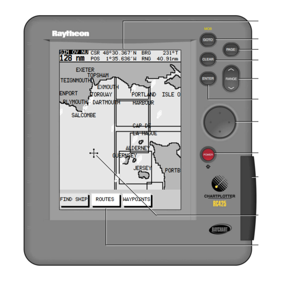
Cursor Primary Function Bar D4982_2 Figure 1-3: Raychart 425 Chartplotter Operating Controls Trackpad and Cursor The trackpad is used to move the cursor horizontally, vertically or diagonally. The cursor is the cross-hair symbol (+) which is used to select a position or item on the chart. -
Page 15: Dedicated Keys
Chapter 1: Overview Note: During many operations the cursor cannot be moved around the screen, eg. whilst a function bar is displayed, the cursor is used exclusive- ly for selection. In such cases, three rapid beeps indicate invalid action. Dedicated Keys These keys have fixed functions. -
Page 16: Database Lists
Raychart 425 Chartplotter Pop-Up Menus Pop-up menus usually provide various options. When a pop-up menu is on-screen, a set of associated functions is also displayed. Use the trackpad to select an option from the menu, then use the appropriate function to set the option, eg. the radius of the waypoint arrival alarm can be specified and the selected navigation data can be set on/off. -
Page 17: Chapter 2: Getting Started
Chapter 2: Getting Started 2.1 Introduction This chapter provides information and instructions to allow you to practice using the Raychart 425 Chartplotter. It is intended to help you become familiar with the controls before you start using the chartplotter for routine navigation. -
Page 18: Switching On/Off
Raychart 425 Chartplotter 2.2 Switching On/Off ➤ To turn the chartplotter display unit on, press the POWER key. The keys illuminate, the display unit beeps and the Raychart logo is displayed, followed by the following warning: WARNING THE ELECTRONIC CHART IS AN AID TO... -
Page 19: Chart Simulator
Chapter 2: Getting Started Figure 2-1: Lighting Controls The last-used control is highlighted in inverse video. 2. Press the trackpad left/right to select the LIGHTS function. 3. Press the trackpad top/bottom to increase or decrease the lighting to one of four levels. You can press and hold the trackpad to change the setting more rapidly. -
Page 20: Controlling The Display
Raychart 425 Chartplotter sired mode on power-up. Simulated data should never be used for nav- igational purposes. ➤ To view a chart image using simulated data: 1. Press the PAGE key to display the SET UP function bar (Figure 2-2):... - Page 21 Chapter 2: Getting Started From Chart Display Press PAGE to display Set Up functions PAGE SIM OV NU CSR 48°30.367'N 231°T 128 nm 1°35.636'W 40.91nm EXETER TOPSHAM TEIGNMOUTH EXMOUTH ENPORT TORQUAY PORTLAND ISLE O PLYMOUTH DARTMOUTH HARBOUR Press Press SALCOMBE PAGE PAGE CAP DE...
-
Page 22: Moving Around The Chart
Raychart 425 Chartplotter Moving Around the Chart You will normally operate the chartplotter with the chart showing your vessel’s current location. In the default North-Up orientation (shown in the status box at the top of the display), the vessel moves in relation to the screen. You will need to reposition the chart if your vessel moves out of the area currently displayed, or if you wish to examine or place waypoints in another area. -
Page 23: Changing The Chart Scale
Chapter 2: Getting Started • If Screen Amplifier is enabled, the vessel is positioned so as to increase screen forward visibility, see Chapter 4: Setting Up. 3. To release the cursor from homed mode press the trackpad to move the cursor away from the vessel’s current position. - Page 24 Raychart 425 Chartplotter 2. If further chart enlargement is available using the current chart card you can press the bottom of the RANGE key to zoom in again, reposi- tioning the cursor first if required. An area of further chart detail is indicated by a box around the area as shown in Figure 2-6.
-
Page 25: Using Navionics Nav-Chart Cards
To use the chartplotter as a navigation aid, charts with detailed information for the area you wish to navigate are required. The charts are available on Navionics Nav-Chart cards, each of which can store up to 20 charts in an electronic format, depending upon its memory storage capacity. -
Page 26: Removing A Nav-Chart Card
2-10 Raychart 425 Chartplotter D4706_2 Figure 2-7: Nav-Chart Card Insertion/Removal Removing a Nav-Chart card CAUTION: DO NOT use a metallic instrument, eg. a screwdriver or pliers, to aid removal, as doing so can cause irreparable damage. ➤ To remove a Nav-Chart card, refer to Figure 2-7: 1. -
Page 27: Chapter 3: Operation
Raychart 425. Safety The Raychart 425 makes it very easy to mark a waypoint and travel towards it. However, always check first that the route is safe. If using the chartplotter in combination with an autopilot connected via NMEA, the autopilot will normally prompt for confirmation before it steers the vessel towards the waypoint. -
Page 28: Placing A Waypoint
Raychart 425 Chartplotter Up menu, as described in Chapter 4. The waypoint is added to the waypoint list and named with the next available number. The edit functions can be used to change the symbol and name. When the cursor is positioned over a waypoint, the waypoint bearing and range are displayed. - Page 29 Chapter 3: Operation ii. Place the cursor in the required position on the chart and press ENTER to place the waypoint. The waypoint is added to the way- point list and named using the next available number. The waypoint functions remain displayed so that further way- points can be placed.
-
Page 30: Selecting A Waypoint
Raychart 425 Chartplotter Selecting a Waypoint Positioning the cursor over a waypoint selects that waypoint and accesses the WAYPOINT OPTIONS function bar. This enables you to GOTO (described in Section 3.4), edit (symbol, name, position), erase or move the waypoint. -
Page 31: Waypoint Data Display
Chapter 3: Operation The list details all waypoints. The selected waypoint is indicated by the highlight bar with its position; bearing and range are provided (if GPS fix available). 4. Use trackpad up/down to move through the list to highlight the required waypoint. - Page 32 Raychart 425 Chartplotter Figure 3-9: Edit Waypoint Function 4. To edit the waypoint name, select EDIT NAME . The NAME WAYPOINT window is displayed. 5. Use the trackpad to enter or edit the name as follows: • Use trackpad left/right to move the cursor to the character to be changed.
-
Page 33: Erasing Waypoints
Chapter 3: Operation Figure 3-13: Waypoint List Function Bar 4. Select EDIT WAYPOINT ; the waypoint edit functions are displayed (Figure 3-14): Figure 3-14: Waypoint Edit Functions 5. To edit the waypoint name, select EDIT NAME ; the cursor is placed in the name field of the selected waypoint. -
Page 34: Moving Waypoints
Raychart 425 Chartplotter ➤ To delete a waypoint using the waypoint list: 1. Select the waypoint from the waypoint list as previously described. The waypoint list function bar is displayed. 2. Use trackpad up/down to move through the list to highlight the required waypoint. - Page 35 Chapter 3: Operation When a route is created it becomes the current route and is displayed on-screen. The current route is maintained after power-off. Only one route can be current and is displayed (if it is in the field-of-view) as solid lines connecting waypoints.
-
Page 36: Creating A New Route
3-10 Raychart 425 Chartplotter Figure 3-18: Second Level Functions 4. Select MORE again to return to the first level functions. 5. Press CLEAR to return to chart mode. Creating a New Route Note: If there is a current route on screen, it is cleared when MAKE ROUTE is selected. -
Page 37: Saving The Current Route
Chapter 3: Operation 3-11 5. Press ENTER again. The next waypoint is placed and the dotted line changes to a solid line. Note: If the waypoint was placed incorrectly, it can be deleted by press- ing CLEAR . Successive waypoints can be deleted in this way. 6. -
Page 38: Clearing The Current Route From The Screen
3-12 Raychart 425 Chartplotter 4. Press ENTER to save the route. Press ENTER again (in response to the prompt) to name the route or CLEAR to save as the default ROUTE XX , where XX is the next available number. -
Page 39: Displaying Route Leg And Waypoint Information
Chapter 3: Operation 3-13 Figure 3-21: Route List Display 2. Select SHOW ROUTE . The route list is removed and the selected route is shown on screen as the current route. Displaying Route Leg and Waypoint Information ➤ To display information about a route leg, move the cursor over the leg until its data is displayed in the status bar at the top of the screen (Figure 3-22). -
Page 40: Erasing Or (Re)Naming A Route
3-14 Raychart 425 Chartplotter Erasing or (re)Naming a Route A route or can be deleted or re-named via the Route List. When deleting a route, you are prompted to confirm. ➤ To select a route to delete: 1. Select ROUTES , followed by MORE , then ROUTE LIST . The route list is displayed with the selected route highlighted. - Page 41 Chapter 3: Operation 3-15 1. Select EDIT ROUTE and press ENTER ; the PLACE WAYPOINT function is shown as above (see Figure 3-19). 2. Add waypoint(s) to the route by moving the cursor and pressing ENTER in the same way as the route was first created. 3.
-
Page 42: Following Routes And Going To Target Points
3-16 Raychart 425 Chartplotter ➤ To remove a waypoint from the route using the cursor: 1. Place the cursor over the waypoint; see Selecting a Waypoint on page 3-4. 2. Select WAYPOINT OPTIONS ; the Waypoint functions are displayed. 3. Select REMOVE WAYPOINT ; the waypoint is removed from the route and the remaining waypoints in the current route are renumbered accordingly. -
Page 43: Follow A Route
Chapter 3: Operation 3-17 Figure 3-28: Second Level GOTO Functions 3. Select MORE to return to the first level functions. 4. Press CLEAR to return to the chart screen. Note: The functions differ if a FOLLOW or GOTO is already in progress (see Stop Follow or Stop Goto on page 3-23). -
Page 44: Target Point Arrival
3-18 Raychart 425 Chartplotter ➤ To follow the reversed route: 3. Press the GOTO key. The Goto/Follow functions are displayed. 4. Press FOLLOW ROUTE . The vessel’s current position becomes the origin and the first waypoint in the reversed route becomes the target waypoint. The function bar is removed. -
Page 45: Join A Route
Chapter 3: Operation 3-19 Join a Route ➤ To start following the current route from a selected waypoint: 1. Move the cursor over a route waypoint until the WAYPOINT OPTIONS function is displayed (Figure 3-29): Figure 3-29: Route Options Function 2. -
Page 46: Going To An Individual Target
3-20 Raychart 425 Chartplotter ➤ To restart XTE: 1. Press the GOTO key. If following a route, the following functions are displayed (Figure 3-32): STOP RESTART WAYPOINT FOLLOW ADVANCE D4688_1 Figure 3-32: GOTO Options (1) If a GOTO is in progress, the following functions are displayed... -
Page 47: Go To Cursor
Chapter 3: Operation 3-21 ii. Press the GOTO key to display the waypoint options and select GOTO WAYPOINT ; the waypoint list appears. Use the cursor to select the required waypoint (Figure 3-36): SIM OV NU Figure 3-36: Waypoint List Alternatively, a waypoint can be selected from the Waypoint List as described in Section 3.2. - Page 48 3-22 Raychart 425 Chartplotter ➤ To navigate directly to the current cursor position: 1. Press the GOTO key and select GOTO CURSOR . The GOTO CURSOR function now has help text appended to it (Figure 3-37): GOTO MOVE CURSOR, "ENTER" TO START CURSOR GOTO CURSOR, "CLEAR"...
-
Page 49: Stop Follow Or Stop Goto
Chapter 3: Operation 3-23 2. Use trackpad up/down to select the required destination and press ENTER to start the GoTo, or CLEAR to cancel the operation. The operation is conducted in the same manner as for GOTO PORT above. Stop Follow or Stop Goto ➤... -
Page 50: Cdi Display
3-24 Raychart 425 Chartplotter ➤ To change the display mode: 1. Press the PAGE key to show the SET UP functions with SYSTEM SET UP highlighted (Figure 3-39): SYSTEM CHART TRACK SETUP SETUP SETUP SETUP D4699_1 Figure 3-39: Setup Function Bar 2. -
Page 51: Bdi Display
Chapter 3: Operation 3-25 At waypoint ranges greater than 4nm, the symbol remains at the top of the screen. As the waypoint range falls below 4nm, the symbol moves down the centre line. The checkered pattern moves down the screen to simulate movement when SOG is greater than 2 knots. -
Page 52: Waypoint Data
3-26 Raychart 425 Chartplotter The line to the waypoint symbol is shown at an angle equal to the difference between the COG and the Bearing to Waypoint. The range scale automatically scales for distance. The ranges shown are 1nm, 4nm, 20nm, 40nm, 100nm, 200nm, 400nm, 1000nm, 2000nm, 4000nm. -
Page 53: Navigation Data
Chapter 3: Operation 3-27 The WAYPOINT field shows the name of the waypoint. If the waypoint is part of a route then the title field includes the waypoint index in the route. If there is no target waypoint the text indicates NO WAYPOINT and all waypoint data is shown as dashes, one per character. -
Page 54: Time/Date Data
3-28 Raychart 425 Chartplotter POSITION 50°45.252 N 1°06.000 W (c) COG 230° T SOG 6.8 Kts WAYPOINT BRG 234° T RNG 2.4 nm TIME 14:32 12/12/99 STEER STARBOARD D4703_2 Figure 3-43: Navigation Data Display Textual data provides Position, SOG, COG, Bearing and Range to waypoint, Time, Fix status and the XTE indicator. - Page 55 Chapter 3: Operation 3-29 SUNRISE 06.23 SUNSET 21.34 TODAY AT POSITION (USER SELECTED) 50°45 .000 N 001°06 .000 W (c) TIME 12:34 DATE 26/01/99 (WAYPOINT) 13:37 26/01/99 (WAYPOINT) 01:03 (ROUTE) 14:32 27/01/99 (ROUTE) 34:03 STEER STARBOARD D4704-1 Figure 3-44: Time/Date Data Display Textual data provides Sunrise and Sunset time, Current Time/ Date, Waypoint and Route arrival times plus the XTE indicator.
-
Page 56: Transferring Waypoints And Routes
3-30 Raychart 425 Chartplotter All data is based on the SOG towards the current target. If the SOG is negative, or data is not available, these fields are replaced with dashes, one per character. ➤ To display Sunrise/Sunset information for a different date: 1. - Page 57 Chapter 3: Operation 3-31 The RECEIVE WAYPOINTS function adds waypoints and routes received via NMEA to the Waypoint List and Route List. Note: Where multiple waypoints have the same position, the last way- point sent is the only one included in the Waypoint List. ➤...
-
Page 58: Using Tracks
3-32 Raychart 425 Chartplotter ➤ To receive waypoints and route lists: 1. Display the Waypoint List as previously described, then select WPT/ROUTE TRANSFER . 2. Select RECEIVE WAYPOINTS and press ENTER ; the text changes to STOP RECEIVING and remains selected. -
Page 59: Setting Up A Track
Chapter 3: Operation 3-33 Figure 3-51: Track Set Up Options The following instructions assume that the track functions are displayed. Setting up a Track Use the track functions to switch the track on and to specify the interval at which track points are placed. The time interval between track points can be set to 1s, 10s, 30s, 1min, 10min or 30 minutes. -
Page 60: Clearing The Current Track
3-34 Raychart 425 Chartplotter 33 min 10 s 5 hrs, 30 min 30 s 16 hrs, 40 min 1 min 33 hrs, 20 min 10 min 13 days, 21 hrs, 20 min 41 days, 16 hrs 30 min TRACK TIME 0.05 nm... -
Page 61: Smartroute
Chapter 3: Operation 3-35 SmartRoute SmartRoute enables the latest track to be converted to a route. ➤ To convert a track to a route: 1. Select MAKE INTO ROUTE and press ENTER . The current track is converted to a new route, with the most recently placed track point as the start of the route, ie. -
Page 62: Tide Information
3-36 Raychart 425 Chartplotter OTHER INFORMATION FUEL GENERAL SERVICES FIRST AID OTHER UTILITIES ON THE PIER WATER REPAIR SERVICES D4708_1 Figure 3-54: Available Port Services 3. Use the trackpad to select the required service and press ENTER to display further details (Figure 3-55):... - Page 63 Chapter 3: Operation 3-37 displayed in an object information pop-up box. Soft keys enable Sun/Moon Data and Previous/Next Day information to be displayed. Tidal Height ➤ To obtain Tide Height Data: 1. Place the cursor over a Tide Height symbol The Tidal Heights soft key and help text appear (Figure 3-56).
- Page 64 3-38 Raychart 425 Chartplotter The ‘Port Name’ is that supplied by the Nav-Chart cartridge. The Tidal Height graph is automatically scaled. The cursor, represented by a dashed line, can be moved along the horizontal axis by means of the Trackpad. A CURSOR data box below the graph shows corresponding TIME and HEIGHT .
- Page 65 Chapter 3: Operation 3-39 NANTUCKET TIDAL HEIGHT 1.31 1.06 0.81 0.57 0.33 0.08 -0.15 TIME TODAY RISES 4:18 DATE:13/ 7/99 SETS 19:13 TIME:04:13:56 MOON MOON PHASE RISES 4:50 FIRST QRT SETS 19:45 IN 7 DAYS TIDAL PREVIOUS NEXT TODAY HEIGHTS D4976_1 Figure 3-59: Tidal Heights &...
- Page 66 3-40 Raychart 425 Chartplotter NANTUCKET HARBOR TIDAL CURRENT 1.43 0.90 0.36 -0.16 -0.69 -1.22 -1.75 TIME CURSOR TODAY TIME 4:30 DATE: 13/ 7/99 350° TIME: 01:15:10 DRIFT 1.1Kts TIME DRIFT SLACK 3:21 350° 1.8Kts 12:02 8:02 171° 1.4kts FLOOD 5:56 15:59 350°...
- Page 67 Chapter 3: Operation 3-41 SUN/MOON PREVIOUS TODAY NEXT DATA D4975_1 Figure 3-62: Sun/Moon Data Soft Keys 2. Using trackpad left/right, select PREVIOUS DAY or NEXT DAY soft key; press ENTER the appropriate number of times to select the required Date. 3.
-
Page 68: Man Overboard (Mob)
3-42 Raychart 425 Chartplotter 3.9 Man Overboard (MOB) If a person or object is lost overboard, and you need to return to the location, use the Man Overboard (MOB) function. Note: To obtain MOB position, a valid GPS fix must be available. -
Page 69: Alarms
Chapter 3: Operation 3-43 3.10Alarms The chartplotter reports the following alarms (Table 3-1 ): Table 3-1: Alarm Settings Alarm Indicates Arrival The vessel has arrived at the active waypoint: it has either reached the arrival circle (the radius of which is specified) or, has reached its closest point of approach (defined by a line passing through the waypoint and perpendicular to the track). - Page 70 3-44 Raychart 425 Chartplotter...
-
Page 71: Chapter 4: Setting Up
Chapter 4: Setting Up Chapter 4: Setting Up 4.1 Introduction When you have installed your system and are familiar with its basic operation, you may wish to set it up to operate according to your requirements and display information according to your preferences. This is achieved using the function controls which are displayed when the PAGE key is pressed. - Page 72 Raychart 425 Chartplotter Figure 4-2: System Set Up Menu 3. Use trackpad up/down to move the highlight up or down the list. 4. When the required parameter is highlighted, use trackpad left/right to step through the settings. 5. When the required values have been chosen, press ENTER to imple- ment the change and return to the set up function bar.
-
Page 73: Bearing Mode
Chapter 4: Setting Up Table 4-2: System Menu Options (Continued) Factory Menu Item Options Default New Setting DEPTH UNITS METRES METRES FEET FATHOMS VARIATION 30°W to 30°E (1° steps) 0.0°E DATE FORMAT DD/MM/YY or MM/DD/YY DD/MM/YY TIME OFFSET UTC or local offset value up to 13 hours in 1 hour steps LANGUAGE... -
Page 74: Date Format
Simulator The simulator allows operation of the Raychart 425 without data from external sources. The options are ON or OFF . When ON is selected the simulator generates position, SOG and COG data and uses the simulated data instead of any real data. -
Page 75: Simulated Cog
Chapter 4: Setting Up Simulated COG Use horizontal movements of the trackpad to adjust the value of COG which is adjustable in 1° intervals from 000° to 359°. It wraps around from 000 to 359 and from 359 to 000. The Default value is zero and the selected value is retained on power down. - Page 76 Raychart 425 Chartplotter 3. Use trackpad up/down to highlight the required parameter, then use trackpad left/right to select the required setting. 4. When the required values have been set, press ENTER to clear the menu and return to the set up function bar.
-
Page 77: Orientation
Chapter 4: Setting Up Table 4-3: Chart Setup Parameters (Continued) Factory Parameter Options Default New Setting DEPTH CONTOURS OFF/ON DEPTH CONTOURS OFF/ON >20M POSITION CALIBRA- OFF/ON/SET CAL TION Orientation The chart orientation is normally North Up, but can be changed to Course Up or Head Up. -
Page 78: Waypoint Symbol
Raychart 425 Chartplotter Waypoint Symbol This option allows selection of the symbol for waypoint display. The selected symbol is used for subsequent waypoints. Existing waypoints are not affected. The selected symbol is retained when the unit switched off. Autozoom When autozoom is enabled, commencing any navigation function or selecting FIND SHIP activates Autozoom. -
Page 79: Xte Alarm
Chapter 4: Setting Up To silence the alarm, press any key. This removes the warning and resets the distance, ie. the alarm will not sound again unless the vessel moves the selected distance from its position (at the time that the alarm was silenced). -
Page 80: Gps Setup
4-10 Raychart 425 Chartplotter ➤ To perform position calibration: 1. Using horizontal trackpad movements, select SET CAL . The menu is removed and a single function and help text are shown (Figure 4-5): D4713_ Figure 4-5: Set Position Function 2. Using the trackpad, set the value of offset required. The distance and bearing of cursor from vessel is displayed in the Status Bar as BRG and RNG . - Page 81 Chapter 4: Setting Up 4-11 SD-FIX D4714_2 SD-GPS "ENTER" FOR SD-GPS SETUP MENU SET UP "CLEAR" TO QUIT D4995_1 Figure 4-7: GPS Status Screen and Soft Key The GPS STATUS screen provides, for each tracked satellite, the satellite number, a graphical signal strength bar, status, azimuth angle and its elevation angle from your vessel.
- Page 82 4-12 Raychart 425 Chartplotter SD GPS SET UP SD MODE ENABLED SATELLITE SELECT AUTO SD SATELLITE NAME XXXX SIGNAL STRENGTH 50dB AZIMUTH 234° ELEVATION 23° D4996_1 Figure 4-8: SD GPS SET UP Menu 2. Using vertical trackpad movements, select SD MODE .
-
Page 83: Chapter 5: Installation
This chapter provides instructions to assist in planning the installation of the Raychart 425 Chartplotter aboard your vessel. Note: If you wish to practice using the Raychart 425 before installation, you can connect it, via a 1A quick blow fuse, to a 12VDC power supply and operate it using the simulator mode, as described in Chapter 2:Get- ting Started. -
Page 84: Suppression Ferrites
Raytheon unit. 5.2 Unpacking and Inspecting the Components Unpack your Raychart 425 Chartplotter carefully. Retain the carton and packing materials in the event that you need to return the unit for service. Referring to Table 5-1 , check that you have all the correct system components. -
Page 85: Items Missing
Chapter 5: Installation Table 5-1:System Parts and Accessories (Continued) Item Part # Panel Mount Kit* E35006 Trunnion Mount Kit E35005 Power Cable R38024 GPS Extension Cable* E35003 Owner’s Handbook 81172 Bridge Card 86055 * Optional Accessory. Items Missing? If any one (or more) of the above items is missing or damaged, please contact your Raytheon dealer or our Product Support Department to obtain replacement parts. -
Page 86: Surface Mounting
Raychart 425 Chartplotter When planning the location for the unit, consider finding a convenient pathway for running the interconnecting cable between the GPS Receiver and the display unit or to the rest of an integrated system. Ideally the cable should be run such that it is hidden from view and, if possible, be in a direct path to the point of connection. -
Page 87: Pole Mounting
Chapter 5: Installation Top view Underside view D4725_1 Figure 5-2: Surface Mounting Arrangement Pole Mounting Refer to Figure 5-3: 1. Screw the pole mount base to a suitable pole or rail mount bracket, having an industry standard 1in 14TPI thread, until secure. 2. -
Page 88: Installing The Chartplotter
D4726-1 Figure 5-3: Pole Mounting Arrangement 5.3 Installing the Chartplotter When planning the installation of your Raychart 425, the following points should be considered to ensure reliable and trouble free operation: • Convenience: The unit should be installed in a convenient position where it can be viewed straight on or with a viewing angle of less than 35°. - Page 89 Chapter 5: Installation • Interference: The selected location should be far enough away from devices that may cause interference, such as motors and generators (see the EMC guidelines earlier in this section). • Power Source: The unit should be located near a DC power source. The power cable supplied is 1.5m, but a longer cable can be used if required.
-
Page 90: Trunnion (Yoke) Mounting
35 mm (1.38 in) (1.38 in) 122 mm (4.8 in) D4721-1 Figure 5-4: Raychart 425 Dimensions Trunnion (yoke) Mounting The display unit can be conveniently mounted on a dash area, chart table, bulkhead or deckhead. Trunnion mount the unit as follows:... -
Page 91: Panel Mounting
Chapter 5: Installation 1. Loosen the trunnion knobs and remove the trunnion from the display unit. 2. Mark the locations of the trunnion screw holes on the mounting sur- face. 3. Use the screws supplied to fix the trunnion at the marked locations. 4. -
Page 92: Cable Running
5-10 Raychart 425 Chartplotter D4722_1 Figure 5-5: Raychart 425 Panel Mounting Arrangement 5.4 Cable Running Introduction The minimum requirements are a power cable and a connection from the Raystar 120 GPS Receiver. Additional cables will be required if connecting to other equipment. -
Page 93: Connectors
Chapter 5: Installation 5-11 Connectors GPS Connector The GPS connector provides power and data connections to the Raystar 120 GPS Receiver using the attached 33ft (10m) cable terminated in a moulded 6-pin connector. ➤ Connect the GPS Receiver as follows: 1. - Page 94 5-12 Raychart 425 Chartplotter suitable connector block to connect to the extension cable. The supplied power cable cores have a cross-section of 2.0mm (15 AWG). Longer power cable runs may require larger wire gauges to minimize any voltage drop in the cable. In order to determine the correct supply cable size if the power cable must be extended, estimate the length of cable between the vessel’s main power source and the connector block, then...
-
Page 95: System Check And Initial Switch On
Chapter 5: Installation 5-13 3. Use a suitable junction box to connect to NMEA equipment if required. 4. Cut any unused cores short or insulate and tape back. Note: If the power connections are accidentally reversed, the system will not function. Use a voltmeter to check that the input power leads are con- nected with the correct polarity. -
Page 96: Checking Chartplotter Operation
1. Press the trackpad left/right, up/down and check cursor movement and normal scrolling action. 2. Insert a Navionics Nav-chart card for the area of your vessel. ® Use the RANGE key to zoom-in and check that the new chart car- tridge data is displayed. -
Page 97: Chapter 6: Maintenance & Fault Finding
Chapter 6: Maintenance & Fault Finding Chapter 6: Maintenance & Fault Finding This chapter provides information on routine maintenance and on possible causes of problems you may experience with your Raychart 425 Chartplotter and/or its associated Raystar 120 Receiver. 6.1 Maintenance... -
Page 98: Resetting The System
Raychart 425 Chartplotter installation instructions, to enable you to ensure minimum interaction between different items of equipment, ie. ensure optimum Electromagnetic Compatibility (EMC). Always report any EMC-related problem to your nearest Raytheon dealer. We use such information to improve our quality standards. -
Page 99: Fault Finding
Chapter 6: Maintenance & Fault Finding Fault Finding As a guide to problem solving, common problems and their possible causes are detailed in Table 6-1. Table 6-1:Fault Finding Guide Problem Correction Unit does not function 1. Make sure that the power supply cable is sound and that all connections are tight and free from corrosion. - Page 100 Raychart 425 Chartplotter...
-
Page 101: Appendix A: Raychart 425 Specification
Appendix A: Raychart 425 Specification Appendix A: Raychart 425 Specification Conforms to 89/336/EEC(EMC), EN60945:1997 Compliant Size 184mm (7.3in) x 168mm (6.7in) x 75mm (3in), excluding trun- nion Weight 0.75 kg (1.65 lb) Environmental Waterproofing To CFR46; suitable for external mounting Temp Range - Operating: -10°C to 70°C... - Page 102 Raychart 425 Chartplotter Memory Capacity: Waypoints: 500 max (20 routes of up to 50 way- points) Track history: 2000 points Protection: Built in dealer replaceable Lithium battery giving 3 to 5 years usage...
-
Page 103: Appendix B: Raystar 120 Specification
Appendix B: Raystar 120 Specification Appendix B: Raystar 120 Specification Feature Details Receiver type: 12 Parallel channels Frequency: 1575.42 MHz ±1 MHz (C/A code), L1 Sensitivity: -130dBm Signal acquisition: Automatic Time to first fix: 2.5 minutes maximum, typically <40 seconds Position accuracy: 15m RMS. - Page 104 Raychart 425 Chartplotter...
-
Page 105: Appendix C: Nmea Data
Appendix C: NMEA Data Appendix C: NMEA Data Connector Received Transmitted POWER/NMEA GGA, GSV, GSA, GLL, GGA, GSV, GSA, VTG, MSS, WPL, RTE, RMC GLL,VTG, WPL, RTE, XTE, APB, BWR, RMB GGA, GSV, GSA, GLL,VTG, PRAYA... - Page 106 Raychart 425 Chartplotter...
-
Page 107: Appendix D: List Of Abbreviations
Appendix D: List of Abbreviations Appendix D: List of Abbreviations Bearing Deviation Indicator Bearing To Waypoint Course Deviation Indicator Course Over Ground. The actual direction of your vessel’s movement over the ground. dGPS Differential Global Positioning System Distance To Go Electro-Magnetic Compatibility Estimated Time of Arrival Global Positioning System... - Page 108 Raychart 425 Chartplotter...
- Page 109 This equipment uses certain elements of software supplied to Raytheon by SiRF Tech- nology Inc., to which the following licence agreement applies. Please read it carefully. SiRF LICENSE AGREEMENT IMPORTANT - READ CAREFULLY: This is a legal agreement (the “Agreement”) between SiRF Technology Incorporated, which has offices at 3970 Freedom Circle, Santa Clara, California 95054 (“SiRF”) and you.
-
Page 111: Gps Receiver Mounting Template
Installation Templates 19mm (0.75") dia. 36mm (1.4in) for NMEA plug 18mm (0.7in) 6mm (0.25") dia. 6mm (0.25") dia. 2 positions Cable Exit Channel for cable only D4194-1 GPS Receiver Mounting Template Note: Access to the underside of the mounting surface must be available to allow for secure fixing. - Page 112 Raychart 425 Chartplotter...