Advertisement
Quick Links
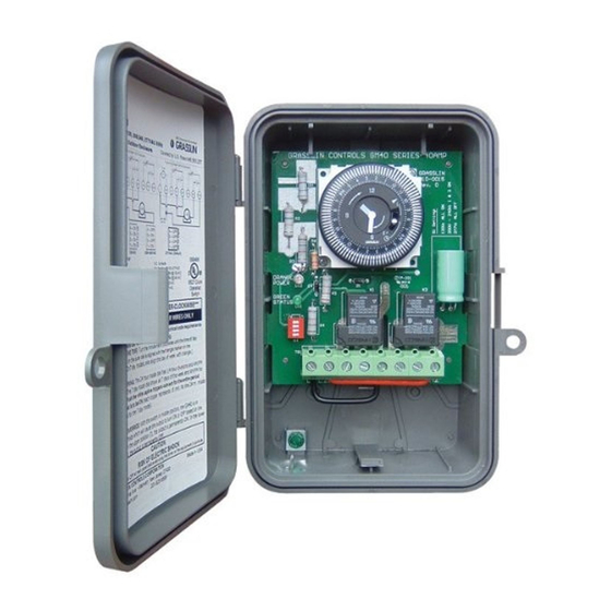
NEMA 3R Enclosure
File #E83486
Covered by U.S. Patent #6,563,2371.
Bracket
Mount with
Dimensions
Diagram not to scale.
All dimensions in inches.
ELECTRICAL RATINGS:
N.O. Contacts:
40A Resistive @ 120~277VAC
1HP, 16FLA, 90LRA @ 120VAC
2HP, 12FLA, 52LRA @ 208~277VAC
30A Ballast @ 120VAC
20A Ballast @ 277VAC
15A Tungsten @ 120VAC
300VA Pilot Duty 120~240VAC
N.C. Contacts:
30A Resistive @ 120~277VAC
1HP, 12FLA, 30LRA @ 120VAC
2HP, 10FLA, 30LRA @ 240VAC
2A Tungsten @ 120VAC
10A Ballast @ 277VAC
WIRING CONNECTIONS:
Screw box lug terminals
ENVIRONMENTAL RATINGS:
Operating Temperature Range:
–40°F to 131°F (–40°C to 55°C)
Operating Humidity: 0 to 95% non-condensing
ENCLOSURE DIMENSIONS:
8.795" x 6.631" x 2.935" (H x W x D)
SHIPPING WEIGHT: 2 lbs.
GM40 General Purpose
Multi-Voltage Commercial
Time Switch
INSTALLATION
1. Open door and then remove interior protective cover by releasing spring clip on bottom.
2. Remove timer mechanism by releasing spring clip on bottom.
3. Select knockouts to be used. Remove inner 1/2" knockout by inserting a screwdriver in
the slot and carefully punch knockout loose. Remove slug. If 3/4" knockout is required,
remove the outer ring with pliers after removing the 1/2" knockout. Smooth edges with
knife if necessary.
4. Place enclosure in desired mounting location and mark the three mounting holes (refer to
diagram). Start by placing set screw on top and attaching enclosure over keyhole; then
screw in remaining two screws on bottom.
5. Connect conduit hubs to conduit before connecting the hubs to the enclosure. After
inserting hubs into enclosure, carefully tighten hub lock nut. Do not over-torque.
6. Verify input voltage selection. Refer to DIP switch diagram for desired input voltage.
7. Wire in accordance with National and Local Codes (see wiring diagrams).
8. Grounding: Terminate all ground wires to ground lug on bottom of enclosure.
9. Replace interior protective cover.
Note: For outdoor locations, raintight or wet location conduit hubs that comply with require-
ments of UL 514B (standard for fittings for conduit and outlet boxes) must be used.
INPUT VOLTAGE DIP SWITCH SETTING:
1. Do not apply power to the GM40 prior to setting correct Input Voltage DIP switch.
2. Determine the input voltage which will be applied to the GM40 (i.e. L1 and L2/N terminals,
see wiring diagrams).
3. Set the DIP Switch according to the diagram below.
120VAC
208~240VAC
4
ON
3
ON
2
ON
1
ON
NOTE: Unit is shipped with DIP Switches set for 277VAC Input Voltage.
CAUTION: Do not check circuits by "sparking" wires to terminals. Damage to
the timer may result.
Timer Mechanism
Interior
Protective
Cover
Step 1
277VAC (Default)
4
OFF
4
OFF
3
ON
3
OFF
2
OFF
2
OFF
1
ON
1
OFF
2-1/2"
Step 2
Ground Lug
6-1/8"
Advertisement

Related Manuals for Intermatic TimeMaster GM40


Summary of Contents for Intermatic TimeMaster GM40
- Page 1 GM40 General Purpose Multi-Voltage Commercial Time Switch INSTALLATION 1. Open door and then remove interior protective cover by releasing spring clip on bottom. 2. Remove timer mechanism by releasing spring clip on bottom. 3. Select knockouts to be used. Remove inner 1/2” knockout by inserting a screwdriver in the slot and carefully punch knockout loose.
- Page 2 Real-Time Clock Face NO TOOLS REQUIRED! New Compact Our “GUTS” simply snap VALOX ® NEMA 3R into existing Grasslin or Outdoor Enclosure Intermatic enclosures Replaces All Metal Enclosures 40 Amp Rated Large Screw Contacts Terminals for Easy Wiring #8 AWG Moisture Resistant...
- Page 3 GM40 TERMINAL DESIGNATIONS Note: GM40 is shipped with pre- TIMER installed jumper wires (L1 to COM and L2/N to COM2). In applica- tions requiring a “DRY” non ener- gized contact, remove jumpers as shown. COM2 Normally Open Normally Open (Dry Contact) (Dry Contact) Normally Closed Normally Closed...
- Page 4 The GM40 Series printed circuit board assembly will fit into all Intermatic enclosures except the T7000 and T5000 Series. Install GM40-M into Intermatic enclosure in the same manner as the Intermatic mechanism was previously installed. Intermatic, Inc. 7777 Winn Road Spring Grove, IL 60081 www.intermatic.com...