Table of Contents
Advertisement
Quick Links
Advertisement
Table of Contents
Troubleshooting

Related Manuals for Doosan DV11


Summary of Contents for Doosan DV11
- Page 1 65.99897-8098A Operation and Maintenance Manual Diesel Engine DV11 PS-MMG0717-E1B...
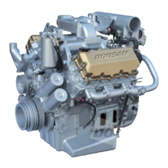
- Page 2 DV11 Operation and Maintenance FOREWORD This maintenance manual is designed to serve as a reference for DOOSAN Infracore (here after DOOSAN’s) customers and distributors who wish to gain basic product knowledge on DOOSAN's DV11 Diesel engine. This economical and high-performance diesel engine (6 cylinders, 4 strokes, in-line, direct injection type) has been so designed and manufactured to be used for the overland transport or industrial purpose.
-
Page 3: Table Of Contents
DV11 Operation and Maintenance CONTENTS 1. Safety regulations & engine specifications 1.1. Safety regulations 1.2. Engine specifications 1.3. Engine power 1.4. Performance curve 1.5. Engine assembly 2. Technical information 2.1. Engine model and serial number 2.2. Diagnostic tool (SCAN-200) 2.3. Engine characteristic 2.4. - Page 4 Before putting the engine into operation for the first time, read the operating instructions carefully and familiarize yourself with the “critical” points. If you are unsure, ask your DOOSAN representative or service man. For reason of safety we recommend you attach a notice to the door of the...
- Page 5 DV11 Operation and Maintenance (2) Maintenance and care Always carry out maintenance work when the engine is switched off. If the engine has to be maintained while it is running, e.g. changing the elements of change-over filters, remember that there is a risk of scalding. Do not get too close to rotating parts.
-
Page 6: Safety Regulations
(2) If faults occur, find the cause immediately and have it eliminated in order to prevent more serious of damage. (3) Use only genuine DOOSAN spare parts. DOOSAN will accept no responsibility for damage resulting from the installation of other parts which are supposedly "just as good”. - Page 7 DV11 Operation and Maintenance Do not let the raw water pump run dry. If there is a risk of frost, drain the pump when the engine is switched off. 1.1.4. To prevent pollution (1) Engine oil, filter elements, fuel filters Take old oil only to an oil collection point.
- Page 8 4. The use of proper tools and special tools where specified is important to efficient and reliable service operation. 5. Use genuine DOOSAN parts necessarily. 6. Used cotter pins, gaskets, O-rings, oil seals, lock washer and self-lock nuts should be discarded and new ones should be prepared for installation as normal function of the parts can not be maintained if these parts are reused.
-
Page 9: Engine Specifications
DV11 Operation and Maintenance 1.2. Engine Specifications Engine model DV11 Items Water-cooled, 4 cycle V-type 90°, Turbo charged & Engine type intercooled Combustion chamber type Direct injection type Cylinder liner type Wet type Timing gear system Gear driven type No. of piston ring 2 compression ring, 1 oil ring No. - Page 10 DV11 Operation and Maintenance Engine model DV11 Items Wax pallet type (79 ∼ 94 °C) Type 83 °C Open at (°C) Thermostat 95 °C Open wide at (°C) Valve lift (mm) Water temperature indicator Water temperature sensor mounted Type Water cooled...
-
Page 11: Engine Power
DV11 Operation and Maintenance 1.3. Engine Power tolerance : ±5% Performance Engine model Remark Power Torque Low idle High idle Suffix Model (PS / rpm) (kg.m / rpm) (rpm) (rpm) EUJBA W/ Jake brake 380 / 1,800 173 / 1,200 2,120↓... - Page 12 DV11 Operation and Maintenance Engine Performance Curve 1.4. 1.4.1. Performance curve (340PS) Revolution (rpm) Performance ISO 1585 (SAE J1349) Output (max.) 250 kW (340PS) / 1,800 rpm Torque (max) 1,423 N.m (145 kg.m) / 1,200 rpm Fuel consumption (min.) 203 g/kW.h (149 g / PS.h) Safety regulations &...
- Page 13 DV11 Operation and Maintenance 1.4.2. Performance curve (360PS) Revolution (rpm) Performance ISO 1585 (SAE J1349) Output (max.) 265 kW (360PS) / 1,800 rpm Torque (max) 1,570 N.m (160 kg.m) / 1,200 rpm Fuel consumption (min.) 203 g/kW.h (149 g / PS.h) Safety regulations &...
-
Page 14: Performance Curve
DV11 Operation and Maintenance 1.4.3. Performance curve (380PS) Revolution (rpm) Performance ISO 1585 (SAE J1349) Output (max.) 280 kW (380PS) / 1,800 rpm Torque (max) 1,570 N.m (160 kg.m) / 1,200 rpm Fuel consumption (min.) 203 g/kW.h (149 g / PS.h) Safety regulations &... - Page 15 DV11 Operation and Maintenance 1.4.4. Performance curve (400PS) Revolution (rpm) Performance ISO 1585 (SAE J1349) Output (max.) 294 kW (400PS) / 1,800 rpm Torque (max) 1,697 N.m (173 kg.m) / 1,200 rpm Fuel consumption (min.) 203 g/kW.h (149 g / PS.h) Safety regulations &...
- Page 16 DV11 Operation and Maintenance 1.4.5. Performance curve (420PS) Revolution (rpm) Performance ISO 1585 (SAE J1349) Output (max.) 309 kW (420PS) / 1,800 rpm Torque (max) 1,834 N.m (187 kg.m) / 1,200 rpm Fuel consumption (min.) 203 g/kW.h (149 g / PS.h) Safety regulations &...
- Page 17 DV11 Operation and Maintenance 1.5. Engine Assembly 1.5.1. Engine sectional view (longitudinal) Vibration damper Power steering pump Thermostat Oil seal Exhaust valve Fly wheel Push rod Crank shaft Tappet Oil pump Air compressor Safety regulations & specifications Printed in Mar. 2005 PS-MMA0608-E1A...
- Page 18 DV11 Operation and Maintenance 1.5.2. Engine sectional view (cross) Starting motor Injector Oil cooler Oil spray nozzle Cylinder block Connecting rod Cylinder head Electric control unit (E.C.U) Engine brake Oil drain plug Fuel high pressure pump Oil suction pipe Common rail Safety regulations &...
-
Page 19: Engine Assembly
DV11 Operation and Maintenance Engine assembly (Bus engine) 1.5.3. Crank shaft pulley Exhaust manifold Air pipe Oil filter Mounting bracket (rear) ( turbocharger to intercooler Water pump pulley Flywheel housing Air heater Idle pulley Mounting bracket (front) Air pipe Water outlet... - Page 20 DV11 Operation and Maintenance Engine assembly (Truck engine) 1.5.4. Power steering pump Fan guide 2nd fuel filter Air compressor Cooling fan Air pipe Exhaust outlet Starter (Air filter to intake manifold) Turbo charger Exhaust manifold Breather Oil filler cap Water inlet...
-
Page 21: Engine Model And Serial Number
They are also referred to as engine model and serial number because of their location. Engine serial No. (example 1 : DV11) DV11 5 00001 BA Engine model suffix (EUJBA) Serial no. Production year (2005) Engine model Engine serial No. - Page 22 2.3. Engine Character DOOSAN ‘s DV11 diesel engine apply the over head valve and the turbocharger, is the electric control engine of the air cooling type by the cooling fan. The fuel is stored under pressure in the high-pressure accumulator (the "Common Rail") ready for injection.
- Page 23 DV11 Operation and Maintenance 2.3.1. Cylinder block The cylinder block is a single piece of alloy cast iron. To increase its stiffness, it is extended to a level below the crankshaft center line. The engine has replaceable wet cylinder liners and individual cylinder heads.
- Page 24 DV11 Operation and Maintenance 2.3.4. Common rail system Pressure generation and fuel injection are completely decoupled from each other in the "Common Rail" fuel injection system. The injection pressure is generated independent of engine speed and injected fuel quantity stored in the ECU.
-
Page 25: Technical Information
DV11 Operation and Maintenance 2.3.5. Engine timing Camshaft, oil pump, air compressor, steering pump, and fuel high pressure pump are driven by a gear train arranged at the inside of flywheel housing. High pressure pump Power take off(PTO) gear gear (Z=24) - Page 26 DV11 Operation and Maintenance 2.3.7. Lubrication system The engine is equipped with force-feed lubrication. The pressure is produced by a gear pump whose drive gear is in direct mesh with the crankshaft gear at the flywheel end. The oil pump draws the oil from the oil sump and delivers it through the oil cooler...
- Page 27 DV11 Operation and Maintenance 2.3.8. Engine oil Check oil level with the oil level gauge and replenish if necessary. Check the oil level with the engine cooled. If the engine is warm, allow time for 5 ∼ 10 minutes for oil drain into the crankcase before checking oil level. The oil level must be between Max.
- Page 28 DV11 Operation and Maintenance Engine oil viscosity – ambient temperature Ambient temperature 2.3.9. Oil filter Check for oil pressure and oil leaks, and repair or replace the oil filter if necessary. Change filter cartridge simultaneously every replacement of engine oil.
- Page 29 DV11 Operation and Maintenance - Adjust the tension of poly belt when pressed down with specified force (F kg): T = 0.015 x S (Deflection : 1.5 mm per 100 mm) 2.3.11. Air cleaner case that elements deformed, damaged or if the air cleaner has a crack, replace it.
- Page 30 DV11 Operation and Maintenance 2.3.14. Fuel requirements DOOSAN diesel engines was designed to use Number 2-D diesel fuel or equivalent that meets specification . For maximum fuel ASTM D (Grade Low Sulfur) economy, Number 2-D fuel whenever possible. When temperatures are below -7 °C, use Number 1-D fuel.
- Page 31 DV11 Operation and Maintenance Fuel oil selection chart Fuel classification Unit DIN EN 590 Cetane number ≥ 51 Cetane index ≥ 46 Density @ 15°C kg/m 820 ~ 845 Poly aromatic hydrocarbon % (m/m) ≤ 11 Sulfur content mg/kg ≤ 0.05 °C...
- Page 32 DV11 Operation and Maintenance 2.3.16. Fuel injection system The fuel is stored under pressure in the common rail ready for injection. The injected fuel quantity is defined by the driver, and the start of injection and injection pressure are calculated by the ECU on the basis of the stored maps. The ECU then triggers the solenoid valves so that the injector (injection unit) at each engine cylinder injects accordingly.
- Page 33 DV11 Operation and Maintenance 2.3.18. Injector & high pressure connector Be careful to mix the foreign matter High pressure fuel into the injector and inside of the Injector harness connector nut connector connector for connecting the high O-ring Injector pressure at disassembly and check.
- Page 34 DV11 Operation and Maintenance 2.3.20. Turbo charger The turbocharger needs not any specific maintenance. Every time of engine replacement, a leakage or clogging of oil pipes should be inspected. Air cleaner should be maintained carefully for nut or foreign material not to get in.
- Page 35 DV11 Operation and Maintenance 2.3.21. Cooling system The engine has a liquid-cooling system. The fresh water pump is a maintenance-free by belt from the crankshaft pulley. Check the coolant level of the expansion tank by removing the expansion tank filler cap, and add coolant if necessary When injecting antifreeze solution, first drain out the old coolant from the cylinder block and radiator, and then clean them with cleaning solution.
- Page 36 For the improper control might give the fatal damage to the cooling water pump and cylinder liners, detail care is needed. Since DV11 engine cylinder liner is wet type, particularly the cooling water control should be applied thoroughly. Technical Information...
- Page 37 Operation and Maintenance The density of anti-freezing solution and additive for rust prevention is able to be confirmed by the cooling water test kit. (Fleetguard CC2602M or DOOSAN 60.99901-0038) How to use the cooling water test kit °C, loosen (1) When the cooling water temp. of engine is in the range of 10 ¡...
- Page 38 DV11 Operation and Maintenance Amount of Anti-freeze in winter Ambient Cooling water (%) Anti-freeze (%) Temperature (°C) Over –10 2.3.24. Valve clearance adjust procedure After letting the #1 cylinder's piston come at the compression top dead center by turning the crankshaft, adjust the valve clearances.
- Page 39 DV11 Operation and Maintenance < Adjust the valve clearance as following order. > 1) Rotating the engine, let #6 cylinder overlap. 2) In time that #1 cylinder become the state of top dead center, adjust the valve clearance corresponding to ”...
- Page 40 DV11 Operation and Maintenance Adjusting of valves (Type 1) Cylinder No Valve adjusting Exhaust Intake Exhaust Intake Exhaust Intake Intake Exhaust Intake Exhaust Intake Exhaust #1 cylinder top dead center ¡ Ý ¡ Ý ¡ Ý ¡ Ý ¡ Ý...
- Page 41 DV11 Operation and Maintenance 2.3.25. Battery Inspect for any leakage of electrolytic solution owing to battery crack, and replace the battery in case of poor condition. Inspect for amount of electrolytic solution, and replenish if insufficient. Measure the gravity of electrolytic solution, if less than specified value (1.12 ¡ - 1.28), replenish.
- Page 42 DV11 Operation and Maintenance 2.3.26. Alternator a) Alternator (24Vx60A) The alternator is fitted with integral silicon rectifiers. A transistorized regulator mounted on the alternator body interior limits the alternator voltage. The alternator should not be operated except with the regulator and battery connected in circuit to avoid damage to the rectifier and regulator.
- Page 43 DV11 Operation and Maintenance b) Alternator (24Vx150A) 24V x 150A Regulator connector: AMP 250 Regulator connector - N terminal : cut off the charging lamp with detect the voltage by regulator. - A terminal : switching the regulator on sensing the output voltage.
- Page 44 DV11 Operation and Maintenance 2.3.27. Starting motor The sliding-gear starter motor is flanged to the rear of the flywheel housing on the left-hand side. As parts of every engine overhaul, the starter pinion and ring gear should be cleaned with a brush dipped in fuel and then a coat of grease should be applied again.
-
Page 45: Diagnosis And Remedy
DV11 Operation and Maintenance 2.4. Diagnosis and Remedy The following description summarizes the probable cause of and remedy for general failure by item. Inspect the electrical parts problem with SCAN-200 and refer diagnostic manual. Immediate countermeasures should be taken before a failure is inflamed if any symptom is detected. - Page 46 DV11 Operation and Maintenance Technical Information Printed in Mar. 2005 PS-MMA0608-E1A...
- Page 47 DV11 Operation and Maintenance Technical Information Printed in Mar. 2005 PS-MMA0608-E1A...
- Page 48 DV11 Operation and Maintenance Technical Information Printed in Mar. 2005 PS-MMA0608-E1A...
- Page 49 DV11 Operation and Maintenance Inspect cylinder head gasket Technical Information Printed in Mar. 2005 PS-MMA0608-E1A...
- Page 50 DV11 Operation and Maintenance Technical Information Printed in Mar. 2005 PS-MMA0608-E1A...
- Page 51 DV11 Operation and Maintenance Technical Information Printed in Mar. 2005 PS-MMA0608-E1A...
- Page 52 DV11 Operation and Maintenance Condition Causes Remedies 1) Starting difficult (1) Starting motor trouble Refer to diagnostics (2) Fuel system trouble Refer to diagnostics Valve's poor shut, stem Repair or replace Compression pressure lack distortion Valve spring damage Replace valve spring...
- Page 53 DV11 Operation and Maintenance Condition Causes Remedies 5) Engine noisy For noises arise compositely such as rotating parts, lapping parts etc., there is necessity to search the cause of noises accurately. (1) Crankshaft As the wear of bearing or Replace bearing &...
- Page 54 DV11 Operation and Maintenance Condition Causes Remedies 7) Oil Consumption Excessive (1) Oil level elevated Clearance between cylinder Replace liner & piston Wear of piston ring, ring Replace piston, groove piston ring Piston ring's damage, stick, Replace piston ring wear...
-
Page 55: Engine Inspection
DV11 Operation and Maintenance 2.5. Engine Inspection 2.5.1. Stopping engine After checking the engine for any unusual condition at the idling speed, then turn the key switch to stop the engine. 2.5.2. General engine inspection cycle ● О : Check & adjust... - Page 56 DV11 Operation and Maintenance 2.5.3. Use of original parts for repair and replacement For engine is being mechanically harmonized with many parts, only when the original parts that the manufacture recommends to use is used, the engine trouble would be preventively maintained and capable to keep up the maximum performances.
- Page 57 DV11 Operation and Maintenance 3. Disassembly and Reassembly of Major Components 3.1. Engine Disassembly 3.1.1. General precautions For the various tool storage before disassembly and parts storage after disassembly, the shelf for parts is prepared. At the time of disassembly and reassembly, do the work with the naked and clean hand, and also the working place must be maintained clean.
- Page 58 DV11 Operation and Maintenance Remove the cooling water drain plug from the cylinder block and oil cooler, various pipes, etc. and let the cooling water discharge into the prepared vessel. Cooling water drain 3.1.3. Oil level gauge Take out the oil level gauge from the guide tube.
-
Page 59: Engine Disassembly
DV11 Operation and Maintenance 3.1.6. Cooling fan & fan clutch Remove fan fixing bolts, then take off the cooling fan and clutch. Fan clutch Cooling fan 3.1.7. V-belt Loosen the V-belt tension adjusting bolts, and remove the V-belt. Tension adjusting bolt 3.1.8. - Page 60 DV11 Operation and Maintenance 3.1.9. Oil filter Loosen the filter housing fixing bolts then the spring will force the filter housing to move upward a little. Do not use again the cartridge removed after use. Unscrew the oil filter head fixing bolts and take off the oil filter head.
- Page 61 DV11 Operation and Maintenance 3.1.12. Power steering pump Unscrew the power steering pump fixing bolts, remove the power steering pump and driving coupling. Power steering pump (16 or 18 lit) Fly wheel housing Coupling Driving dog Power steering pump (25 lit) 3.1.13.
- Page 62 DV11 Operation and Maintenance 3.1.14. Fuel filter Disassemble the fuel hose for the fuel supply and suction. Remove the fuel filter fixing bolts and disassemble the fuel filter. NOTE: Seal the fuel filter to prevent from mixing foreign material into inside of the fuel filter after disassembling.
- Page 63 DV11 Operation and Maintenance 3.1.17. Common rail and high pressure pipe Remove the high pressure pipe between fuel high pressure connecter and common rail. Remove the common rail fixing bolts and take off the common rail. NOTE: Seal the pipe to prevent from mixing foreign material into inside of the pipe after disassembling.
- Page 64 DV11 Operation and Maintenance Allow an interval of 2 ~ 3 minutes until the engine oil by-passes to the oil pan, then take off the filter. Unscrew the oil filter head fixing bolts and take off the oil filter head 3.1.20.
- Page 65 DV11 Operation and Maintenance 3.1.22. Fuel pump housing cover Remove the fuel pump housing Fixing bolt cover fixing bolts and take off the Fuel pump housing fuel pump housing cover. cover Fuel pump housing cove and cylinder block should be handled as a set because they are tooled in pairs.
- Page 66 DV11 Operation and Maintenance 3.1.25. Electric control unit Remove the electric control unit fixing bolts, then take off the electric control unit and bracket. Rubber cushion Bracket Electric control unit 3.1.26. Cylinder head cover Remove cylinder head cover fixing bolts and take off the cylinder head cover.
- Page 67 DV11 Operation and Maintenance 3.1.28. Rocker arm Remove the rocker arm bracket fixing bolts and take out the rocker arm. Pull out the push rod. 3.1.29. Injector Remove the fuel high pressure Injector connecter fixing nuts and take off Injector bush the fuel high pressure connecter.
- Page 68 DV11 Operation and Maintenance 3.1.30. Cylinder head Loosen the cylinder head fixing Cylinder head bolt bolts in the reverse order of assembling, and remove them all Disassembly order no. and then take the cylinder head out. Remove the cylinder head gasket and scrap it.
- Page 69 DV11 Operation and Maintenance 3.1.33. Piston Remove the connecting rod cap bolts in the reverse order of assembling. Tapping the upper and lower of connecting rod caps lightly with an urethane hammer, separate them and take the bearings out. By pushing the piston assembly...
- Page 70 DV11 Operation and Maintenance Remove the flywheel ring gear. Heat the ring gear evenly with a gas burner (up to 200 °C) to invite volumetric expansion. Tapping around the edges of the ring gear with a hammer and brass bar to remove it.
- Page 71 DV11 Operation and Maintenance NOTES: Do not mingle with the metal bearings bearing caps randomly. prevent mixing, temporarily assemble the metal bearings corresponding bearing caps in turn. 3.1.38. Cam shaft & tappet Pull out the tappets from the cylinder block.
- Page 72 DV11 Operation and Maintenance 3.2. Measurement and Inspection of Major Parts 3.2.1. Cleaning and inspection of cylinder block 1) Clean the cylinder block and inspect it for any crack or damage. 2) If there is any crack or severe damage, replace it and if there is minor one, correct it.
- Page 73 DV11 Operation and Maintenance Pull out the intake and exhaust valves. 2) Inspection and measurement of cylinder head a) Damage check Eliminate the carbon residue and gasket piece from the cylinder head lower face thoroughly. Then be careful for the valve seat not to be damaged.
- Page 74 DV11 Operation and Maintenance 3) Inspection and measurement of valve and valve guide a) Valve After cleaning the valves with clean diesel oil, measure the valve stem's outside diameter at upper, middle, and lower to Valve stem determine the wears and if...
- Page 75 DV11 Operation and Maintenance b) Valve guide Insert the valve into valve guide and measure the clearance between valve and valve guide Measuring by the shaking degree of valve. point à ø Á ¤ À § Ä ¡ clearance bigger,...
- Page 76 DV11 Operation and Maintenance < Valve seat thickness > Standard Limit Intake (A) 0.38 ∼ 0.42 mm 0.7 mm Valve Exhaust (A) 0.38 ∼ 0.42 mm 0.8 mm Valve seat < Valve seat angle > Intake (B) Exhaust (B) The disassembly of valve seat...
- Page 77 DV11 Operation and Maintenance d) Valve spring Inspect the outlook of valve spring and if necessary replace By means of spring tester, measure the tension and free length. Free length Standard Intake Inside 62.5 mm Inside 62.0 mm Exhaust Outside 62.5 mm...
- Page 78 DV11 Operation and Maintenance Standard Limit Valve spring Less than 1.6 2.0 mm inclination 4) Cylinder head assembling Clean the cylinder head thoroughly. Coat the valve stems and valve guides with engine oil and assemble the valves. Replace the valve stem seals...
- Page 79 DV11 Operation and Maintenance 3.2.4. Rocker arm ass`y 1) Rocker arm disassembling Remove the snap rings in of rocker arm with a pair of pliers. Tear down washer, rocker arm. Disassemble the rocker arm bush by means of a press.
- Page 80 DV11 Operation and Maintenance b) Tappet & push rod means outside micrometer, measure clearance of the tappet and tappet holes of the cylinder block. If the value is beyond the specified limit, replace tappets. φ19.944 ∼ φ19.965 mm Standard <Clearance of block and tappet>...
- Page 81 DV11 Operation and Maintenance 3.2.5. Cam shaft 1) Axial end play Push the camshaft toward the crankshaft pulley side. Place a dial gauge onto the camshaft gear. Measure the camshaft's axial end play, moving the camshaft gear by means of a driver.
- Page 82 DV11 Operation and Maintenance Camshaft bearing diameter Measure the camshaft bush inside diameter with a cylinder gauge. < Cam bearing inside diameter> Standard Limit φ70.07 ∼ φ70.09 mm Thrust bush Cam bush inside φ70.00 ∼ φ70.03 mm φ70.06 mm diameter...
- Page 83 DV11 Operation and Maintenance Camshaft run-out With placing the camshaft on the 2ea of V-blocks, and inspect the run-out of the camshaft, adjust or replace the severe one. < Camshaft run-out > Standard Limit 0.05 mm 0.1 mm 3.2.6. Crank shaft...
- Page 84 DV11 Operation and Maintenance <Journal and pin outside diameter> Standard Journal φ103.98∼ φ104.00 mm diameter φ89.98 ∼ φ90.00 mm Pin diameter In case that pin's wear is more than the limit value, grind the crankshaft journal and crank pin, and use the undersized bearings.
- Page 85 DV11 Operation and Maintenance b) Run out of crankshaft Place the crankshaft on the V- block. Turn the crankshaft with a dial Indicator on the surface plate and measure the run out of crankshaft, replace or correct the camshaft bearing if the measured value is beyond the limit.
- Page 86 DV11 Operation and Maintenance Assemble the bearing at the Section A-B bigger end of connecting rod (bigger end) tightening bearing cap at the specified torque, measure inside diameter. Torque 10 kg.m + 90 Connecting rod φ89.98 ∼ φ90.00 mm bearing...
- Page 87 DV11 Operation and Maintenance The spread of journal bearing connecting bearing should measured with special tool as a figure, but measure it under condition of assembling below Spread = φA - φB convenience of working in the field. Journal bearing...
- Page 88 DV11 Operation and Maintenance d) Crank shaft end play Assemble the crankshaft to the cylinder block with a dial gauge, measure crankshaft end play. < Crank shaft end play > Standard Limit 0.190 ∼ 0.322 mm 0.452 mm 3.2.7. Piston...
- Page 89 DV11 Operation and Maintenance 2) Check and measurement With naked eyes, inspect the piston for any wear, crack and scratch and particularly inspect carefully at the ring grooves for any wear. With outside micrometer, measure piston's outside diameter the measuring position is 71.5mm from the piston lower end,...
- Page 90 DV11 Operation and Maintenance c) Piston ring and ring groove In case of piston ring's wear, damage or engine overhaul, replace piston rings. d) Piston ring cut part clearance Measure the piston ring cut part. Insert the piston ring at the...
- Page 91 DV11 Operation and Maintenance f) Piston pin Measure the amount of wear on the piston pin at the points as shown. The measured values are beyond the limit replace the pin. Standard Limit φ 45.994 ∼ φ 46.0 mm φ 44.983 mm or less...
- Page 92 DV11 Operation and Maintenance Standard Limit 0.02 mm 0.1 mm Assemble the connecting rod to the crankshaft and measure connecting rod big end side clearance using a feeler gauge. Standard Limit 0.175 mm ~ 0.321mm Assemble the connecting rod to...
- Page 93 DV11 Operation and Maintenance 3.3. Engine Reassembly 3.3.1. Preparation and precaution before and after engine reassembly Clean all the parts thoroughly and also clean thoroughly by blowing into each passage of oil and cooling water. Disposition the various special and general tools for assembling in order.
- Page 94 DV11 Operation and Maintenance 3.3.3. Oil spray nozzle Tighten the oil injection nozzle flange with hollow screws. Assemble the oil injection nozzle with the fixing bolts. Hollow screw 7 kg.m Torque Fixing bolt 1.2 kg.m 3.3.4. Crank shaft Put the wear ring into the heater to heat it up to 150 ∼...
-
Page 95: Reassembly
DV11 Operation and Maintenance Coat the crankshaft journal and pin parts with engine oil, and after fitting the main bearing into the bearing cap and assemble it to the cylinder block making sure of the number in order not to change the bearing cap. - Page 96 DV11 Operation and Maintenance 3.3.5. Tappet Coat the tappet wholly clean oil and push in the tappet hole of the cylinder block. 3.3.6..Cam shaft Coat the cam bush of cylinder Camshaft gear block and camshaft with engine oil. Assemble bush...
- Page 97 DV11 Operation and Maintenance Coat the oil seal (P.T.F.E.) with Thrust washer lubricating oil and assemble the oil Thrust washer seal carefully for it not to deviate or fixing bolt be damaged by means of special tool. (Mandrel for assembling.)
- Page 98 DV11 Operation and Maintenance 3.3.8.. Fly wheel Installation of flywheel ring gear with a gas burner, heat the ring gear evenly until heat expansion takes place, then install it using a hammer. Do not allow the temperature of the ring gear to exceed 200°C (392°F).
- Page 99 DV11 Operation and Maintenance 3.3.9. Front oil seal holder After placing the oil seal in the oil seal holder hole properly, press it in with a special tool. (Be careful for oil seal not be damaged.) Attach a gasket at the oil seal holder.
- Page 100 DV11 Operation and Maintenance Coat the pistons and connecting rod bearings sufficiently with clean engine oil. By means of a special tool, insert the piston rings and adjust the angles between the ring gaps at 120°. Identify the mark "Y" or "TOP" on the ring end to prevent the top and “Y”...
- Page 101 DV11 Operation and Maintenance <Connecting rod bolt tightening order> (1) First step : Coat the bolts with engine oil. (2) Second step: Engage 2¡ - 3 threads by hands. (3) Third step : Tighten to about 7kg.m with wrench. (4) Fourth step : By means of torque wrench tighten to 10 kg.m.
- Page 102 DV11 Operation and Maintenance Assemble pump pressure regulating valve tightening the fixing bolts. Oil pump back lash 0.1 ~ 0.45 mm Attach a gasket at the surface of the oil pump where the oil suction pipe is to be installed, and install the oil suction pipe by tightening the fixing bolts.
- Page 103 DV11 Operation and Maintenance 3.3.13. Oil pan Clean thoroughly the gasket that is projecting at the junction parts of front oil seal holder and flywheel housing of cylinder block's lower face with a scraper. In the process of gasket removal, be careful for the gasket pieces not to get into the engine inside.
- Page 104 DV11 Operation and Maintenance Assemble a gasket fitting with the fixing pin of cylinder block. Position cylinder head assembly on the cylinder block aligning with its dowel pin. (Take care not to damage the head gasket.) Part no. Coat the cylinder head bolts with...
- Page 105 DV11 Operation and Maintenance 3.3.16. Injector Clean all the parts thoroughly and Injector Fixing bolt be careful not to fall into the foreign Injector bush material. Fuel high pressure Especially take deeper care on fuel connecter line from common rail up to injector...
- Page 106 DV11 Operation and Maintenance 2) Clean the holes which an injector and a high pressure connector will be put into before they are assembled. Engine oil and fuel that might went into during disassembly should be wiped out especially for the holes where a fuel high pressure connector &...
- Page 107 DV11 Operation and Maintenance 7) The injector and high pressure connector should be assembled correctly by the following order. Finally tighten the fixing bolt of injector up to the specified torque while the high pressure connector is still pre-tightened. Finally assemble the high pressure connector. Tighten the fixing nut of high pressure connector according to the specified torque by the torque wrench.
- Page 108 DV11 Operation and Maintenance Torque 6.2 kg.m Adjust the valve clearance as reference of major maintenance part. 3.3.18. Engine brake Put the engine brake on the rocker arm of the cylinder head, then assemble the engine brake. Adjust the clearance of the slave.
- Page 109 DV11 Operation and Maintenance 3.3.20. Fuel high pressure pump Assemble the gear of the fuel high pressure pump by using specified tool. Gear nut torque 11±0.5 kg.m Driving gear Fuel high pressure pump Install the fuel high pressure pump on the backside of the fly wheel housing.
- Page 110 DV11 Operation and Maintenance 3.3.22. Common rail & high pressure pipe Assemble the common rail on the cylinder block. Install the fuel high pressure pipe between the common rail and the fuel high pressure connector, then tighten the cylinder by cylinder with specified torque.
- Page 111 DV11 Operation and Maintenance 3.2.24. Exhaust manifold Attach a new gasket to the exhaust manifold. Fix the pipe that is connected exhaust manifold by tightening the fixing bolts. Assemble both sides in the same method as above. Torque 8.0 kg.m 3.3.25.
- Page 112 DV11 Operation and Maintenance Refer to the chapter of 3.4 about relation of the common rail system Rubber cushion and the electric control unit. Bracket Electric control unit 3.3.26. Crankshaft speed sensor Measure the clearance of the Crankshaft speed sensor...
- Page 113 DV11 Operation and Maintenance Torque 4.4 kg.m 3.3.29. Starter Install stud bolts at the bolt holes flywheel housing installing the starter. Insert the starter into the flywheel housing and tighten the fixing nuts. Torque 8.0 kg.m 3.3.30. Air compressor Assemble the piston assembly into air compressor cylinder liner before installing it to the flywheel housing.
- Page 114 DV11 Operation and Maintenance Connecting rod bolt 3.5 kg.m Torque Liner fixing bolt 4 kg.m Head bolt 3 kg.m 3.3.31. Power steering pump Assemble the power steering pump to the fly wheel housing. Set the power steering pump to the driving coupling carefully to prevent from damage of the O-ring.
- Page 115 DV11 Operation and Maintenance 3.3.33. Oil filter Insert greased O-rings into the oil port of the oil filter head. (Prevent the O-ring from slipping out.) Install the filter head on the cylinder block tighten bolts diagonal sequence. Install the oil filter element in the oil filter assembly.
- Page 116 DV11 Operation and Maintenance 3.3.35. Thermostat Put the thermostat into the water Thermostat pump with gasket. Water pump Put the O-ring into the thermostat, then assemble cooling water pipe by tightening the fixing bolt. Torque 2.2 kg.m 2.3.36. Turbo charger...
- Page 117 DV11 Operation and Maintenance Install the air pipe, then connect Rubber hose rubber hose into turbocharger and assemble with clamping. Rubber hose Torque (*mark) 2.2 kg.m Air pipe Take care for the direction of assembly when install the air heater.
- Page 118 DV11 Operation and Maintenance Put the belt into the crankshaft pulley, alternator pulley, water pump con pulley connecting. Do not adjust the tension of the auto tensioner. Poly belt will be properly tensioned if the deflection force “F” is applied midway between the belt’s tangent...
- Page 119 DV11 Operation and Maintenance 3.3.42. Others Assemble by connecting the other sensor, harness, oil and fuel line. Engine Reassembly Printed in Mar. 2005 PS-MMA0608-E1A...
-
Page 120: Fuel Injection System
DV11 Operation and Maintenance 3.4. Fuel injection System 3.4.1. Common rail fuel-injection system Pressure generation and fuel injection are completely decoupled from each other in the common rail injection system. The electric control unit(ECU) determine the fuel quantity, injection timing, and injection pressure in order to show the optimum performance on the condition for operation of the engine, then inject the fuel in the cylinder. - Page 121 DV11 Operation and Maintenance 3.4.2. Major components of the common rail system 1) Electric control unit(ECU) 2) Crankshaft speed sensor 3) Camshaft speed sensor 4) Accelerator pedal sensor 5) Fuel temperature sensor 6) Boost pressure and temperature sensor 7) Common rail pressure sensor...
- Page 122 DV11 Operation and Maintenance Fuel injection of injection pump Common rail fuel injection Pm : Main injection pressure Pm : Main injection pressure Ps : Max. injection pressure Ps : Max. injection pressure Start of delivery Fuel injection Start of injection...
- Page 123 DV11 Operation and Maintenance The required high-speed solenoid switching is achieved by using high voltages and currents. This means that the solenoid valve triggering stage in the ECU must be designed accordingly. The start of injection is controlled by the angle-time control system of the EDC(Electronic Diesel Control).This uses a sensor on the...
- Page 124 DV11 Operation and Maintenance 3.4.8. Fuel filter Fuel filter inadequate filtering can lead to damage at the pump components, delivery valves, and injector nozzles. The fuel filter cleans the fuel before it reaches the high pressure pump, and thereby prevents premature wear at the pump's sensitive components.
- Page 125 DV11 Operation and Maintenance Fuel high pressure pipe These fuel high pressure pipes carry the high pressure fuel of up to 1600bar. They must therefore be able to permanently withstand the maximum system pressure and, during the pauses in injection, the sometimes high frequency pressure fluctuations which occur.
- Page 126 DV11 Operation and Maintenance 2) Construction of the fuel high pressure pump The fuel is compressed with three radially arranged pump pistons which are at an angle of 120° to each other. Since three delivery strokes take place for every revolution, only low peak drive torques are generated so that the stress on the pump drive remains uniform.
- Page 127 DV11 Operation and Maintenance 5) Fuel metering shut off valve When pumping Fuel metering shut off switch elements is switched off, this leads to a reduction of the amount of fuel which is pumped into the common rail. Switch off involves the suction valve remaining open permanently.
- Page 128 DV11 Operation and Maintenance No. 3 cylinder injector No. 2 cylinder injector No. 1 cylinder injector Fuel high pressure connector Pressure control valve No. 6 cylinder injector No. 5 cylinder injector No. 4 cylinder injector Pressure sensor of the common rail...
- Page 129 DV11 Operation and Maintenance 3.4.12. Pressure limiter valve The pressure limiter valve is at the connection end to the common rail, is closed by the cone shaped end of the plunger valve against inside of the valve body. At normal operating pressures (1600bar), a spring forces the plunger against the seat and the common rail remains closed.
- Page 130 DV11 Operation and Maintenance Nozzle & needle This indirect control of the nozzle needle using a hydraulic force-amplification system is applied because the forces which are necessary for opening the needle very quickly cannot be directly generated by the solenoid valve. The so-called...
- Page 131 DV11 Operation and Maintenance 2) Injector closed (at rest status) In the at rest state, the solenoid valve is not energized and is therefore closed. With the bleed orifice closed, the valves spring forces the armature's ball onto the bleed-orifice seat. The rail's high pressure builds up in the control valve, and the same pressure is also present in the nozzle's chamber volume.
- Page 132 DV11 Operation and Maintenance exerts no downwards-acting forces on the armature and the ball. The closing of the bleed orifice leads to pressure buildup in the control chamber via the input from the feed orifice. This pressure is the same as that in the rail and exerts an increased force on the control plunger through its end face.
- Page 133 DV11 Operation and Maintenance 3.4.16. Accelerator pedal sensor The accelerator pedal sensor transmitted the driver’s acceleration input to the ECU. A voltage is generated across the potentiometer in the accelerator-pedal sensor as a function of the accelerator-pedal setting. Using a programmed characteristic curve, the pedal's position is then calculated from this voltage.
-
Page 134: Electrical System
DV11 Operation and Maintenance 3.5. Electrical System 3.5.1. Electrical parts – Truck Boost pressure & temperature sensor Fuel temperature sensor Coolant temperature sensor (for gauge unit) Coolant temperature sensor Oil pressure sensor (for gauge unit) Engine oil pressure & temperature sensor... - Page 135 DV11 Operation and Maintenance 3.5.2. Electrical parts - Bus Fuel temperature sensor Engine oil pressure & temperature sensor Boost pressure & temperature sensor Camshaft speed sensor Coolant temperature sensor Crankshaft speed sensor Oil pressure sensor (for gauge unit) Common Rail Fuel-injection System...
- Page 136 DV11 Operation and Maintenance 3.5.3. Harness of electrical control unit a) Harness of electrical control unit - A Common Rail Fuel-injection System Printed in Mar. 2005 PS-MMA0608-E1A...
- Page 137 DV11 Operation and Maintenance b) Harness of electrical control unit - B Common Rail Fuel-injection System Printed in Mar. 2005 PS-MMA0608-E1A...
- Page 138 DV11 Operation and Maintenance 3.5.4. Connector of electrical control unit (ECU) Vehicle side connector Engine side connector Common Rail Fuel-injection System Printed in Mar. 2005 PS-MMA0608-E1A...
- Page 139 DV11 Operation and Maintenance 3.5.5. Electrical Control Unit Signal Pin no. Part name BOSCH DOOSAN 1.01 V_V_BAT+1 V_V_BAT+1 Battery plus (+24V) 1.03 G_G_BAT-1 G_G_BAT-1 Battery minus (-24V) 1.04 G_G_RH01 G_G_RH01 Ground (-24V) 1.07 V_V_BAT+2 V_V_BAT+2 Battery minus (+24V) 1.08 O_V_RL...
- Page 140 DV11 Operation and Maintenance Signal Pin no. Part name BOSCH DOOSAN 1.72 I_S_LIS I_S_DIG01 Low idle position switch signal 1.73 I_S_KIK I_S_DIG02 Kick-down input signal 1.74 I_F_VSS I_F_DF04 Vehicle speed sensor input signal 1.75 I_F_FSS I_F_DF06 Fan speed sensor signal 1.76...
- Page 141 DV11 Operation and Maintenance Signal Pin no. Part name BOSCH DOOSAN 2.36 I_A_CTS I_A_PAS02 Coolant temperature sensor signal 3.03 O_P_SVH13 O_P_SVH13 #3 cylinder injector power supply 3.04 O_P_SVH12 O_P_SVH12 #2 cylinder injector power supply 3.05 O_P_SVH23 O_P_SVH23 #6 cylinder injector power supply 3.06...
-
Page 142: Operation And Maintenance
DV11 Operation and Maintenance 3.5.6. Engine harness - 1 Boost Cam shaft Fuel Common Water pressure speed temperature rail pressure pressure temperature sensor sensor sensor sensor sensor sensor (BPTS) (FTS) (OPTS) (CAS) (RPS) (CTS) Fuel metering unit (MEU) Crank shaft... - Page 143 DV11 Operation and Maintenance 3.5.7. Harness of injector & engine brake (Engine harness - 2) Injector cylinder # 1, # 6 Engine brake Injector Injector cylinder cylinder # 3, # 4 # 2, # 5 Injector Injector cylinder cylinder # 3, # 4...
- Page 144 DV11 Operation and Maintenance 1) Harness of injector & engine brake (outside) Cylinder # 3 Cylinder Engine brake # 5, # 6 Cylinder # 4 Cylinder / Engine brake # 1, # 2 Engine brake Side of ECU Side of injector...
- Page 145 DV11 Operation and Maintenance 2) Harness of injector & engine brake - A (inside) Side of ECU harness Side of engine brake Wire Circuit name color Connector no. Pin no. Connector no. Pin no. High side of P_01 Y462 U00 226(Bosch)
- Page 146 DV11 Operation and Maintenance 4) Harness of injector & engine brake Side of engine Side of vehicle Wire Circuit name color Connector no. Pin no. Connector no. Pin no. White P_01 Engine brake 1st P_02 White 174257-2 MG 640333 White...
-
Page 147: Engine Brake
DV11 Operation and Maintenance 3.6. Engine brake 3.6.1. Engine brake construction RIGHT mark: Be assembled to the left side at the view of crank shaft pulley CAUTION: Assemble the snap ring opening portion of it in positioned to the opposite side of the opening surface of the housing. - Page 148 DV11 Operation and Maintenance 3.6.2. Theory of operation Energizing the engine brake effectively converts a power producing diesel engine into a power absorbing air compressor. This is accomplished by opening the cylinder’s exhaust valve (A) near the top of the normal compression stroke, releasing the compressed cylinder charge back into the atmosphere.
- Page 149 DV11 Operation and Maintenance The exhaust rocker arm moves up (as in normal injector cycle), forcing the master piston upward and creating a high pressure oil flow (J) to the slave piston of the braking cylinder. The check ball valve (K) in the control valve traps high pressure oil in the master/slave piston system.
- Page 150 DV11 Operation and Maintenance 3.6.4. Engine brake operation check The engine brake installation is now completed. The following procedures should made. Start the engine and allow to running for a few minutes. Manually activate and release the engine brake solenoid several times to allow the housing to be filled with oil.
- Page 151 DV11 Operation and Maintenance Solenoid valve torque 20 Nm 3.6.6. Control valve CAUTION: Remove control valve covers carefully to avoid personal injury. Control valve covers are under load from the control valve springs. Apply pressure on the control valve cover and remove the hex head capscrew.
- Page 152 DV11 Operation and Maintenance Remove the capscrew, washer, spring and master piston from the brake housing. If the hard facing is damaged, inspect the corresponding rocker arm adjusting screws for excessive wear or pitting. If binding occurs, check for damage to the master piston or bore.
- Page 153 DV11 Operation and Maintenance Remove the retaining ring using retaining ring pliers. Back out the holder until the springs are loose. Remove the fixture. Remove all components, ensuring there is no binding or burrs. Clean in an approved cleaning solvent. Inspect parts and replace as necessary.
- Page 154 DV11 Operation and Maintenance 3.6.9. Troubleshooting 1) Inspection procedures If the engine brake is not operating properly, the first step is to identify whether the problem is electrical or mechanical. First check for correct electrical operation of the brake, and then examine mechanical components as necessary.
- Page 155 DV11 Operation and Maintenance 7) Engine brake housing oil pressure check Oil pressure must be sufficient to compress the control valve return spring and the master piston return spring. Oil supply pressure that only partially compresses these springs will result in little or no brake performance.
- Page 156 DV11 Operation and Maintenance Possible cause : Solenoid valve sticking in “on” position. : If solenoid valve pin remains down with no electric current Correction being supplied, replace solenoid valve. Possible cause : Center solenoid seal ring damaged. Allows oil to enter b rake with solenoid valve closed.
- Page 157 DV11 Operation and Maintenance 5) Oil pressure dropping below minimum required for engine brake operation. Possible cause : Upper solenoid seal ring damaged. : Remove solenoid. Inspect seal ring and replace all se Correction al rings. Possible cause : Aeration of lubricating oil.
-
Page 158: Engine Diagnostic
3.7. Engine Diagnostic 3.7.1. Method of confirmation for the fault code The method of performing the DV11 engine diagnostic are method by using the SCAN-200 and method of confirming the indicator code using the blinking times of the vehicle’s engine indicator lamp. -
Page 159: Engine Diagnostic
DV11 Operation and Maintenance 3.7.3. Engine fault code and occurring condition Fault Contents of trouble Lamp Condition of occurring code Relation to coolant temperature * Sensor / harness is abnormal sensor is abnormal * Coolant temperature is too high Relation to fuel temperature sensor... - Page 160 DV11 Operation and Maintenance Fault Contents of trouble Lamp Condition of occurring code Pressure limit value is opened compulsory when rail Pressure limit valve of common rail pressure is occurred at excessive pressure more is opened by excessive rail pressure...
- Page 161 DV11 Operation and Maintenance Fault Contents of trouble Lamp Condition of occurring code 11.4 Smooth running control is abnormal Cylinder’s deflection of injector solenoid is excessive 11.5 Smooth running control is abnormal Cylinder’s deflection of injector solenoid is excessive 11.6 Smooth running control is abnormal Cylinder’s deflection of injector solenoid is excessive...
- Page 162 DV11 Operation and Maintenance 3.7.4. Input and output of the ECU Input Output Engine Engine Engine output Input and output of ECU ¡ ¤ Injector output ¡ ¤ Fuel high pressure pump ¡ ¤ Coolant temperature sensor - fuel metering unit ¡...
- Page 163 DV11 Operation and Maintenance 3.8. Operating condition of the ECU 3.8.1. Engine starting Setting of a basic temperature for decision of the fuel quantity. Set to a basic temperature the minimum value between coolant temperature and fuel temperature and intake air temperature.
- Page 164 DV11 Operation and Maintenance 3.8.4. Engine brake control Engine brake is worked by the operation of the engine brake switch in the dashboard. - Engine brake : There is section of one shift and two shift. One step : the function of the braking is operated at the three cylinders only.
- Page 165 DV11 Operation and Maintenance - Cruise control disablement : switch [CRUISE OFF] is depressed. At this time, the vehicle speed is controlled at indicated speed of the accelerator pedal. - The state of the cruise running is disabled temporarily when the accelerator pedal is depressed.
- Page 166 DV11 Operation and Maintenance 3.8.7. Safety function when door is opened The vehicle limit the accelerating not to start on conditions of opened door. - City bus / a seat bus are adapted only - When the door is opened at stopping a vehicle.
- Page 167 DV11 Operation and Maintenance 3.8.9. Limp home function The limp home is a function which the vehicle can be operated to the maintenance shop with minimum condition for traveling on the condition of taking safety when the defect code is occurred.
- Page 168 DV11 Operation and Maintenance 3.8.11. Vehicle operating record The vehicle information related to the operating is recorded in the electric control unit (ECU). - The measurement of the operating record is possible after the accumulated value or the switch¡ º reset¡ » is depressed.
-
Page 169: Preparations
DV11 Operation and Maintenance 4. Commissioning and Operation 4.1. Preparations At the time of initial commissioning of a new or overhauled engine make sure to have observed the "Technical information for the installation DAEWOO vehicle engines. Oil filler neck on cylinder head cover Before daily starting of the engine, check the fuel, coolant and oil level, replenish if necessary. - Page 170 DV11 Operation and Maintenance Up to the first 5,000km Engine should be run at fast idling until the temperature of the engine becomes normal operating condition. Overload or continuous high speed operation should be avoided. High speed operation with no load should be prevented.
-
Page 171: Inspections After Starting
DV11 Operation and Maintenance At the end of the break-in period, remove break-in oil and replace the oil filter. Fill oil pan with recommended engine oil. Refer to following table SAE no. Oil grade ACEA-E5 10W40 £ ¨ API CI-4£ ©... - Page 172 DV11 Operation and Maintenance 4.3.1. Pressure of lubricating oil The normal pressure comes up to 1.0 ~ 3 kg/cm at idling and 3 ~ 5 kg/cm (3.0 ~ 4.9 bar) at maximum speed. If the pressure fluctuates at idling or does not reach up to the expected level at high speed, shut down the engine immediately and check the oil level and the oil line leakage.
-
Page 173: Operation In Winter Time
DV11 Operation and Maintenance 4.4. Operation in winter time Pay special attention to the freezing of cooling water and the viscosity of lubricating oil. Operation in winter time 4.4.1. CAUTION : 1. Preheating devices are attached to the engine for improving the starting abilities at extremely low temperature. - Page 174 DV11 Operation and Maintenance * Air heater major specification DC22V (120A ±10%) Rated voltage Rated current 2.64 kW Battery cable (form relay) Caution air flow assembly direction Earth cable 4.4.2. Prevention against freezing of cooling water When not using anti-freeze, cause the diffusion of corrosion in inner part of the...
- Page 175 DV11 Operation and Maintenance 4.4.3. Prevention against excessive cooling Drop of thermal efficiency caused by excessive cooling increases fuel consumption, therefore prevent the engine from excessive cooling. If the temperature of coolant does not reach to normal condition (78 ~ 85°C) after continuous operation, examine the thermostat or the other cooling lines.
-
Page 176: Maintenance And Care
DV11 Operation and Maintenance Maintenance and Care 4.6. Periodical Inspection and Maintenance 4.6.1. In order to insure maximum, trouble-free engine performance at all times, regular inspection, adjustment and maintenance are vital. Daily inspections in bellow figure should be checked every day. - Page 177 DV11 Operation and Maintenance 4.6.4. Oil exchange procedure While the oil is still hot, exchange oil as follows. Take out the oil level gauge. Remove the drain plug from oil pan, then drain out the engine oil into a container.
- Page 178 DV11 Operation and Maintenance Allow on interval of 3-4 minutes until the oil in the housing ¨ è drained automatically. (is drained automatically thorough the engine by-passes to the oil pan) After remove the housing ¨ è , wash it cleanly, and remove the used filter element by catching the handle loop.
-
Page 179: Cooling System
DV11 Operation and Maintenance 4.7. Cooling System The coolant must be changed at intervals of 40,000km (1,200 hour) operation or six months whichever comes first. If the coolant is being fouled greatly, it will lead an engine overheat or coolant blow off from the expansion tank. - Page 180 DV11 Operation and Maintenance 4.7.2. Cleaning of the cooling inside system circuit When the cooling system circuits are fouled with water scales or sludge particles, the cooling efficiency will be lowered. When the cooling system circuits are clogged, the water pump mechanical seal is damaged.
-
Page 181: Adjustment Of Valve Clearance
DV11 Operation and Maintenance 4.8. Adjustment of valve clearance 4.8.1. General information The valve clearances are to be adjusted at the times of the following situations. When the engine is overhauled and the cylinder heads are disassembled. When severe noise comes from valve train. - Page 182 DV11 Operation and Maintenance < Adjust the valve clearance as following order. > 1) Rotating the engine, let #6 cylinder overlap. 2) In time that #1 cylinder become the state of top dead center, adjust the valve clearance corresponding to ”...
-
Page 183: Tightening The Cylinder Head Bolts
DV11 Operation and Maintenance Adjusting of valves (Type 1) Cylinder No Valve adjusting Exhaust Intake Exhaust Intake Exhaust Intake Intake Exhaust Intake Exhaust Intake Exhaust #1 cylinder top dead center ¡ Ý ¡ Ý ¡ Ý ¡ Ý ¡ Ý... - Page 184 DV11 Operation and Maintenance Cylinder head bolts < > Spec M16×2.0×176 1st : 8kg.m 2nd : 180° Torque 2rd : 150° (Angle torque) < Cylinder head bolt’s Tightening Order > (1) First step : Coat the bolts with engine oil.
- Page 185 DV11 Operation and Maintenance 5. Maintenance of Major Components 5.1. Cooling System 5.1.1. General descriptions and main data This engine is water-cooling type. Heat from the combustion chamber and engine oil heat are cooled down by coolant and radiated to the outside, resulting in the normal operation of the engine.
- Page 186 DV11 Operation and Maintenance 5.1.2. Specification Item Specification Type Centrifugal type Pumping speed 3,500 rpm 1. Water pump Delivery about 452 liter/min or more Pumping back pressure Bellow 1.8 bar Operating temperature 79°C type 83°C type 8mm or more 8mm or more 2.
- Page 187 DV11 Operation and Maintenance Inspecting (1) Check the wax pallet and spring for damage. (2) Put thermostat container of water, then heat the water slowly and check temperature with thermometer. If the valve lift is 0.1 mm (starting to open) at temperature of 83 °C and 8 mm...
- Page 188 DV11 Operation and Maintenance 5.1.4 Diagnostics and troubleshooting Complaints Possible causes Corrections 1. Engine overheating Lack of coolant Replenish coolant Radiator pressure Replace cap valve spring weakened belt loosened Adjust or replace fan belt broken Fan belt fouled with oil...
-
Page 189: Lubrication System
DV11 Operation and Maintenance 5.2. Lubrication system 5.2.1. General descriptions and main data General descriptions All the engine oil pumped up from the oil pan by the gear type oil pump is filtrated through the oil cooler and oil filter, and this filtrated oil is forced through the main... - Page 190 DV11 Operation and Maintenance Inspection and correction (1) With steel rule and feeler gauge, measure the axial end play of the oil pump gear. Replace if the measured value is beyond the limit. Steel plate Feeler gauge 0.055 ∼ 0.105 mm...
- Page 191 DV11 Operation and Maintenance 5.2.3. Diagnostics and troubleshooting Complaints Possible causes Corrections 1. Oil consumption Poor oil Use suggested oil excessive Oil seal or packing leaky Replace Pistons or piston rings Replace pistons and/or worn piston rings Cylinder liner worn...
-
Page 192: Turbo Charger
DV11 Operation and Maintenance 5.3. Turbo Charger Specification and construction 5.3.1. 1) Main data and specification Specification DV11 Model Honeywell 753834-1/2 Air pressure at compressor outlet Approx. 2.1 kgr/cm maximum Air suction of turbine revolution Approx. 24 m /min output Speed of turbine revolution Approx. - Page 193 DV11 Operation and Maintenance 4) Components of turbocharger Make sure that servicing should be performed at the professional maintenance shop as authorized by Honeywell Company. Hose Piston ring Hex nut Hose clamp Thrust collar Hex bolt Connector Thrust bearing Turbine housing...
- Page 194 DV11 Operation and Maintenance 5.3.2. . General information The engine output depends upon the supplied fuel quantity and the engine efficiency. In order to transform into the effective work of engine by burning the supplied fuel fully, the sufficient air to burn the fuel should be supplied to the cylinder. Therefore,...
- Page 195 DV11 Operation and Maintenance 4) Sealing at compressor shaft In order for the compressed intake air and lubricating oil not to leak, a seal plate and a seal ring are made to the double structures. 5.3.4. How to handle the engine...
- Page 196 DV11 Operation and Maintenance Operation Caution Reason Following items must be confirmed. 1) Oil pressure 1) If the pressure is too low, At idling : 1.0 ~ 3.0 kg/cm abnormal wear or stuck may be At full load : 3.0 ~ 5.5 kg/cm caused.
- Page 197 DV11 Operation and Maintenance 3) Lubricating system In the lubricating system, a care must be paid to the oil quality and oil element replacement cycle. For the oil deterioration of turbocharger equipped engine, needless to speak of engine assembly itself, influences badly to the turbocharger too.
- Page 198 DV11 Operation and Maintenance (1) Rotor axial direction end play Turbine wheel Magnitic vise chamber Move the turbine shaft in axial Dial direction gauge Standard : 0.117~0.20mm Limit of wear : 0.24mm (2) Rotor radial direction end play Dial Magnetic vise...
- Page 199 DV11 Operation and Maintenance (1) Lubricating system Before reassembling the turbocharger onto the engine, inject new oil in the oil inlet port and lubricate the journal and thrust bearings by rotating them with hand. Clean not only the pipes installed between the engine and oil inlet port but also the oil outlet pipe and check them for damage or foreign matters.
- Page 200 DV11 Operation and Maintenance 5.3.7. Diagnostics and troubleshooting Complaints Possible causes Corrections 1. Excessive black smoke 1) Air cleaner element clogged Replace or clean 2) Restrictions in air duct Check and correct 3) Leakage at intake manifold Check and correct...
-
Page 201: Air Cleaner
DV11 Operation and Maintenance 5.4. Air cleaner 5.4.1. Maintenance of air cleaner (Only when engine is switched off) Empty the dust bowl (7) regularly. The bowl should never be filled more than halfway with dust. On slipping off the two clamps (3), the dust bowl can be removed. Take off the cover (6) of the dust bowl and empty. - Page 202 DV11 Operation and Maintenance 5.4.3. . Cleaning air cleaner elements By compressed air (wear goggles) - For the purpose, the air gun should be fitted with a nozzle extension which is bent 90° at the discharge end and which is long enough to reach down inside to the bottom of the element.
-
Page 203: Belt
DV11 Operation and Maintenance Knocking out dirt by hand - In emergencies, when compressed air or cleaning agent is available, it is possible to clean the filter cartridge provisionally by hitting the end disk of the cartridge with the ball of one's thumb. - Page 204 DV11 Operation and Maintenance (T) = 0.015 x S (about 1.5mm per 100mm). T = 0.015 x *S (mm) (T : Deflection, S : Span) − − (mm) C : Distance of pulleys (mm) D : Large pulley diameter (mm)
- Page 205 DV11 Operation and Maintenance ¨ è Reading of tension Read of the tensioning force of the belt at the point where the top surface of the indicator arm (1) intersects with the scale. Before taking readings make ensure that the indicator arm remains in its position.
-
Page 206: Special Tool List
DV11 Operation and Maintenance 6. Special Tool List Part no. Figure Tool name Remark Fuel high pressure pump gear EF.120-232 assembly EF.120-030 Oil seal insert assembly (Front) EF.120-029 Oil seal insert assembly (Rear) EF.120-238 Valve spring compression EF.123-365 Cylinder liner puller EF.120-208... - Page 207 DV11 Operation and Maintenance Part no. Figure Tool name Remark Wearing assembly E1.05508-0185 (Crankshaft pulley) E1.05508-0025 Wearing assembly (Fly wheel) E1.76-035-00D Cam shaft assembly Slave piston disassembly EF.120-239 / assembly (Engine brake) 60.99901-0027 Feeler gauge 65.98801-0001 Filter wrench T7610001E Snap ring plier Special Tool List Printed in Mar.
-
Page 208: Special Tool List
DV11 Operation and Maintenance Part name Figure Tool name Remark T7621010E Piston ring plier EF.123-322 SCAN-200 Diagnostic unit Memory card Special Tool List Printed in Mar. 2005 PS-MMA0608-E1A... - Page 209 DV11 Operation and Maintenance Appendix Tightening torque for major parts Screw Strength Major parts Tightening torque (Diameter x pitch) (Grade) Cylinder block bearing cap - Main bolt M18 x 2.0 12.9T Initial 30 kg-m + angle torque 90° - Side bolt M12 x 1.5...
- Page 210 DV11 Operation and Maintenance Standard bolt tightening torque table Refer to the following table for bolts other then described above Degree of strength 10.9 12.9 Diameter (4A) (4D) (4S) (5D) (5S) (6D) (6S) (6G) (8G) (10K) (12K) Limit value for elasticity (kg/mm pitch (mm) Tightening torque (kg.m)
- Page 211 DV11 Operation and Maintenance Maintenance specification table (unit : mm) Stand value Limit Group Part Inspection item Correction Remark for assembly for use Measure unworn Inside diameter of portion beneath Replace liner φ127.990~φ128.010 φ128.122 cylinder liner the rim of the upper side Liner’s roundness &...
- Page 212 DV11 Operation and Maintenance Stand value Limit Group Part Inspection item Correction Remark for assembly for use 2nd ring 0.80 ~ 0.95 inside diameter : φ128 Oil ring 0.40 ~ 0.70 Piston ring Top ring 0.105~0.155 0.20 Limit for use is if...
- Page 213 DV11 Operation and Maintenance (unit: mm) Stand value Limit Group Part Inspection item Correction Remark for assembly for use Measure in Major Radial run-out of journal Correct 0.01 horizontal and and pin with a grinder moving vertical directions parts Outside diameter of Use under sized φ103.98~φ104.00...
- Page 214 DV11 Operation and Maintenance Stand value Limit Group Part Inspection item Correction Remark for assembly for use Torque value of Clean out foreign Coat the bolt connecting rod bearing 10kg.m + 90 objects on joining with engine oil cap bolt (kg.m)
- Page 215 DV11 Operation and Maintenance Stand value Limit Group Part Inspection item Correction Remark for assembly for use Valve seat φ43.50~φ43.75 Intake assembly part’s inner diameter of φ41.50~φ41.75 Exhaust cylinder head φ43.554~φ43.570 Intake Diameter of valve seat Exhaust φ41.554~φ41.570 Valve seat assembly part’s depth of...
- Page 216 DV11 Operation and Maintenance Stand value Limit Group Part Inspection item Correction Remark for assembly for use Clearance between Replace bush rocker arm shaft & 0.031~0.073 0.14 or shaft rocker arm bush Replace or Run-out of push rod correct Tappet assembly part’s inner diameter of φ20.000~φ20.021...
- Page 217 DV11 Operation and Maintenance Stand value Limit Group Part Inspection item Correction Remark for assembly for use Damage of oil filter Clean or element replace By-pass valve pressure 1.8 ~ 2.4 Oil filter (kg/cm Oil filter control valve 4.3 ~ 4.7 pressure (kg/cm Radiator &...
- Page 218 DV11 Operation and Maintenance Stand value Limit Group Part Inspection item Correction Remark for assembly for use Projection height of nozzle from the Replace 2.4 ~ 2.9 cylinder head surface(mm) sealing B grade φ90.000~φ90.010 Inner Replace diameter of C grade φ90.010~φ90.020...
- Page 219 1. Engine assembly view DV11 – TRUCK...
- Page 220 2. Engine assembly view DV11 – BUS...