
Related Manuals for DeLonghi DSC 90 DF


Summary of Contents for DeLonghi DSC 90 DF
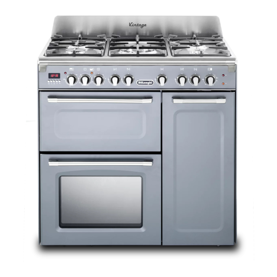
- Page 1 Users Operating Instructions Before operating this cooker, please read these instructions carefully DSC 90 DF Dual Fuel Cooker...
- Page 2 Introduction Congratulations on your purchase of this Delonghi Dual fuel cooker which has been carefully designed and produced to give you many years of satisfactory use. Before using this appliance it is essential that the following instructions are carefully read and fully understood.
- Page 3 IMPORTANT INSTRUCTIONS AND ADVICE FOR THE USE OF ELECTRICAL APPLIANCES The use of any electrical appliance requires the compliance with some basic rules, namely: – do not touch the appliance with wet or damp hands (or feet) – do not use the appliance whilst in bare feet –...
- Page 4 IMPORTANT SAFEGUARDS AND RECOMMENDATIONS After having unpacked the appliance, check to ensure that it is not damaged. In case of doubt, do not use it and consult your supplier or a professionally qualified technician. Packing elements (i.e. plastic bags, polystyrene foam, nails, packing straps, etc.) should not be left around within easy reach of children, as these may cause serious injuries.
- Page 5 ■ The various components of the appliance are recyclable. Dispose of them in accordance with the regulations in force in your country. If the appliance is to be scrapped, remove the power cord. ■ Always use oven gloves when removing the shelves and food trays from the oven whilst hot.
-
Page 6: Cooking Hob
Cooking hob Fig. 1.1 COOKING HOB 1. Auxiliary burner (A) 1,00 kW 2. Semi-rapid burner (SR) 1,75 kW 3. Rapid burner (R) 3,00 kW 4. Triple-ring burner (TR) 3,50 kW Important Note: The electric ignition is incorporated in the knobs. -
Page 7: Control Panel
Control panel Fig. 2.1 CONTROL PANEL - Controls description 1. Minute counter 2. Oven switch knob 3. Oven thermostat knob 4. Front left burner control knob 5. Rear left burner control knob 6. Central burner control knob 7. Rear right burner control knob 8. -
Page 8: Minute Counter
Minute counter MINUTE COUNTER The minute counter is a timed acoustic warning device which can be set for a maximum of 60 minutes. The knob (Fig. 3.1) must be rotated clockwise as far as the 60 minute position and then set to the required time by rotating it anticlockwise. Fig. -
Page 9: How To Use The Hob Burners
How to use the hob burners HOB BURNERS Each hob burner is controlled by a sep- arate gas tap operated by a control knob (fig. 4.1) which has 3 positions marked on the control panel, these are: – Symbol : tap closed (burner off) –... -
Page 10: Choice Of The Burner
CHOICE OF THE BURNER On the control panel, near each knob, there is a diagram that indicates which burner is controlled by that knob. Select the burner that is most suitable for the diameter and capacity of the pan to be used. -
Page 11: General Features
Fan oven OPERATING PRINCIPLES Attention: oven door becomes very hot during opera- Heating and cooking in the FAN oven tion. Keep children away. are obtained in the following ways: a. by forced convection A fan sucks in the air contained in the oven muffle, which sends it through GENERAL FEATURES the circular heating element and... -
Page 12: Oven Light
Fig. 5.2 Fig. 5.1 THERMOSTAT KNOB (Fig. 5.2) This only sets the cooking temperature and does not switch the oven on. Rotate clock- wise until the required temperature is reached (from 50 to 250°C). The light above the temperature selector will illuminate when the oven is swiched on and turns off when the oven reaches the correct temperature. -
Page 13: Hot Air Cooking
HOT AIR COOKING The circular element and fan come on. The heat is dispersed by forced convection and the temperature can be regulated to between 50° and 250°C via the thermostat knob. The oven does not require preheating. Recommended for: Food which has to be well-cooked outside and soft or rosy inside, for example lasagne, lamb, roast beef, whole fish etc. -
Page 14: Cooking Advice
COOKING ADVICE STERILIZATION Sterilization of foods to be conserved, in full and hermetically sealed jars, is done in the following way: a. Set the switch to position b. Set the thermostat knob to position 185 °C and preheat the oven. c. -
Page 15: Cooking Guide
Cooking guide Temperature and times given are approximate, as they will vary depending on the quality and amount of food being cooked. Remember to use ovenproof dishes and to adjust the oven temperature during cooking if necessary. APPROX. HEAT OF TYPE OF DISH TO COOK TEMPERATURE OVEN... -
Page 16: Important Notes
Important notes Installation, and any demonstration, information or adjustments are not included in the warranty. The cooker must be installed by a qualified person in accordance with the relevant Standards. In the UK C.O.R.G.I registered installers are authorised to undertake the installation and service work in compliance with the above regulations. -
Page 17: For Your Safety
Do’ s and do not’ s • Do always grill with oven door closed. • Do read the user instructions carefully before using the cooker for first time. • Do allow the oven to heat for one and a half hours, before using for the first time, in order to expel any smell from the new oven insulation, without the introduction of food. -
Page 18: Cleaning And Maintenance
Cleaning and maintenance GENERAL ADVICE – When the appliance is not being used, it is advisable to keep the gas tap closed. – Every now and then check to make sure that the flexible tube that connects the gas line or the gas cylinder to the appliance is in perfect condition and get it replaced if it shows any signs of wearing or damage. -
Page 19: Enamelled Parts
ENAMELLED PARTS All the enamelled parts must be cleaned with a sponge and soapy water or other non-abrasive products. Dry preferably with a microfibre or soft cloth. Acidic substances like lemon juice, tomato sauce, vinegar etc. can damage the enamel if left in contact for too long. - Page 20 BURNERS CORRECT REPLACEMENT OF THE BURNERS The burners can be removed and washed with soapy water only. It is very important to check that the They will remain perfect if always burner flame distributor F and the cap cleaned with products used for silver- C has been correctly positioned (see ware.
- Page 21 TRIPLE RING BURNER The triple ring burner must be correctly positioned (see fig. 7.3); the burner rib must be enter in their logement as shown by the arrow. The burners must be correctly positioned so that they cannot rotate (fig. 7.4). Then position the cap A and the ring B (fig.
-
Page 22: Storage Compartment
OVEN DOOR STORAGE COMPARTMENT The storage compartment is accessible The internal glass panel can be easily through the pivoting panel (fig. 7.7). removed for cleaning by unscrewing the 4 retaining screws (Fig. 7.6). Do not use harsh abrasive cleaners or sharp metal scrapers to clean Do not store flammable material in the oven or in the storage the oven door glass since they can... - Page 23 INSIDE OF OVEN The oven should always be cleaned after use when it has cooled down. The cavity should be cleaned using a mild detergent solution and warm water. Suitable proprietary chemical cleaners may be used after first consulting with manufacturers recommendations and testing a small sample of the oven cavity.
-
Page 24: Oven Floor
OVEN TRAY The oven tray must be correctly placed on the wire support (fig. 7.10) then inserted into the side runners (fig. 7.11). OVEN FLOOR The oven floor “F” (fig. 7.11) can be easily removed to facilitate cleaning. Remember to replace the floor correctly afterwards. Be careful not to confuse the tray “L”... -
Page 25: Removing The Oven Door
REMOVING THE OVEN Fig. 7.12A DOOR The oven door can easily be removed as follows: – Open the door to the full extent (fig. 7.12A). – Attach the retaining rings to the hooks on the left and right hinges (fig. 7.12B). -
Page 26: Advice For The Installer
Advice for the installer IMPORTANT – Cooker installation must only be carried out by QUALIFIED TECHNICIANS and in compliance with local safety standards. Failure to observe this rule will invalidate the warranty. – The appliance must be installed in compliance with regulations in force in your coun- try and in observation of the manufacturer's instructions. -
Page 27: Installation
Installation This cooker has class “2/1” overheating protection so that it can be installed next to a cabinet. The appliance may be installed in a kitchen, Kitchen/diner or a bed sitting room, but not in a room or space containing a bath or a shower. The appliance must not be installed in a bed-sitting room of less than 20 m The appliance is designed and approved for domestic use only and should not be installed in a commercial, semi commercial or communal environment. -
Page 28: Fitting The Adjustable Feet
FITTING THE ADJUSTABLE FEET The adjustable feet must be fitted to the base of the cooker before use. Rest the rear of the cooker on a piece of the polystyrene packaging exposing the base for the fitting of the feet. Fit the 4 legs by screwing them tight into the support base as Fig. -
Page 29: Moving The Cooker
MOVING THE COOKER WARNING When raising cooker to upright position always ensure two people carry out this manoeuvre to pre- vent damage to the adjustable feet (fig. 8.5). WARNING Be careful: do not lift the cooker by the door handle when raising to the upright position (fig. -
Page 30: Stability Bracket
Stability bracket We recommend a stability bracket is fitted to the cooker. The type shown in fig. 8.8 can be purchased from most plumbers merchants and do it yourself (D.I.Y.) shops. Existing slot in rear of cooker Bracket Fig. 8.8 Dotted line showing the position of cooker when fixed Outline of cooker... -
Page 31: Provision For Ventilation
PROVISION FOR VENTILATION ✓ The appliance should be installed into a room or space with an air supply in accor- dance with BS 5440-2: 2000. ✓ For rooms with a volume of less than 5 m - permanent ventilation of 100 cm free area will be required. -
Page 32: Gas Installation
Gas installation IMPORTANT NOTE This appliance is supplied for use on NATURAL GAS or LPG (check the gas regulation label attached on the appliance). ✓ Appliances supplied for use on NATURAL GAS: they are adjusted for this gas only and cannot be used on any other gas (LPG) without modification. The appliances are manufactured for conversion to LPG. -
Page 33: Gas Connection
Gas connection The installation of the gas appliance to Natural Gas or LP Gas must be carried out by a C.O.R.G.I. registered installer. Installers shall take due account of the provisions of the relevant British Standards Code of Practice, the Gas Safety Regulations and the Building Standards (Scotland)(Consolidation) Regulations issued by the Scottish Development Department. - Page 34 Cat: II 2H3+ Gas connection The gas supply must use the nearest gas inlet pipe which is located at the left or the right hand side at the rear of the appliance (figs. 9.1, 9.3). The hose should also be connected in such away that it does not touch the floor. To screw the connecting tube operate with two spanners (fig.
- Page 35 IMPORTANT PRESCRIPTIONS FOR GAS CONNECTION Rea r wall Suggested ar ea for gas mains connec tion Fig. 9.3...
-
Page 36: Adjusting Of The Minimum Of The Top Burners
Conversion to Natural Gas or to LPG INJECTORS REPLACEMENT OF THE TOP BURNERS If the injectors are not supplied they can be obtained from the “Service Centre”. The diameter is marked on the injector in cents of millimetre. Select the injectors to be replaced according to the “Table for the choice of the injectors”... -
Page 37: Lubrication Of The Gas Taps
TABLE FOR THE CHOICE OF THE INJECTORS Cat: 2H3+ G30 - 28-30 mbar Nominal Reduced BURNERS 20 mbar G31 - 37 mbar Power Power By-pass By-pass Ø injector Ø injector [kW] [kW] [1/100 mm] [1/100 mm] [1/100 mm] [1/100 mm] Auxiliary (A) 1,00 0,30... -
Page 38: Electrical Section
Electrical section The appliance must be connected to the electrical network verifying above all that the voltage corresponds to the value indicated on the specifications plate and that the cables section of the electrical plant can bear the load which is also indicated on the plate. - Page 39 Descriptions and illustrations in this booklet are given as simply indicative. The manufacturer reserves the right, considering the characteristics of the models described here, at any time and without notice, to make eventual necessary modifications for their construction or for commercial needs.
- Page 40 cod. 1103173 ß3...