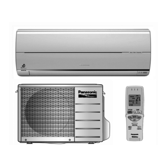
Panasonic CS-XE9EKE Service Manual
Hide thumbs
Also See for CS-XE9EKE:
- Brochure & specs (20 pages) ,
- Operating instructions manual (20 pages)
Table of Contents
Advertisement
TABLE OF CONTENTS
1 Safety Precautions----------------------------------------------- 3
2 Specifications ----------------------------------------------------- 5
2.1. CS-XE9EKE CU-XE9EKE------------------------------- 5
2.2. CS-XE12EKE CU-XE12EKE --------------------------- 7
3 Features ------------------------------------------------------------- 9
4 Location of Controls and Components ------------------10
4.1. Indoor Unit--------------------------------------------------10
4.2. Outdoor Unit -----------------------------------------------10
4.3. Remote Control -------------------------------------------10
5 Dimensions--------------------------------------------------------11
5.1. Indoor Unit & Remote Control ------------------------- 11
5.2. Outdoor Unit -----------------------------------------------12
6 Refrigeration Cycle Diagram --------------------------------13
7 Block Diagram----------------------------------------------------14
8 Wiring Connection Diagram ---------------------------------15
8.1. Indoor Unit--------------------------------------------------15
8.2. Outdoor Unit -----------------------------------------------16
9 Printed Circuit Board-------------------------------------------17
9.1. Indoor Unit--------------------------------------------------17
CS-XE9EKE CU-XE9EKE
CS-XE12EKE CU-XE12EKE
PAGE
9.2. Indicator ---------------------------------------------------- 19
9.3. Diagnosis--------------------------------------------------- 20
9.4. Outdoor Unit----------------------------------------------- 21
10 Installation Instruction ---------------------------------------- 23
10.1. Select The Best Location ------------------------------ 23
10.2. Indoor Unit ------------------------------------------------- 24
10.3. Outdoor Unit----------------------------------------------- 28
11 Operation and Function -------------------------------------- 31
11.1. Basic Function -------------------------------------------- 31
11.2. Airflow Direction ------------------------------------------ 31
of Dry Mode) ---------------------------------------------- 32
11.4. Powerful Mode Operation------------------------------ 33
11.5. ON Timer Control ---------------------------------------- 34
11.6. OFF Timer Control --------------------------------------- 34
11.7. Auto Restart Control------------------------------------- 34
11.8. Remote Control Signal Receiving Sound ---------- 34
11.9. Filter Cleaning Control ---------------------------------- 35
11.10. Ventilation Control --------------------------------------- 36
1
Order No. MAC0512111C8
Air Conditioner
PAGE
Advertisement
Table of Contents

Related Manuals for Panasonic CS-XE9EKE


Summary of Contents for Panasonic CS-XE9EKE
-
Page 1: Table Of Contents
PAGE 1 Safety Precautions----------------------------------------------- 3 9.2. Indicator ---------------------------------------------------- 19 2 Specifications ----------------------------------------------------- 5 9.3. Diagnosis--------------------------------------------------- 20 2.1. CS-XE9EKE CU-XE9EKE------------------------------- 5 9.4. Outdoor Unit----------------------------------------------- 21 2.2. CS-XE12EKE CU-XE12EKE --------------------------- 7 10 Installation Instruction ---------------------------------------- 23 3 Features ------------------------------------------------------------- 9 10.1. Select The Best Location ------------------------------ 23 4 Location of Controls and Components ------------------10 10.2. - Page 2 16.4. Gear Removal Instructions ---------------------------- 56 16.5. Outdoor Propeller Fan and Fan Motor -------------- 57 17 Technical Data---------------------------------------------------- 59 17.1. CS-XE9EKE CU-XE9EKE ----------------------------- 59 17.2. CS-XE12EKE CU-XE12EKE -------------------------- 67 17.3. Sensible Capacity Chart-------------------------------- 75 18 Exploded View and Replacement Parts List ----------- 76 18.1.
-
Page 3: Safety Precautions
1 Safety Precautions • Read the following “SAFETY PRECAUTIONS” carefully before perform any servicing. • Electrical work must be installed or serviced by a licensed electrician. Be sure to use the correct rating of the power plug and main circuit for the model installed. •... - Page 4 ATTENTION 1. Selection of the installation location. Select an installation location which is rigid and strong enough to support or hold the unit, and select a location for easy maintenance. 2. Power supply connection to the conditioner. Connect the power supply cord of the air conditioner to the mains using one of the following methods.
-
Page 5: Specifications
2 Specifications 2.1. CS-XE9EKE CU-XE9EKE Unit CS-XE9EKE CU-XE9EKE Performance Test Condition EUROVENT/AS Power Source (Phase, Voltage, Cycle) ø, V, Hz Single, 230 - 240, 50 Cooling Capacity 2.60 (0.60 - 3.00) kcal/h 2,240 (520 - 2,580) Heating Capacity 3.60 (0.60 - 6.10) - Page 6 Unit CS-XE9EKE CU-XE9EKE Air Circulation Description Cross-flow Fan Propeller Fan Material ASG20K1 Motor Type Transistor (8-poles) Induction (8-poles) Input 44.3 61.3 Rated Output Fan Speed Low (Cool/Heat) 800 / 850 — Medium (Cool/Heat) 980 / 1,050 — High (Cool/Heat) 1,170 / 1,280...
-
Page 7: Cs-Xe12Eke Cu-Xe12Eke
2.2. CS-XE12EKE CU-XE12EKE Unit CS-XE12EKE CU-XE12EKE Performance Test Condition EUROVENT/AS Power Source (Phase, Voltage, Cycle) ø, V, Hz Single, 230 - 240, 50 Cooling Capacity 3.50 (0.60 - 4.00) kcal/h 3,010 (520 - 3,440) Heating Capacity 4.80 (0.60 - 6.70) kcal/h 4,130 (520 - 5,760) Moisture Removal... - Page 8 Unit CS-XE12EKE CU-XE12EKE Heat Exchanger Description Evaporator Condenser Tube material Copper Copper Fin material Aluminium (Pre Coat) Aluminium Fin Type Slit Fin Corrugated Fin Row / Stage (Plate fin configuration, forced draft) 2 / 15 2 / 24 Size (W 25.4 718.4 36.4...
-
Page 9: Features
3 Features • High Efficiency • Compact Design • Wider range of horizontal discharge air • Long Installation Piping - up to 15 meter for XE9EK & XE12EK • SUPER alleru buster - Inactivate various harmful airborne elements including allergens, viruses and bacteria •... -
Page 10: Location Of Controls And Components
4 Location of Controls and Components Note: 4.3. Remote Control * Movable front panel will open slightly for air intake purposes once the air conditioner operation starts. Movable front panel will remain open during air conditioner operation. It will close automatically once the air conditioner operation stops. -
Page 11: Dimensions
5 Dimensions 5.1. Indoor Unit & Remote Control... -
Page 12: Outdoor Unit
5.2. Outdoor Unit... -
Page 13: Refrigeration Cycle Diagram
6 Refrigeration Cycle Diagram... -
Page 14: Block Diagram
7 Block Diagram... -
Page 15: Wiring Connection Diagram
8 Wiring Connection Diagram 8.1. Indoor Unit... -
Page 16: Outdoor Unit
8.2. Outdoor Unit... -
Page 17: Printed Circuit Board
9 Printed Circuit Board 9.1. Indoor Unit TOP VIEW... - Page 18 BOTTOM VIEW...
-
Page 19: Indicator
9.2. Indicator TOP VIEW BOTTOM VIEW... -
Page 20: Diagnosis
9.3. Diagnosis TOP VIEW BOTTOM VIEW... -
Page 21: Outdoor Unit
9.4. Outdoor Unit TOP VIEW... - Page 22 BOTTOM VIEW...
-
Page 23: Installation Instruction
10 Installation Instruction 10.1. Select The Best Location Indoor Unit Indoor/Outdoor Unit Installation Diagram • There should not be any heat source or steam near the unit. • There should not be any obstacles blocking the air circula- tion. • A place where air circulation in the room is good. •... -
Page 24: Indoor Unit
10.2. Indoor Unit 2. Drill the piping plate hole with ø70 mm hole-core drill. • Line according to the left and right side edge of the instal- 10.2.1. How To Fix Installation Plate lation plate. The meeting point of the extended line is the centre of the hole. -
Page 25: Indoor Unit Installation
When using the extension ventilation hose (optional) 10.2.4. Indoor Unit Installation For the right rear piping For the right and right bottom piping 1. Removing the bottom left corner 2. Connecting and fixing the ventilation hose to the ventila- tion hole of the unit 3. - Page 26 For the embedded piping 2. Install the Indoor Unit 3. Secure the Indoor Unit 4. Insert the connecting cable 1. Pull out the piping and drain hose...
- Page 27 5. Treating methods of the end of the ventilation hose (This can be used for left rear piping & left bottom piping also.)
-
Page 28: Outdoor Unit
10.2.5. Connect The Cable To The Indoor 10.3.2. Connecting The Piping Unit Connecting The Piping To Indoor Unit Please make flare after inserting flare nut (locate at joint portion 1. The inside and outside connecting cable can be con- of tube assembly) onto the copper pipe. nected without removing the front grille. - Page 29 10.3.3. Evacuation Of The Equipment (For Europe & Oceania Destination) WHEN INSTALLING AN AIR CONDITIONER, BE SURE TO EVACUATE THE AIR INSIDE THE INDOOR UNIT AND PIPES in the following procedure. 1. Connect a charging hose with a push pin to the Low and High side of a charging set and the service port of the 3-way valve. •...
-
Page 30: Connect The Cable To The Outdoor Unit
10.3.4. Connect The Cable To The Outdoor Unit 1. Remove the control board cover from the unit by loosening the screw. 2. Connecting cable between indoor unit and outdoor unit shall be approved polychloroprene sheathed 5 x 1.5 mm flexible cord, type designation 245 IEC 57 or heavier cord. -
Page 31: Operation And Function
11 Operation and Function 11.1. Basic Function Inverter control, which equipped with a microcomputer in determining the most suitable operating mode as time passes, auto- matically adjusts output power for maximum comfort always. In order to achieve the suitable operating mode, the microcom- puter maintains the set temperature by measuring the temperature of the environment and performing temperature shifting. -
Page 32: Quiet Operation (Cooling Mode/Cooling Area Of Dry Mode)
11.2.2. Horizontal Airflow 1. Automatic horizontal airflow direction can be set using remote control; the vane swings left and right within the angles as stated below. For heating mode operation, the angle of the vane depends on the indoor heat exchanger temperature as Fig- ure 1 below. -
Page 33: Powerful Mode Operation
2. When quiet operation is stopped, operation is shifted to normal operation with previous setting. 3. When fan speed is changed, quiet operation is shifted to quiet operation of the new fan speed. 4. When operation mode is changed, quiet operation is shifted to quiet operation of the new mode. 5. -
Page 34: On Timer Control
(b) Soft Dry Operation (c) Heating Operation 11.5. ON Timer Control ON timer can be set using remote control, the unit with timer set will start operate earlier than the setting time. This is to provide a comfortable environment when reaching the set ON time. 60 minutes before the set time, indoor (at fan speed of Lo-) and outdoor fan motor start operate for 30 seconds to determine the indoor intake air temperature and outdoor air temperature in order to judge the operation starting time. -
Page 35: Filter Cleaning Control
11.9. Filter Cleaning Control • Filter cleaning function helps to: - Clean the filters automatically on a regular basis. - Avoid airflow blockage caused by dusty filter. - Prevent growth of mold inside the unit. - Improve cooling effect that saves energy consumption. •... -
Page 36: Ventilation Control
11.10. Ventilation Control • To circulate the indoor air. • The ventilation operation is enable by pressing the VENTILATION Button. (As a default setting, ventilation will be turned on auto- matically once the air conditioner operation starts). 11.10.1. Simultaneous Operation •... -
Page 37: Protection Control
(But, up to programmed frequency.) 2. If total running current exceeds l2, compressor is stopped immediately. 3. If it happens three (3) times within 20 minutes, operation will be stopped and Timer LED blinks. (“F98” is activating.) Running current CS-XE9EKE CS-XE12EKE Cooling 3.7A 5.8A... -
Page 38: Four-Way Valve Operation Detection Control (Switching Abnormality Between Cooling And Heating)
12.8. Four-way Valve Operation Detection Control (Switching Abnormality between Cool- ing and Heating) In Cooling operation 1. When indoor heat exchanger temperature exceeds 45 C in 4 minutes after compressor starts, compressor will be stopped. 2. If the above excess occurs 4 times per 30 minutes, timer LED is to be blinking. (“F11” is to be confirmed.) In Heating operation 1. -
Page 39: Servicing Mode
13 Servicing Mode 13.1. Auto OFF/ON Button This button is used to pump down the air conditioner during servicing or transferring of outdoor unit. 1. It can be used to operate the air conditioner in limited function if remote control is misplaced or malfunction. •... -
Page 40: Various Setting Mode
13.2. Various Setting Mode 13.2.1. Remote Control Number Switch Mode • Set remote control number through receiving signal from remote control. (Please refer to Select Remote Control Transmission Code). 13.2.2. Current Setting • Choose the Current Setting by pressing AUTO OFF/ON button. 13.2.3. -
Page 41: Individual Correspondence Mode
13.2.4. Filter Cleaning Operation Setting Choose the operation setting by pressing AUTO OFF/ON button. Setting Operation • Filter cleaning will run automatically after the air conditioner operation stops (air conditioner is turned off using remote control). • After the filter cleaning is completed, the air conditioner operation will remain off. •... -
Page 42: Select Remote Control Transmission Code
• During Receiving Sound ON/OFF setting mode, press AUTO OFF/ON Button to toggle the Receiving sound. • During H14 Abnormal Detection Selection Mode, press AUTO OFF/ON Button to toggle the Abnormal detection. • During Ventilation Quiet mode, press AUTO OFF/ON Button to toggle the Ventilation setting. •... -
Page 43: Demo Mode
14 Demo Mode • The purpose of Demo Mode is to demonstrate the filter cleaning function. • The Demo Mode can be activated by using AUTO OFF/ON button. • The Demo Mode is activated by AUTO OFF/ON button. (Beep • The Demo Mode activation does not start the demonstration. •... -
Page 44: Troubleshooting Guide
15 Troubleshooting Guide 15.1. Refrigeration Cycle System In order to diagnose malfunctions, make sure that there are no electrical problems before inspecting the refrigeration cycle. Such problems include insufficient insulation, problem with the power source, malfunction of a compressor and a fan. The normal outlet air temperature and pressure of the refrigera- tion cycle depends on various conditions, the standard values for them are shown in the table to the right. -
Page 45: Relationship Between The Condition Of The Air Conditioner And Pressure And Electric Current
15.2. Relationship Between The Condition of The Air Conditioner and Pres- sure and Electric Current Cooling Mode Heating Mode Condition of the air conditioner Low Pressure High Pressure Electric current Low Pressure High Pressure Electric current during operation during operation Insufficient refrigerant (gas leakage) Clogged capillary tube or... -
Page 46: Breakdown Self Diagnosis Function
15.3. Breakdown Self Diagnosis Function 15.3.1. Self Diagnosis Function (Three Digits Alphanumeric Code) • Once abnormality has occurred during operation, the unit pressing the CHECK button continuously for 5 seconds or will stop its operation, and Timer. operating the unit for 30 seconds. •... -
Page 47: Error Codes Table
15.4. Error Codes Table Diagnosis Abnormality / Protection control Abnormality Emergency operation Primary location to verify display Judgement No abnormality detected — Normal operation — Indoor / Outdoor abnormal communica- > 1 min after starting Indoor fan operation • Internal / external cable connections tion operation only... -
Page 48: Movable Front Panel Malfunction
15.5. Movable Front Panel Malfunction • Movable front panel does not opens/fully opens during air conditioner operation. • This happen when the front panel has been interrupted during operations. • Follow below instructions to reset the air conditioner memory. 1. Press OFF/ON button to stop the air conditioner operation. 2. -
Page 49: Disassembly And Assembly Instructions
16 Disassembly and Assembly Instructions 16.1. Indoor Electronic Controller, Auto Cleaning, Cross Flow Fan and Fan Motor Removal Procedures 1. Open and release the Intake Grille complete (Front). (Fig. 1) Fig. 1 2. Remove the Intake Grille Complete (Top). (Fig. 2) 3. - Page 50 10. Releasing the CN-FM, CN-FB, CN-CLNSW, CN-TH, CN-SIDESW, CN-VENT & CN-AUTO. (Fig. 5) 11. Releasing the 2 Terminals (Brown and Black) Fig. 5 12. Releasing the AC02 terminal. Fig. 6 13. Slide out the Indoor Electronic Controller. (Fig. 7) Fig. 7...
- Page 51 14. Remove the Auto Cleaning Complete by releasing the 5 screws. (Fig. 8). For detailed instructions, please refer to 16.2 Filter Cleaning Device Complete Removal Instructions. Fig. 8 15. Remove the Control Board by releasing the screw. (Fig. 9) Fig. 9 16.
- Page 52 19. Remove the screw at the Cross Flow fan. (Fig. 12) Reminders:- To reinstall the Fan Motor, please adjust the connector location is posi- tioned 45 with Fan Motor before fixing Control Board Cover. (Fig. 12) Fig. 12 20. Remove the Bearing. (Fig. 13) 21.
-
Page 53: Filter Cleaning Device Complete Removal Instructions
16.2. Filter Cleaning Device Complete Removal Instructions Tools Required: • Screw driver (+ type) Switch off the power supply and unplug before cleaning or servicing. • Cutter 1. Remove the front intake grille. 2. Push to remove top intake grille. 3. - Page 54 8. Remove all connectors from the PCB. 9. Remove screws (5 pieces). 10. Lift the filter cleaning device gently to remove.
-
Page 55: Ventilation Device Removal Instructions
16.3. Ventilation Device Removal Instructions 1. Cut the cable tie and remove the flexible hose connector. 2. Unscrew (1 piece). 3. Disconnect the connector. 4. Unscrew (2 pieces). 5. Disconnect the ventilation device from the duct. 6. Remove the ventilation device. -
Page 56: Gear Removal Instructions
16.4. Gear Removal Instructions 1. Unscrew (3 pieces). 2. Remove the gear. 3. Disconnect the connector from the gear. -
Page 57: Outdoor Propeller Fan And Fan Motor
16.5. Outdoor Propeller Fan and Fan Motor... -
Page 59: Technical Data
17 Technical Data 17.1. CS-XE9EKE CU-XE9EKE A. Cool: Outdoor Temperature Change Indoor Temp.: 27/19 C Remote Con.: HI FAN, COOL 16 C Comp. Hz: Rated Cooling Voltage: 230 V... - Page 61 B. Cool: Pipe Length Change Indoor Temp.: 27/19 C, 35/- C Remote Con.: HI FAN, COOL 16 C Comp. Hz: Rated Cooling Voltage: 230 V...
- Page 63 C. Heat: Outdoor Temperature Change Indoor Temp.: 20/- C Remote Con.: HI FAN, HEAT 30 C Comp. Hz: Rated Heating Voltage: 230 V...
- Page 65 D. Heat: Pipe Length Change Indoor Temp.: 20/- C, 7/6 C Remote Con.: HI FAN, HEAT 30 C Comp. Hz: Rated Heating Voltage: 230 V...
-
Page 67: Cs-Xe12Eke Cu-Xe12Eke
17.2. CS-XE12EKE CU-XE12EKE A. Cool: Outdoor Temperature Change Indoor Temp.: 27/19 C Remote Con.: HI FAN, COOL 16 C Comp. Hz: Rated Cooling Voltage: 230 V... - Page 69 B. Cool: Pipe Length Change Indoor Temp.: 27/19 C, 35/- C Remote Con.: HI FAN, COOL 16 C Comp. Hz: Rated Cooling Voltage: 230 V...
- Page 71 C. Heat: Outdoor Temperature Change Indoor Temp.: 20/- C Remote Con.: HI FAN, HEAT 30 C Comp. Hz: Rated Heating Voltage: 230 V...
- Page 73 D. Heat: Pipe Length Change Indoor Temp.: 20/- C, 7/6 C Remote Con.: HI FAN, HEAT 30 C Comp. Hz: Rated Heating Voltage: 230 V...
-
Page 75: Sensible Capacity Chart
17.3. Sensible Capacity Chart Condition Indoor temperature : 27 C / 19 C Outdoor temperature : 35 C / 24 C CS-XE9EKE CU-XE9EKE 230V - 240V Outdoor Temperature ( C) Indoor wet bulb temperature 17.0 C 2.58 1.96 0.52 2.41 1.88... -
Page 76: Exploded View And Replacement Parts List
18 Exploded View and Replacement Parts List 18.1. Indoor Unit Note: The above exploded view is for the purpose of parts disassembly and replacement. The non-numbered parts are not kept as standard service parts. - Page 77 REF. NO. PART NAME & DESCRIPTION QTY. CS-XE9EKE CS-XE12EKE REMARKS CHASSY COMPLETE CWD50C1507 FAN MOTOR CWA981172J CROSS FLOW FAN COMPLETE CWH02C1045 BEARING ASS’Y CWH64K007 SCREW - CROSS FLOW FAN CWH551146 CASING FOR FAN MOTOR CWD911567 DUCT - COMPLETE CWD22C1037 RETAINING RING...
-
Page 78: Outdoor Unit
18.2. Outdoor Unit Note: The above exploded view is for the purpose of parts disassembly and replacement. The non-numbered parts are not kept as standard service parts. - Page 79 REF. NO. PART NAME & DESCRIPTION QTY. CU-XE9EKE CU-XE12EKE REMARKS CHASSY ASS’Y CWD50K2117 ANTI - VIBRATION BUSHING CWH50077 COMPRESSOR, DC 220V 5CS110XBD04 NUT - COMPRESSOR MOUNT CWH56000J CRANKCASE HEATER CWA341026 SOUND PROOF MATERIAL CWMG300001 FAN MOTOR BRACKET CWD541021 FAN MOTOR, DC 40W 3PH ARW44W8P40AC SCREW - BRACKET FAN MOTOR CWH551060J...