Table of Contents
Advertisement
Quick Links
Advertisement
Chapters
Table of Contents

Related Manuals for Bosch AMC-4W


Summary of Contents for Bosch AMC-4W
- Page 1 Access Controller AMC-4W Bosch Security Systems | V.3.1/2006-09...
- Page 2 Trademarks Access Controller AMC-4W Trademarks Bosch is a registered trademark of Bosch Security Systems in the United States and/or other countries. Remarks This hardware is part of a security system. Access shall be limited to authorized persons only. Some states do not allow the exclusion or limitation of implied warranties, or limitation of liability for incidental or consequential damages, so the above limitation or exclusion might not apply to you.
-
Page 3: Table Of Contents
Installing the AMC-4W..............21 5.1. Mounting the AMC-4W ..............21 5.1.1. Mounting on rails ................21 5.1.2. Demounting the AMC-4W from mounting rails ........ 21 5.2. Opening the AMC-4W Case............... 22 5.3. Cabling ....................22 5.4. Grounding and Shielding..............23 5.5. - Page 4 Access Controller AMC-4W 5.12. Connecting Analog Input Devices............38 5.13. Tamper Protection ................40 Operating the AMC-4W ..............41 6.1. Status Display of the AMC-4W............41 6.2. Configuring the Ethernet Interface ............. 42 6.3. Resetting the AMC-4W..............42 Appendix ................... 44 7.1.
-
Page 5: Please Read The Following Notes Carefully
Bosch Security Systems Tel.: +49 24 05 / 60 05-0 Adenauerstr 20 / A3 Fax: +49 24 05 / 60 05-29 D-52146 Würselen Email: info.service@de.bosch.com Germany Bosch Security Systems | V.3.1/2006-09 Installation Guide... -
Page 6: Safety Instructions
• If the unit has been dropped or the cabinet damaged. • If the unit exhibits a distinct change in performance, this indicates that service is needed. Installation Guide Bosch Security Systems | V.3.1/2006-09... - Page 7 3−wire grounding plug (a plug with a third pin, for grounding). This safety feature allows the plug to fit into a grounding power outlet only. If unable to insert the plug into the outlet, contact an electrician to arrange Bosch Security Systems | V.3.1/2006-09 Installation Guide...
-
Page 8: Fcc & Ices Information
The user may find the following booklet, prepared by the Federal Communications Commission, helpful: How to Identify and Resolve Radio-TV Interference Problems. This booklet is available from the U.S. Government Printing Office, Washington, DC 20402, Stock No. 004-000-00345-4. Installation Guide Bosch Security Systems | V.3.1/2006-09... -
Page 9: Safety Precautions
Health and Safety Installation of the AMC-4W must comply with any local fire, health and safety regulations. A secured door that may be part of an escape route from an area must be installed with: •... -
Page 10: Unpacking
Security Systems salesperson. The shipping carton is the safest transport container for the unit. Store it and the other packaging material for future use. If the unit has to be sent back, use the original packaging. Installation Guide Bosch Security Systems | V.3.1/2006-09... -
Page 11: Description Of The Amc-4W
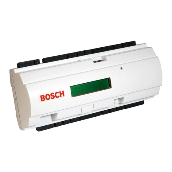
Description of the AMC-4W 3. Description of the AMC-4W The AMC-4W is equipped with four independent interfaces for Wiegand type readers. By that it is able to control two doors with a reader in each direction and up to four doors with a reader in one direction only. -
Page 12: Figure 2: The Amc-4W In A Four Door Safety Lock
The AMC-4W electronic is completely covered by a plastic housing. The LC Display provides all important status information. The setup procedure for an AMC-4W is very simple and extremely fast by the use of door templates. Once selected, all the inputs and outputs are predefined. -
Page 13: Equipment Configuration
Access Controller AMC-4W Description of the AMC-4W 3.1. Equipment Configuration Figure 3: Upper circuit board with display (top side) 1. Internal tamper contact 2. Fuseholder, not used in this application 3. Jumper: interface selector RS485 Host connection, RS485 two wire or RS485 four wire (depends on external wiring) 4. - Page 14 Description of the AMC-4W Access Controller AMC-4W 10. Compact Flash (optional size) 11. LC Display 12. Configurable 10/100 Mbit/s Ethernet interface Installation Guide Bosch Security Systems | V.3.1/2006-09...
-
Page 15: Figure 4: Lower Circuit Board (Bottom Side)
Description of the AMC-4W Figure 4: Lower circuit board (bottom side) 13. Jumper: Selector for either potential free relay output or powered by AMC-4W internal power supply (wet/dry contacts) 14. Jumper: Potential equalization between different mass systems and protective earth (shield) 15. -
Page 16: Performance Characteristics
Description of the AMC-4W Access Controller AMC-4W Figure 5: Lower circuit board connections (bottom side) 3.2. Performance Characteristics Host address selectable via DIL sliding switch Four possible configurable host interfaces: RS485 2-wire RS485 4-wire RS232 Ethernet 10/100 Mbit/s Four peripheral input devices via Wiegand interface... -
Page 17: System Overview
By default a management host system is connected via Ethernet. A management host connection via RS485 or RS232 is also possible. In RS485 mode up to eight access controllers AMC-4W can be combined on one party line. Via Wiegand interfaces up to four peripheral devices can be connected to each AMC-4W. -
Page 18: Technical Data
64,8 mm x 13,9 mm 1 line, 16 characters Power consumption Internal: 3,1 VA Peripheral devices Deutronic: Up to 56VA at 12V DC Altronix: Up to 66 VA at 12V DC Connectors Pluggable screw connectors Installation Guide Bosch Security Systems | V.3.1/2006-09... - Page 19 For short distances below 25m (75 feet) use AWG18 connection to power conductors. For higher distances install an additional supply power supply close to the AMC-4W. Please, calculate the voltage drop by checking the conductor specifications for characteristic resistance values. The voltage drop shall not exceed 2V.
- Page 20 RS485 slave Please, calculate your voltage drop (see above) by checking conductor specifications for characteristic resistance values. Note: The voltage drop at the different cables add up! Their sum shall be less than 2V! Installation Guide Bosch Security Systems | V.3.1/2006-09...
-
Page 21: Installing The Amc-4W
5.1.1. Mounting on rails The AMC-4W can be attached on a standard 35 mm mounting rail via a snap-in mechanism. Attach the AMC-4W into the lower edge of the mounting rail, the lift the AMC-4W and snap it onto the rail by pushing it towards the back. -
Page 22: Opening The Amc-4W Case
The AMC-4W case consists of a top cover mounted with a three-point snap-in closure on a ground chassis. To open the AMC-4W case push the left side of the top cover (single catch) and pull the top cover from the chassis. -
Page 23: Grounding And Shielding
The AMC-4W enables you to set up a central ground or shielding point, simply by setting a couple of jumpers. Set these jumpers only if ground or shield is not connected otherwise. -
Page 24: Figure 11: Location Of Ground Jumpers Bottom Side Circuit Board
Setting jumper 3 connects the internal ground of the AMC-4W to the shield of the RS485 host interface. Set Jumper 3 only at the first AMC-4W of a party line. The host system must not connect cable shield and protective ground. If the AMC-4W is set to RS232 mode, Jumper 3 must be set. -
Page 25: Connecting Power Supply
6 (positive) and pin 7 (negative). Caution! Risk of Damage! Power supply for external devices is 12 VDC only! Applying higher voltages may cause hazards to people and damage to the equipment.. Bosch Security Systems | V.3.1/2006-09 Installation Guide... - Page 26 If an uninterruptible power supply (UPS) is used, the relay output for power good signals from the UPS is connected to pin 4 and pin 5. Otherwise these two pins must be short-circuited. Installation Guide Bosch Security Systems | V.3.1/2006-09...
-
Page 27: Rs485 Host Interface
Bus devices are the AMC-4W. Peripheral devices are card readers, door control units, locks, signals, alarm devices, etc. which are connected to the AMC-4W. Maximum cable length of a bus line must not exceed 1200m or 4000ft. The cable length of branch lines must not exceed 100m or 300ft. -
Page 28: Rs485 Two Wire Connection
Both connectors of the RS485 interface of the AMC-4W can be bus lines. For longer bus lines connect the AMC-4W to multiple AMC-MUX-EXT. To use RS485 mode at the AMC-4W, connect the data cables to the pluggable screw connector of the RS485 host interface. Then set the RS485 address via DIL switch or software and activate the RS485 two-wire or four-wire mode via jumper settings. -
Page 29: Rs485 Four Wire Connection
A complete connection diagram of the RS485 host interface is shown in chapter 7.1 ‘Connecting Diagrams’ of this documentation. 5.6.2. RS485 Four Wire Connection Figure 17: Connection scheme of an RS485 four wire connection Bosch Security Systems | V.3.1/2006-09 Installation Guide... -
Page 30: Dil Switch Address Selector
DIL Switch Address Selector The first four DIL switches for address selection define the RS485 address of the AMC-4W in a RS485 bus system. Switch 5 selects on of the two different protocols, SDEB and BPA (according to DIN6619). Switch 6 sets the connection to the host system to either RS232 or RS485. - Page 31 Access Controller AMC-4W Installing the AMC-4W Address DIL Switches None Mode DIL Switches SDEB RS232 RS485 Bosch Security Systems | V.3.1/2006-09 Installation Guide...
-
Page 32: Rs232 Host Interface
Installing the AMC-4W Access Controller AMC-4W 5.7. RS232 Host Interface The AMC-4W offers an RS232 serial interface to connect a host computer or serial modem. Cable length between two RS232 COM serial interfaces must not exceed 15 meters (45 ft). -
Page 33: Ethernet Interface
The AMC-4W offers an additional 10/100 Mbit/s Ethernet auto-sensing interface to connect to a local area network or host computer. Use either a CAT5 crossover cable to connect the AMC-4W directly to a computer’s network interface or a standard CAT5 patch cable to connect the AMC-4W to a network hub or network switch. -
Page 34: Rs485 Extension Module Bus
Access Controller AMC-4W 5.9. RS485 Extension Module Bus The RS485 Extension Module Bus expands the AMC-4W with additional I/O modules. Up to three expansion modules can be connected to provide additional in- and outputs, for example, for elevator control. Figure 22: Location of the RS485 extension module bus A complete connection diagram of the RS485 extension module bus is shown in chapter 7.1 ‘Connecting Diagram’... -
Page 35: Wiegand Interface For Card Readers
Installing the AMC-4W 5.10. Wiegand Interface for Card Readers The AMC-4W has four Wiegand interfaces to integrate up to four card readers with Wiegand compatible interfaces. Each interface is connected via a 10-pin pluggable screw connector (S5, S9, S13 and S17). -
Page 36: Connecting Relay Outputs
Access Controller AMC-4W 5.11. Connecting Relay Outputs To operate locks or alarm systems the AMC-4W has eight form C relay outputs.. Each relay output can operate in ‘wet’ mode, using the AMC-4W's internal 12V DC power supply for external devices or ‘dry’ mode with potential free contacts for externally powered systems. -
Page 37: Figure 25: Location Of The Relay Output Connectors
7.1 ‘Connecting Diagram’ of this documentation. Each relay output has a separate jumper setting on the bottom side of the lower circuit board to activate wet or dry mode. Figure 26: Location of relay output jumpers (bottom side) Bosch Security Systems | V.3.1/2006-09 Installation Guide... -
Page 38: Connecting Analog Input Devices
The AMC-4W has eight analog inputs, for example, for potential free lock mechanisms or to detect if a lock is closed or open. The AMC-4W can also detect the wiring conditions ‘short circuit’ and ‘broken’ and initiate an alarm if the appropriate devices are connected. - Page 39 All input devices are connected by means of 4-pin pluggable screw connectors of the AMC-4W. A complete connection diagram for analog input devices is shown in chapter 7.1 ‘Connecting Diagram’ of this documentation. Bosch Security Systems | V.3.1/2006-09 Installation Guide...
-
Page 40: Tamper Protection
Figure 28: Location of the analog input connectors 5.13. Tamper Protection To protect the AMC-4W against unauthorized access and prevent the AMC-4W from tampering with sensitive data, the AMC-4W offers an additional interface to connect external tamper contacts. This interface is a potential-free 2-pin pluggable screw connector marked with T. -
Page 41: Operating The Amc-4W
6. Operating the AMC-4W 6.1. Status Display of the AMC-4W The LC Display delivers information about the AMC-4W status. Push the 'Dialog' button as shown in figure 30 to switch between different modes. Figure 30: Location of the ‘Dialog’ button The display mode which has been set remains until the next operation of the ‘Dialog’... -
Page 42: Configuring The Ethernet Interface
1. Insert the provided screwdriver into the hole as shown in figure 31 2. Push the reset button for at least three seconds. 3. The AMC-4W will be reset and reboots. You are back in the download program. 4. Now it is possible to reconfigure the AMC-4W from the beginning. -
Page 43: Figure 31: Restarting The Amc-4W With The Provided Screw Driver
3. Set all six DIL switches of the RS485 selector to ON 4. Press the tamper switch on the upper left side of the board 5. The AMC-4W will now have the following network configuration: DHCP = 0 b. IP = 127.0.0.1... -
Page 44: Appendix
Appendix Access Controller AMC-4W 7. Appendix 7.1. Connecting Diagrams Figure 33: Connector blocks of the AMC-4W Installation Guide Bosch Security Systems | V.3.1/2006-09... -
Page 45: Figure 34: Power Supply
Access Controller AMC-4W Appendix Figure 34: Power supply Figure 35: Relay outputs, analog inputs and Wiegand interface Bosch Security Systems | V.3.1/2006-09 Installation Guide... -
Page 46: Figure 36: Rs485 Slave Interface And Tamper Contact
Appendix Access Controller AMC-4W Figure 36: RS485 Slave Interface and Tamper Contact Figure 37: Connectors on upper PCB Figure 38: RS485 Host on upper PCB Installation Guide Bosch Security Systems | V.3.1/2006-09... -
Page 47: Figure 39: Ethernet Network Socket (Rj45)
Access Controller AMC-4W Appendix Figure 39: Ethernet Network socket (RJ45) Figure 40: Connecting diagram of the RS232 serial interface Bosch Security Systems | V.3.1/2006-09 Installation Guide... -
Page 48: Jumpers
Jumper Setting Selects RS485 two-wire-mode or four-wire-mode Connects internal ground to RS485 host interface ground Connects internal ground to RS485 host interface shield DIL switch for transfer mode and RS485 host interface address selection Installation Guide Bosch Security Systems | V.3.1/2006-09... -
Page 49: Figure 42: Jumper Settings Lower Circuit Boards
Relay output 7 – wet/dry mode selector Relay output 3 – wet/dry mode selector JP10 Relay output 4 – wet/dry mode selector JP11 Relay output 1 – wet/dry mode selector JP12 Relay output 2 – wet/dry mode selector Bosch Security Systems | V.3.1/2006-09 Installation Guide... -
Page 50: Legend
Appendix Access Controller AMC-4W 7.3. Legend Twisted pair connection Transmitter Receiver Installation Guide Bosch Security Systems | V.3.1/2006-09... -
Page 51: Product Declaration
Disturbance Sensors. 7.5.2. UL Listing UL 294 – Access Control System Units 7.5.3. Safety EN60950: 2000 The AMC-4W is in conformance with CE rules. 7.6. Included in delivery AMC-4W Screw driver Product documentation Bosch Security Systems | V.3.1/2006-09 Installation Guide... -
Page 52: List Of Figures
Figure 22: Location of the RS485 extension module bus ......... 34 Figure 23: Location of the Wiegand interfaces for external devices ....35 Figure 24: Wet mode and dry mode of the AMC-4W relay outputs....36 Figure 25: Location of the relay output connectors .......... 37 Figure 26: Location of relay output jumpers (bottom side) ...... - Page 53 Figure 29: Location of the tamper protection contact ........40 Figure 30: Location of the ‘Dialog’ button ............41 Figure 31: Restarting the AMC-4W with the provided screw driver....43 Figure 32: Resetting the AMC-4W to delivery state......... 43 Figure 33: Connector blocks of the AMC-4W..........44 Figure 34: Power supply ...................
-
Page 54: Index
Hardware ........17 System Overview....... 16 Housing material......18 Technical Data ......17 Humidity........18 UL Listing........50 Installing the AMC-4....20 Used Symbols ......5 Internet......... 5 Wiegand Interface...... 33 Legend ........49 Installation Guide Bosch Security Systems | V.3.1/2006-09...