
Related Manuals for Honeywell Excel 50


Summary of Contents for Honeywell Excel 50
- Page 1 Excel 50 CONTROLLER HONEYWELL EXCEL 5000 OPEN SYSTEM INSTALLATION INSTRUCTIONS Copyright © 2005 Honeywell Inc. • All Rights Reserved EN1B-0101GE51 R1105D 95-7568-10...
- Page 2 EXCEL 50 INSTALLATION INSTRUCTIONS Trademark Information Echelon, LON, L , LonBuilder, NodeBuilder, LonManager, ORKS LonTalk, LonUsers, LonPoint, Neuron, 3120, 3150, the Echelon logo, the L logo, and the LonUsers logo are trademarks of Echelon Corporation registered in the United States and other countries. LonLink, LonResponse, LonSupport, and LonMaker are trademarks of Echelon Corporation.
-
Page 3: Table Of Contents
EXCEL 50 INSTALLATION INSTRUCTIONS CONTENTS Revision Overview..................................5 General ......................................5 Safety Instructions ....................5 Hardware Overview ....................6 Version Overview...................... 6 Dimensions ....................... 7 Mounting ....................................... 8 Housing ........................8 Front Door ......................8 Inside Cabinet without MMI .................. 9 Inside Cabinet with MMI .................. - Page 4 EXCEL 50 INSTALLATION INSTRUCTIONS MMI Connection....................24 Cable Specifications....................24 Modem or ISDN Terminal Adapter Connections ..........24 Changing Between MMI and Modem Connection ..........24 Remote Communications ................................25 Modem Requirements .....................25 No Set-up for Standard Modem Behavior..............25 Automatic Baudrate Synchronization...............25 Auto / Manual Answer Detection ................25 Resetting the Modem ....................25...
-
Page 5: Revision Overview
Disconnect the power supply before you start to in- stall the Excel 50 Controller. Do not reconnect the • The Excel 50 Controller may be installed and mounted power supply until you have completed installation. only by authorized and trained personnel. -
Page 6: Hardware Overview
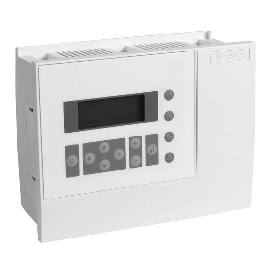
Short Slave Power RS232C RX TX Fig. 5. Meter-Bus adapter Fig. 1. Excel 50 Controller housing Fig. 6. Mounting accessories Fig. 2. Screw terminal blocks Version Overview *Version can be upgraded by firmware. Firmware with Housing: integrated modem communication is available for down- With Man-Machine-Interface (MMI) loading to the controller. -
Page 7: Dimensions
EXCEL 50 INSTALLATION INSTRUCTIONS Dimensions 7.79 in. (198 mm) LCD DISPLAY FAST ACCESS APPLICATION KEYS MODULE BASIC FUNCTION KEYS 2.76 in. (70 mm) C-BUS PORT 2.83 in. (72 mm) 3.19 in. (81 mm) STANDARD DIN-CUTOUT CUTOUT 7.32 in. (186 mm) 4.17 in. -
Page 8: Mounting
EXCEL 50 INSTALLATION INSTRUCTIONS MOUNTING If the Excel 50 Controller has an MMI, the housing is mounted either in the front door of a cabinet or on a DIN rail with the back facing to the DIN rail. The controller without an MMI is mounted on a DIN rail with the front facing to the DIN rail. -
Page 9: Inside Cabinet Without Mmi
EXCEL 50 INSTALLATION INSTRUCTIONS Inside Cabinet without MMI Break plastic tabs covering the slots on the controller for the DIN rail mounting clips using a screwdriver. Attach the DIN rail mounting clips to the housing as shown in Fig. 12. -
Page 10: Inside Cabinet With Mmi
(behind I/O terminals) after power on. INSTALLATION Direct wiring of the Excel 50 is performed using screw terminal blocks. For proper installation, follow these instructions. Read all of section "Installation" carefully. -
Page 11: Terminal Details
All Honeywell actuators are RFI suppressed in accordance with VDE 0871/B and VDE 0875/N. Lightning Protection Please check with your local Honeywell representative for Fig. -
Page 12: Cable Lengths And Cross Sectional Areas
VMP Feedback Potentiometer The characteristic curves for other types of sensors can be IMPORTANT entered manually in the data point description (see Excel 50 We recommend installing a fuse on the secondary User Guide, EN2B-0137GE51). side of the transformer in order to protect the devices against miswiring. -
Page 13: Pull-Up Resistor Handling
EXCEL 50 INSTALLATION INSTRUCTIONS Pull-Up Resistor Handling Case 1 Case 2 Case 3 10 V 10 V Ω Ω Ω 24.9 k 24.9 k 18.2 k (pull-up) (pull-up) (pull-up) kΩ kΩ kΩ 49.9 kΩ 49.9 kΩ kΩ Fig. 21. Input circuit diagram Table 5. -
Page 14: Sensors And Transducers
EXCEL 50 INSTALLATION INSTRUCTIONS Analog Inputs Used as Digital Inputs (O.S. 2.04.xx or Sensors and Transducers higher) 0 - 5 V 10 Vdc 10 Vdc max. 5 mA max. 5 mA I = 1 mA SAF25 SENSOR 0 - 10 V... -
Page 15: Digital Inputs
Analog outputs can be used, for example, to operate valve or damper actuators. The characteristic curves for these IMPORTANT actuators can be defined via MMI (see Excel 50 User Guide). The digital inputs are protected against short circuit and overvoltage up to 24 Vac and 40 Vdc. -
Page 16: Digital Outputs
EXCEL 50 INSTALLATION INSTRUCTIONS Digital Outputs The analog outputs are protected against overvoltage up to 24 Vac and 35 Vdc. Technical Description Supply: The digital outputs are switched by a triac that can be Several relay modules can be connected in series via the connected directly to an external relay. -
Page 17: Connection Examples
Fig. 30. Digital outputs, direct connection of 3-position actuators Fig. 32. AC/DC current graphs Power Supply 1450 Series The Excel 50 Controller is powered by an external trans- Table 14. 1450 Series transformers former. part # Transformer requirements for one Excel 50 Controller:... -
Page 18: Standard Transformers
For the selection of the trans- want to connect to the Excel 50 Controller from Table 4. former the max. DC current must be considered if Connect sensors, transducers, etc. to the analog input field devices with DC load are used. -
Page 19: Adjusting The Mmi Display Contrast
The Excel 50 Controller has the capability to communicate with the Excel Building Supervisor (XBS/XBSi, and Enterprise Buildings Integrator) and other EXCEL 5000 devices via the C-Bus. The Excel 50 Controller also has the capability to communicate with devices on a L network. A further ORKS communication option is connection to a Meter-Bus. -
Page 20: C-Bus
EXCEL 50 INSTALLATION INSTRUCTIONS C-Bus The C-Bus may not work if the controllers with termination are switched OFF. LEDs Cable Specification POWER, GRN RESERVED The max. cable length is 4,000 ft (1,200 m). There are C-BUS TxD, YEL regional differences as to whether shielded or unshielded C-BUS RxD, YEL cable must/can be used. -
Page 21: C-Bus Connection Procedure
Echelon in their FTT-10A User Guide. The cable re- If the max. C-Bus length for the chosen cable (Table 18) commended by Honeywell is the level IV, 22 AWG, solid core, is exceeded: nonshielded cable. Belden part numbers are 9H2201504 —... -
Page 22: Lon Works Service Led Diagnostics
Pushing the L service button will force a new ORKS commissioning of the Excel 50. While commissioning, LED L2 continuously illuminates red for less than 1 minute and afterwards return to the normal state (L2 = OFF). A more detailed diagnosis can be carried out by observing the duration of the ON and OFF states of the service LED in connection with power ON / OFF. - Page 23 EXCEL 50 INSTALLATION INSTRUCTIONS Table 22. L Service LED behavior descriptions ORKS behavior context likely explanation Power-up of the controller Controller hardware is defective. Power-up of the controller Controller hardware is defective. Power-up / reset of the The controller is applicationless. May be caused by the Neuron chip firmware controller when a mismatch occurs on application checksums.
-
Page 24: Controller Serial Port
MMI activates again. Fig. 43. Modem connection Cable Specifications The serial port of the Excel 50 controller accepts a standard Ready-made cables with the shield already connected to the modem cable with a female 9-pin connector. Use the cable computer module plug end are available for the connection of that is supplied with the modem/ISDN terminal adapter. -
Page 25: Remote Communications
XBS system configuration/site definition screen the devices are capable of. This feature is called autobauding before sending the set-up to the remote Excel 50 con- and is provided by all state-of-the-art modems / ISDN terminal troller. -
Page 26: Troubleshooting
TCP/IP network (e.g. Ethernet LAN/WAN networks) to achieve a dial-up connection between an XBS building supervisor and an Excel 50 controller. The set-up is identical to that of a telephone modem connection, with the exception of the additional need for definition of the Ethernet address. -
Page 27: Gsm Communication (Europe, Only)
• If your M20 Terminal, your SIM card, or both are serial port of the Excel 50 controller. The M20T translates the lost, notify your network operator immediately in Excel CPU data received in transparent mode into the GSM order to avoid misuse. -
Page 28: Serial Cable
EXCEL 50 INSTALLATION INSTRUCTIONS Max. line-in/out cable length 2 m (e.g. modified NOKIA Antenna Examples 2110 for M20T) Protection fuse 1 A, fast blow Max. RF power 2 W at 900 MHz Power supply connector 6-pin modular CE conformity: • 89/336/EC (EMC guideline) •... -
Page 29: Gsm Antenna Installation
EXCEL 50 INSTALLATION INSTRUCTIONS M20 Terminal Set-up Prior to beginning the set-up, get the M20T manual (or CD- ROM, if it was delivered with one). Everything is described in it and you will need it. IMPORTANT It is absolutely mandatory to use a serial data line monitor for the set-up of the M20T. - Page 30 EXCEL 50 INSTALLATION INSTRUCTIONS Sending of PIN number to M20T, if it has lost it. — This guarantees that communication will re- sume automatically after exchange of the SIM card or after power to the M20T has been lost. Deletion of the PIN number or resetting the controller will stop the above mechanisms.
-
Page 31: Meter-Bus Connection (Not Available In N. America)
PW3 and tighten the screws on the front of the unit. CAUTION Never connect V- of the PW3 to pin 2 of the Excel 50 Controller and V+ to pin 1. This could cause damage to the Excel 50. - Page 32 EXCEL 50 INSTALLATION INSTRUCTIONS LEDs POWER, GRN METER BUS TxD, YEL C-BUS TxD, YEL C-BUS RxD, YEL METER BUS RxD, YEL C-BUS TERMINATION SWITCH 4 5 6 METER BUS (RJ45 JACK) Fig. 1. PW3 Meter Adapter power connections C-BUS Meter-Bus activity can by monitored using the LEDs on the HE01 application module (see Fig.
-
Page 33: Start-Up Sequence
NOTE: The sequence shown is for embedded applications. The Start-up sequence for standard and custom CARE applications is similar but does not include Modem Part: entry of configuration codes. See the Excel 50 User active/inactive < > Guide (EN2B-0137GE51), for more details. -
Page 34: B-Port
EXCEL 50 INSTALLATION INSTRUCTIONS containing a C-Bus connection in order to support use of the XI584 User Interface. LON-Bus Config. Contr. Neuron ID B-Port < neuron ID number > Bus ID BACK Select ‘B-Port” and confirm with ENTER. The following screen... -
Page 35: Select Application
The initialization screen of the chosen application will appear. It presents information about the versions of the controller Rem. Trend Buf. and the application. Confirm with ENTER. If the Excel 50 104 Entries BACK controller is connected to a C-Bus, the following screen will... -
Page 36: Request Download
An alarm “Invalid User ID” will be issued. C7 -1 C8 -1 Datapoint Wiring Check NOTE If the 'LIZARD-Excel 50 Application Selector' is not Contr. Setup available, please contact your local Honeywell branch Select Applic. for support. - Page 37 EXCEL 50 INSTALLATION INSTRUCTIONS alarm buffer to see if they were detected by the con- Press ENTER to select the value. Change the value/state troller. using the '+' or '–' keys. Confirm with ENTER. Confirm with ENTER. Press CANCEL to return to the previous screen (list of user addresses).
-
Page 38: Appendix 1: Smoke Control Mode
Data File Set-Up Generate the (Excel CARE) data file for the Excel 50 (non- equipment side MMI model), 100, 500, or 600 Controllers. This data file has a mix of hardware points for the necessary inputs and outputs to control fans, dampers, and other equipment. - Page 39 EXCEL 50 INSTALLATION INSTRUCTIONS EN1B-0101GE51 R1105D...
- Page 40 EXCEL 50 INSTALLATION INSTRUCTIONS Manufactured for and on behalf of the Environmental and Combustion Controls Division of Honeywell Technologies Sàrl, Ecublens, Route du Bois 37, Switzerland by its Authorized Representative: Automation and Control Solutions Honeywell GmbH Böblinger Straβe 17 D-71101 Schönaich Germany http://europe.hbc.honeywell.com...