Table of Contents
Advertisement
Advertisement
Table of Contents

Related Manuals for Carrier 05G TWIN PORT


Summary of Contents for Carrier 05G TWIN PORT
- Page 1 Compressor WORKSHOP MANUAL MODEL 05G TWIN PORT COMPRESSOR 62--11052 Rev C...
- Page 3 WORKSHOP MANUAL MODEL 05G TWIN PORT COMPRESSOR...
-
Page 5: Safety- -1
SAFETY SUMMARY GENERAL SAFETY NOTICES The following general safety notices supplement the specific warnings and cautions appearing elsewhere in this manual. They are recommended precautions that must be understood and applied during maintenance of the equipment covered herein. The general safety notices are presented in the following three sections labeled: First Aid, Operating Precautions and Maintenance Precautions. - Page 6 SPECIFIC WARNING AND CAUTION STATEMENTS The statements listed below are specifically applicable to this unit and appear elsewhere in this manual. These recommended precautions must be understood and applied during operation and maintenance of the equipment covered herein. WARNING Do not operate compressor unless suction and discharge service valves are open. WARNING Midseat service valves or by other means relieve pressure in replacement compressor before removing plugs.
-
Page 7: Table Of Contents
TABLE OF CONTENTS PARAGRAPH NUMBER Page SAFETY SUMMARY ..............Safety- -1 GENERAL SAFETY NOTICES . - Page 8 PARAGRAPH NUMBER Page COMPRESSOR RUNNING GEAR REASSEMBLY ........3--6 3.8.1 Seal End Main Bearings .
-
Page 9: Description
41CFM 05G Twin Port compressor may be found in the Service No. Cylinders Tool catalog 62--03213--. Replacement parts may be found in the Service Parts List for Model 05G Twin Port Bore 50.8 mm (2.00 in) Compressor 62--11053--. 49.2 mm 54.36 mm... -
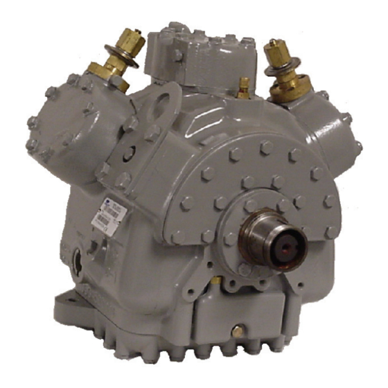
Page 10: Figure 1-1. Model 05G Compressor
COMPRESSOR WITH MOUNTING FLANGE (ULTRA TYPE SHOWN) COMPRESSOR WITHOUT MOUNTING FLANGE 1. Discharge Service Valve 7. Oil Level Sight Glass 2. High Pressure Connection 8. Bottom Plate 3. Low Pressure Connection 9. Oil Drain Plug 4. Suction Service Valve 10. Oil Pump (See Figure 1-3) 5. -
Page 11: Detailed Description
1.4 DETAILED DESCRIPTION 1.4.1 Service Valves The suction and discharge service valves used on the compressor are equipped with mating flanges for connection to flanges on the compressor. These valves are provided with a double seat and a gauge connection, which allows servicing of the compressor and refrigerant lines (See Figure 1-1). -
Page 12: Compressor Unloaders
1.5 COMPRESSOR UNLOADERS When the pressure behind the piston has been reduced sufficiently, the valve spring will force the piston bypass The compressor is equipped with unloaders for capacity valve back, opening the gas bypass from the discharge control. This consists of a self--contained, cylinder head manifold to the suction manifold. -
Page 13: Pressure--Operated Unloaders
The loaded cylinder bank will continue to operate fully loaded until the solenoid valve control device is energized and the gas bypass port is opened. Sealing Cap Pressure Differential Adjustment Screw Control Set Point Adjustment Nut Poppet Valve Piston Bypass Valve 1. -
Page 15: Compressor Replacement
SECTION 2 COMPRESSOR REPLACEMENT 2.1 COMPRESSOR REMOVAL 2.2.1 Installing Compressor Unloaders a. Remove the three socket head capscrews holding Refer to the operation and service manual covering the piston plug to cylinder head of the replacement equipment in which the compressor is installed for compressor. -
Page 16: Installing Compressor
2.2.2 INSTALLING COMPRESSOR g. Recheck compressor oil level. h. Check operation of compressor unloaders (if installed). WARNING Midseat service valves or by other means relieve pressure replacement compressor before removing plugs. CAUTION The high capacity oil pump must be set to rotate in the same direction as the crankshaft. -
Page 17: Compressor Maintenance
SECTION 3 COMPRESSOR MAINTENANCE 3.1 SHAFT SEAL RESERVOIR c. Inspect suction and discharge valve seats (on valve plate). The shaft seal reservoir will accumulate up to 3.5 d. If unloaders are installed, inspect operation of ounces of oil. It should be serviced (checked and unloader. -
Page 18: Oil Pump And Bearing Head
1 Capscrew 5 Lockwasher 9 Valve Plate Gasket 2 Cylinder Head 6 Discharge Valve Backer 10 Suction Valve 3 Cylinder Head Gasket 7 Discharge Valve 11 Suction Valve Spring 4 Capscrew 8 Valve Plate 12 Dowel Pin Figure 3-2. Cylinder Head & Valve Plate e. -
Page 19: Removal
3.5.1 Removal 3.5.3 Reassembly Remove eight capscrews and remove the oil pump a. Install the pump end thrust washer on the two dowel bearing head assembly, gasket and thrust washer. (See pins located on the bearing head. (See Figure 3-5.) Figure 3-5.) CAUTION Ensure that thrust washer does not fall off... -
Page 20: Reassembly
b. Lubricate the end of the crankshaft with clean oil. NOTE c. Using two long screwdrivers, pry out the shaft seal but Do not touch the sealing surfaces with your do not damage the gasket surface or the crankshaft. fingers. If the sealing surfaces become (See Figure 3-8) contaminated, clean with isopropyl alcohol and... -
Page 21: Crankshaft And Seal End Thrust Washer
be installed during compressor reassembly. (See Figure 3-11) d. Push the piston rods down so that the piston rings ex- tend below the cylinders. Remove and discard piston rings. Use only new rings when reassembling the compressor. (See Figure 3-12.) 3.7.2 Crankshaft and Seal End Thrust Washer 1 Bottom Plate 2 Oil Strainer... -
Page 22: Seal End Main Bearings
d. Measure side clearance between ring and ring groove in piston. Maximum dimensions are provided in Table 3-2. e. If parts are worn beyond limits, replace them in matched sets as specified above. f. Coat piston pins with compressor oil and reassemble pistons, pins, and connecting rods in matched sets. -
Page 23: Crankshaft And Seal End Thrust Washer
c. The compressor will be fitted with double ring pistons. be checked by using a small piece of stiff wire to en- sure that the spring mechanism can be depressed. Compression Ring Compression Ring Figure 3-18. Piston Rings Figure 3-19. Installing Pistons d. -
Page 24: Table 3-1. Torque Values
Table 3-1. Torque Values SIZE THREADS DIAMETER TORQUE RANGE USAGE PER INCH (INCHES) FT-- LB 1/16 27 (pipe) 5.5 to 7 0.8 to 1.0 Crankshaft Center Web Plug 27 (pipe) 8 to 16 1.1 to 2.2 Oil Return Check Valve -- Crankcase 7/16 8 to 14 1.1 to 1.9... -
Page 25: Figure 3-21. Piston Dimension (Wear Limits)
Table 3-2. Wear Limits MAXIMUM WEAR FACTORY MAXIMUM FACTORY MINIMUM BEFORE REPAIR PART NAME INCHES INCHES INCHES SEAL END End Play (Seal Removed) 0.034 0.8636 .013 0.3302 Main Bearing Diameter 1.8760 47.6504 1.8754 47.6352 .002 0.051 Main Bearing Journal Diameter 1.8732 47.5793 1.8725... - Page 27 INDEX Compresor Replacemant, 2--1 Service Valves, 1--3 Compressor Refernce Data, 1--1 Shaft Seal Maintenance, 3--3 Compressor Valves, 1--3 Shaft Seal Reservoir, 1--3 Cylinder Head and Valve Plate Maintenance, 3--1 Suction Strainer, 3--7 Lubrication System, 1--3 Torque Values, 3--8 Oil, 1--1 Oil Level, 2--2 Oil, Adding, 3--7 Oli Pump Maintenance, 3--2...
- Page 32 Fax: 1- -706- -355- -5435 11570 Mexico, D.F. P.O. Box 4805 Tel: (5255) 9126.0300 Syracuse, N.Y. 13221 U.S A Fax: (5255) 9126.0373 www.carrier.transicold.com A member of the United Technologies Corporation family. Stock symbol UTX ©2007 Carrier Corporation D Printed in U. S. A. 1207...