
Related Manuals for Samsung NX-N2


Summary of Contents for Samsung NX-N2
-
Page 1: User Manual
User Manual NX-N2 The color and the appearance may differ depending on the product, and the specifications are subject to change without prior notice to improve the performance. BN46-00400A-00... -
Page 2: Table Of Contents
Table Of Contents BEFORE USING THE Copyright PRODUCT Icons used in this manual Symbols for safety precautions Securing the Installation Space Precautions for storage Safety Precautions Electricity and Safety Installation and Safety Operation and Safety PREPARATIONS Checking the Components Checking the Components Parts Front view Reverse Side... - Page 3 User Settings Window Password Window Wake On LAN Wake on USB OSD Logo Upload Firmwre Update TROUBLESHOOTING Requirements Before Contacting Samsung Customer Service Center GUIDE Check the following. SPECIFICATIONS General Power consumption APPENDIX Contact SAMSUNG WORLD WIDE Responsibility for the Pay Service...
-
Page 4: Before Using The Product
© 2014 Samsung Electronics Samsung Electronics owns the copyright for this manual. Use or reproduction of this manual in parts or entirety without the authorization of Samsung Electronics is prohibited. The SAMSUNG logo is a registered trademark of Samsung Electronics. -
Page 5: Icons Used In This Manual
Before Using the Product Icons used in this manual The following images are for reference only. Real-life situations may differ from what is shown in the images. Symbols for safety precautions A serious or fatal injury may result if instructions are not followed. Warning Personal injury or damage to properties may result if instructions are Caution... -
Page 6: Securing The Installation Space
Before Using the Product Securing the Installation Space Ensure some space around the product for ventilation. An internal temperature rise may cause fire and damage the product. Be sure to allow the amount of space as shown below or greater when installing the product. -
Page 7: Safety Precautions
Before Using the Product Safety Precautions The following images are for reference only. Real-life situations may differ from what is shown in the images. Electricity and Safety Warning Do not use a damaged power cable or plug, or a loose power socket. An electric shock or fire may result. -
Page 8: Installation And Safety
The product may become damaged by an electric shock. Do not use the power cable for products other than authorized products supplied by Samsung. An electric shock or fire may result. Keep the power socket where the power cable is connected unobstructed. - Page 9 Before Using the Product Do not install the product on an unstable or vibrating surface (insecure shelf, sloped surface, etc.). The product may fall and break or cause a personal injury. Using the product in an area with excess vibration may damage the product ...
-
Page 10: Operation And Safety
SAMSUNG period of time) may seriously affect its performance. Be sure to consult Samsung Customer Service Center (page 69) before installation if you want to install the product at such a place. - Page 11 If water or any foreign substance enters the product, be sure to power off the product, remove the power cable, and contact Samsung Customer Service Center (page 69). Product failure, an electric shock or fire may result.
- Page 12 Before Using the Product Caution Disconnect the power cable from the power socket if you do not plan on using the product for an extended period of time (vacation, etc.). Otherwise, a fire may result from accumulated dust, overheating, an electric ...
- Page 13 Before Using the Product Do not place heavy objects on the product. Product failure or personal injure may result. Do not increase the volume too high when using headphones (earphones). Sound particularly at a higher volume could potentially affect long-term ...
-
Page 14: Preparations
Preparations Checking the Components 1.1.1 Checking the Components Contact the dealer from whom you purchased the product if any item is missing. The appearance of the components and items sold separately may differ from the image shown. Components Quick setup guide Warranty card User Manual... - Page 15 Preparations Items sold separately The following items can be purchased at your nearest retailer. LAN cable USB cable HDMI-DVI cable DVI cable DVI-RGB cable DP cable Mouse (USB) Keyboard Headphone 1 Preparations...
-
Page 16: Parts
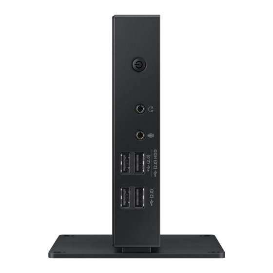
Preparations Parts 1.2.1 Front view The color and shape of parts may differ from what is shown. Specifications are subject to change without notice to improve quality. Ports Description Power on or off the product. Please press the button for two seconds. Connect to an audio output device such as headphones. - Page 17 Preparations Ports Description Connect to a USB device. Speaker 1 Preparations...
-
Page 18: Reverse Side
Preparations 1.2.2 Reverse Side The color and shape of parts may differ from what is shown. Specifications are subject to change without notice to improve quality. Ports Description Connect to a USB device. Connect to the monitor using the DP cable. Sound output through the [DP OUT] port is not supported. -
Page 19: Installation
Preparations Installation 1.3.1 Attaching the cradle The color and shape of parts may differ from what is shown. Specifications are subject to change without notice to improve quality. This product can be installed in portrait or landscape orientation. Vertical Type Horizontal Type 1 Preparations... -
Page 20: Attaching Products
VESA compliant. Using screws not compatible with the VESA standards may damage the product or cause the attachment to fall off. Samsung is not responsible for damages associated with not using VESA compliant parts. Do not use screws that do not comply with the VESA standards. -
Page 21: Anti-Theft Lock
Preparations 1.3.3 Anti-theft Lock An anti-theft lock allows you to use the product securely even in public places. The locking device shape and locking method depend on the manufacturer. Refer to the user guide provided with your anti-theft locking device for details. The lock device is sold separately. To lock an anti-theft locking device: Fix the cable of your anti-theft locking device to a heavy object such as a desk. -
Page 22: Using "Pcoip
Using "PCoIP" What is a "PC over IP"? Rack Mount Server Work Station The product receives images from the encoded file on the server PC via LAN and then decodes and displays the images on the connected display devices. If only one display device is connected to the DP port on the product, the product can support the single display at a maximum resolution of 2560 x 1600. -
Page 23: Connection To Use "Pcoip
Using "PCoIP" Connection to Use "PCoIP" Do not connect the power cable before connecting all other cables. Ensure you connect a source device first before connecting the power cable. 2.2.1 Connection Using the DP Cable DP OUT DP IN Connect the DP cable to the [DP OUT] port on the back of the product and the [DP IN] port on the Sound output through the [DP OUT] port is not supported. -
Page 24: Connecting To A Secondary Monitor
Using "PCoIP" 2.2.2 Connecting to a Secondary Monitor DVI-I OUT DVI IN RGB IN DVI-I OUT DVI-I OUT HDMI IN Connect the DVI, DVI-RGB or DVI-HDMI cable (sold separately) to the [DVI-I OUT] port on the back of the product and the [DVI IN], [RGB IN] or [HDMI IN] port on the PC. The [DVI-I OUT] port is for a secondary monitor. -
Page 25: Connecting To Headphones
Using "PCoIP" 2.2.3 Connecting to Headphones Connect the headphones to [ ] on the front of the product. 2.2.4 Connecting a Microphone Connect the microphone to [ ] on the front of the product. 2 Using "PCoIP"... -
Page 26: Lan Connection
Using "PCoIP" 2.2.5 LAN Connection Connect the LAN cable to the [LAN] port at the back of the product. 2 Using "PCoIP"... -
Page 27: Connecting Usb Devices
Using "PCoIP" 2.2.6 Connecting USB Devices (2.0) HDD (2.0) Connect USB devices to the ports on the front or back of the product. Keyboard and mouse devices are required to connect to [ (2.0)]. When connecting an external hard drive, use the [ (2.0) HDD] port. -
Page 28: Connecting The Power
Using "PCoIP" 2.2.7 Connecting the Power Connect the power cable to the DC power adapter. Then, connect the DC power adapter to the [DC 14V] port on the back of the product. Next, connect the power cable to the power outlet. DC 14V The input voltage is switched automatically. -
Page 29: Connect To The Host Pc Using A Lan Cable
Connect to the host PC using a LAN cable Host PC Rack Mount Server Work Station LAN Cable NX-N2 Host PC LAN Cable NX-N2 Connect the power cord to the power terminal at the back of the product. Connect the mouse and the keyboard to the USB ports. -
Page 30: On Screen Display (Osd)
Using "PCoIP" "PCoIP" 2.4.1 On Screen Display (OSD) The On Screen Display (OSD) local GUI is displayed to the user when the device is powered on and a PCoIP session is not in progress. The OSD lets the user connect to a host device through the Connect window. -
Page 31: Osd Options Menu
Using "PCoIP" 2.4.3 OSD Options Menu Selecting the Options menu will display a list of selections. The OSD Options menu contains: Configuration This option lets you configure various settings for the device such as network settings, session type, language, and other settings. Diagnostics ... -
Page 32: Configuration Window
Using "PCoIP" 2.4.4 Configuration Window Configuration option on the Administrative Web Interface and OSD lets you configure various settings for the device. The tabs in the Configuration window are: Network IPv6 SCEP Label Discovery Session ... - Page 33 Using "PCoIP" Network Tab You can configure the host and client network settings from the Initial Setup page or Network page. After you update the parameters on this page, click Apply to save your changes. The Network parameters can also be configured using the Administrative Web Interface. Figure 2-3: Network Configuration...
- Page 34 Using "PCoIP" Secondary DNS Server The secondary DNS IP address of the device. This field is optional. If the DNS server IP address is configured using the Connection Manager, the address may be set as an FQDN instead of an IP address. Domain Name ...
- Page 35 Using "PCoIP" IPv6 Tab IPv6 page lets you enable IPv6 for PCoIP devices connected to your IPv6 network. When you make a change to one of the settings on this page, you must reboot your device for the change to take effect. Figure 2-4: IPv6 Configuration...
- Page 36 Using "PCoIP" FQDN The fully qualified domain name for the host or client. If DHCPv6 is enabled, this field is automatically populated by the DHCPv6 server. Enable SLAAC Enable this field to set up stateless address auto-configuration (SLAAC) for your devices. Enable Manual Address ...
- Page 37 Using "PCoIP" Label Tab Label page is available from the host or client. The Label page lets you add information for the device. The Portal Label parameters can also be configured using the Administrative Web Interface. Figure 2-5: Label Configuration PCoIP Device Name ...
- Page 38 Using "PCoIP" Discovery Tab Use the settings on the Discovery page to erase the discovery of hosts and clients in your PCoIP system and dramatically reduce the configuration and maintenance effort for complex systems. This discovery mechanism is independent of DNS SRV discovery. For SLP discovery to work, routers must be configured to forward multicast traffic between subnets.
- Page 39 Using "PCoIP" Session Tab Session page lets you configure how the host or client device connects to or accepts connections from peer devices. The Session parameters can also be configured using the Administrative Web Interface. Figure 2-7: Session Configuration Connection Type ...
- Page 40 Using "PCoIP" When you select a View Connection Server type from the Session page, specific configuration options will appear. View Connection Server: Connect to the VMware VDI (Virtual Desktop Infrastructure) server. VMware VDI is a virtual desktop solution. DNS Name or IP Address: Enter the VMware View Connection Server's...
- Page 41 Using "PCoIP" Language Tab Language page lets you change the user interface language. This setting affects the local OSD GUI. It is only available on the client. The Language parameters can also be configured using the Administrative Web Interface. ...
- Page 42 Using "PCoIP" Power Tab Figure 2-11: Power Configuration OSD Screen-Saver Timeout (when not connected to a session): Connected monitors will go into standby mode if left idle for a specified period of time (in seconds). Enter "0" if you do not want to use the standby mode function. Display Suspend Timeout (when connected to a session): Connected monitors will go into standby ...
- Page 43 Using "PCoIP" Display Tab Display page lets you enable the Extended Display Identification Data(EDID) override mode. This function is only available through the OSD. Under normal operation, the in the host computer queries a monitor attached to the zero client to determine the monitor's capabilities.
- Page 44 Using "PCoIP" 1920x1080 @60 Hz 1856x1392 @60 Hz 1792x1344 @60 Hz 1680x1050 @60 Hz 1600x1200 @60 Hz 1600x900 @60 Hz 1440x900 @60 Hz 1400x1050 @60 Hz 1366x768 @60 Hz 1360x768 @60 Hz ...
- Page 45 Using "PCoIP" Audio Tab Configure the audio settings (e.g., mic and headphones). Figure 2-13: Audio Configuration Enable Local USB Audio Driver Sound will play from the internal speakers when playing music found on the server. e internal speakers. Sound output and connected devices ...
- Page 46 Using "PCoIP" Reset Tab Reset page lets you reset configuration and permissions to factory default values stored in onboard flash memory. Reset can also be initiated using the Administrative Web Interface. Resetting parameters to factory default values does not revert the firmware or clear the custom ...
-
Page 47: Diagnostics Window
Using "PCoIP" 2.4.5 Diagnostics Window Diagnostic menu contains links to pages with run-time information and functions that may be useful for troubleshooting. Diagnostic options in the OSD are a subset of those available through the Administrative Web Interface. Event Log Session Statistics PCoIP Processor Ping... - Page 48 Using "PCoIP" Clear Click to delete all event log messages stored on the device. Session Statistics Tab Session Statistics page lets you view current statistics when a session is active. If a session is not active, you can view the statistics from the last session. Session Statistics can also be viewed using the administrative web interface.
- Page 49 Using "PCoIP" PCoIP Processor Tab PCoIP Processor page lets you reset the host or client and view the uptime of the client PCoIP processor since the last boot. PCoIP Processor Uptime can also be viewed in the administrative web interface. Figure 2-17: PCoIP Processor Configuration...
- Page 50 Using "PCoIP" Ping Tab Ping page allows you to ping a device to see if it is reachable across the IP network. This may help you determine if a host is reachable. As a result of firmware releases 3.2.0 and later forcing the “do not fragment”...
-
Page 51: Information Window
Using "PCoIP" 2.4.6 Information Window Information page lets you see details about the device. The Administrative Web Interface shows version, VPD, and attached device information. The OSD lets you view the device version information. Version page lets you view the hardware and firmware version details for a device. Figure 2-19: Version Configuration... - Page 52 Using "PCoIP" Firmware Build Date Build date for the current firmware PCoIP Processor Family The Tera family name is displayed. Tera is a host processor from Teradici. This product uses a TERA2321 from the newer generation Tera2 host processor family and is displayed as Tera2.
-
Page 53: User Settings Window
Using "PCoIP" 2.4.7 User Settings Window User Settings page allows you to access tabs to define the Certificate Checking Mode, the mouse and keyboard settings, PCoIP protocol image quality, and display topology. The tabs in the User Settings menu are: Certificate Mouse Keyboard... - Page 54 Using "PCoIP" Mouse Tab Mouse page lets you change the mouse cursor speed settings for the OSD sessions. The OSD mouse cursor speed setting does not affect the mouse cursor settings when a PCoIP session is active unless the Local Keyboard Host Driver function is being used.
- Page 55 Using "PCoIP" Keyboard Tab Keyboard page lets you change the keyboard repeat settings for the OSD session. The keyboard settings do not affect the keyboard settings when a PCoIP session is active unless Local Keyboard Host Driver function is used. Refer to the "PCoIP Host Software for Windows User Guide: TER0810001"...
- Page 56 Using "PCoIP" Image Tab Image page allows you to make changes to the image quality of the PCoIP session. Figure 2-23: Image Configuration Image Quality Preference Use the slider to adjust the balance between image sharpness and smooth motion during a PCoIP session when network bandwidth is limited.
- Page 57 Using "PCoIP" Display Topology Tab To apply the Display Topology feature to a PCoIP session between a zero client and a PCoIP host, you must have the PCoIP host software installed on the host. Refer to the "PCoIP Host Software for Windows User Guide: TER0810001"...
- Page 58 Using "PCoIP" Alignment Select how you want displays A and B aligned when they are different sizes. This setting affects which area of the screen to use when you move the cursor from one display to the other. The alignment options that appear in the drop-down list depend on whether you have selected a horizontal or vertical display layout.
- Page 59 Using "PCoIP" Touch Screen Tab Touch Screen page allows you to configure and calibrate certain settings of an attached Elo TouchSystems touch screen display. Touch Screen page is only available through the OSD. It is not available in the Administrative Web Interface.
-
Page 60: Password Window
Using "PCoIP" 2.4.8 Password Window To use the Password function, configure Options for the zero client using PCoIP MC. Visit the Teradici Support Site: http://techsupport.teradici.com for further details. Password page lets you update the local administrative password for the device. The Password can be a maximum of 20 characters. - Page 61 Using "PCoIP" Figure 2-27: Authorized Password Reset Configuration Details on how to use PCoIP are subject to change without notice. To view the latest information, visit the Teradici website at http://www.teradici.com. 2 Using "PCoIP"...
-
Page 62: Wake On Lan
Using "PCoIP" 2.4.9 Wake On LAN This feature allows you to power on the product by sending a pre-determined command from an external system to the product over a network. Make sure the network is capable of data communication with the PC that sends the command to the product. -
Page 63: Wake On Usb
Using "PCoIP" 2.4.10 Wake on USB If you turn off the power after activating Wake On USB on the product administrative web page, the system switches to standby mode. The Wake on USB feature switches the system from standby mode to normal mode if a change to the keyboard or mouse input is detected. -
Page 64: Osd Logo Upload
Using "PCoIP" 2.4.11 OSD Logo Upload Using the OSD Logo Upload page, change the logo displayed on the Teradici OSD. Configuring the settings Set the product and PC IP addresses to enable the product to connect to the PC over a network. Enter the IP address set for the product in the URL address field on the PC to access the product administrative web page. -
Page 65: Firmwre Update
Using "PCoIP" 2.4.12 Firmwre Update Using the Firmwre Update page, change the Teradici Firmware. Configuring the settings Set the product and PC IP addresses to enable the product to connect to the PC over a network. Enter the IP address set for the product in the URL address field on the PC to access the product administrative web page. -
Page 66: Troubleshooting Guide
Troubleshooting Guide Requirements Before Contacting Samsung Customer Service Center 3.1.1 Check the following. Installation issue Issues Solutions The product cannot power on. Check that the power cable is connected properly. (Refer to "2.2.7 Connecting the Power") Sound issue Issues Solutions There is no sound. -
Page 67: Specifications
The above specifications are subject to change without notice to improve quality. This device is a Class A digital apparatus. (USA only) Dispose unwanted electronics through an approved recycler. To find the nearest recycling location, go to our website: www.samsung.com/recyclingdirect or call, (877) 278 - 0799 4 Specifications... -
Page 68: Power Consumption
Specifications Power consumption Normal operation mode Stand by PowerSaver Power off (Wake On USB) Typical Rating Power lamp Power Less than Less than Less than Less than Consumption 30 W 1.1 W 0.3 W The power consumption level can vary in different operating conditions or when settings are ... -
Page 69: Appendix
Appendix Contact SAMSUNG WORLD WIDE If you have any questions or comments relating to Samsung products, please contact the SAMSUNG er . customer care cent NORTH AMERICA U.S.A 1-800-SAMSUNG (726-7864) http://www.samsung.com/us CANADA 1-800-SAMSUNG (726-7864) http://www.samsung.com/ca (English) http://www.samsung.com/ca_fr (French) LATIN AMERICA... - Page 70 0810 - SAMSUNG http://www.samsung.com (7267864, € 0.07/min) BELGIUM 02-201-24-18 http://www.samsung.com/be (Dutch) http://www.samsung.com/be_fr (French) BOSNIA 051 331 999 http://www.samsung.com BULGARIA 07001 33 11, share cost tariff http://www.samsung.com/bg CROATIA 062 SAMSUNG (062 726 786) http://www.samsung.com/hr CYPRUS 8009 4000 only from landline http://www.samsung.com/gr Appendix...
- Page 71 Appendix EUROPE CZECH 800 - SAMSUNG (800-726786) http://www.samsung.com Samsung Electronics Czech and Slovak, s.r.o. V Parku 2343/24, 148 00 -Praha 4 DENMARK 70 70 19 70 http://www.samsung.com EIRE 0818 717100 http://www.samsung.com ESTONIA 800-7267 http://www.samsung.com/ee FINLAND 030-6227 515 http://www.samsung.com FRANCE 01 48 63 00 00 http://www.samsung.com/fr...
- Page 72 Appendix EUROPE SLOVAKIA 0800 - SAMSUNG (0800-726 786) http://www.samsung.com SPAIN 902172678 http://www.samsung.com SWEDEN 0771 726 7864 (SAMSUNG) http://www.samsung.com SWITZERLAND 0848-SAMSUNG http://www.samsung.com/ch (7267864, CHF 0.08/min) (German) http://www.samsung.com/ch_fr (French) 0330 SAMSUNG (7267864) http://www.samsung.com ARMENIA 0-800-05-555 http://www.samsung.com AZERBAIJAN 088-55-55-555 http://www.samsung.com BELARUS 810-800-500-55-500 http://www.samsung.com...
- Page 73 1800 266 8282 INDONESIA 0800-112-8888 (Toll Free) http://www.samsung.com/id (021) 56997777 JAPAN 0120-327-527 http://www.samsung.com MALAYSIA 1800-88-9999 http://www.samsung.com/my NEW ZEALAND 0800 SAMSUNG (0800 726 786) http://www.samsung.com/nz PHILIPPINES 1-800-10-7267864 [PLDT] http://www.samsung.com/ph 1-800-8-7267864 [Globe landlineand Mobile] 02-4222111 [Other landline] SINGAPORE 1800-SAMSUNG (726-7864) http://www.samsung.com/sg TAIWAN 0800-32-9999 http://www.samsung.com/tw...
- Page 74 NIGERIA 0800-726-7864 http://www.samsung.com/africa_en MOZAMBIQUE 847267864 / 827267864 http://www.samsung.com RWANDA 9999 http://www.samsung.com SENEGAL 800-00-0077 http://www.samsung.com/africa_fr SOUTH AFRICA 0860 SAMSUNG (726 7864) http://www.samsung.com SUDAN 1969 http://www.samsung.com TANZANIA 0685 88 99 00 http://www.samsung.com UGANDA 0800 300 300 http://www.samsung.com ZAMBIA 0211 350370 http://www.samsung.com...
-
Page 75: Responsibility For The Pay Service (Cost To Customers)
use of supplies or separatly sold product unspecified by Samsung. repair from a person besides an engineer of outsourcing service company or partner of Samsung Electronics Co., Ltd. remodeling or repairing the product by customer. -
Page 76: Others
Appendix Others If product fails by natural disaster (lightning, fire, earthquake, flood damage, etc). If consumable components are all used up (Battery, Toner, Fluorescent lights, Head, Vibrator, Lamp, Filter, Ribbon, etc.). If customer requests a service in case the product has no defect, service fee may be charged. So please read User Manual first. -
Page 77: Correct Disposal
Appendix Correct Disposal Correct Disposal of This Product (Waste Electrical & Electronic Equipment) (Applicable in countries with separate collection systems) This marking on the product, accessories or literature indicates that the product and its electronic accessories (e.g. charger, headset, USB cable) should not be disposed of with other household waste at the end of their working life. -
Page 78: Index
Index Symbols "PCoIP" Checking the Components Connect to the host PC using a LAN cable Connection to Use "PCoIP" Contact SAMSUNG WORLD WIDE Copyright Correct Disposal General Installation Parts Power consumption Requirements Before Contacting Samsung Customer Service Center Responsibility for the Pay Service (Cost to...