Table of Contents
Advertisement
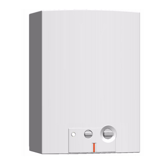
520 HN
Flow Modulated with Hydro-generated Ignition
Suitable for heating potable water only - Not approved for space heating purposes
(Intended for variable flow applications with steady cold water inlet temperatures)
520-HN-N
520-HN-L
Warning: If the information in this manual is not
followed exactly, a fire or explosion may result
causing property damage, personal injury or death.
Do not store or use gasoline or other flammable
vapor and liquids in the vicinity of this or any other
appliance.
Improper
installation,
service or maintenance can cause injury or
property damage. Refer to this manual. For
assistance or additional information consult a
qualified installer, service agency or the gas
supplier.
In the Commonwealth of Massachusetts this
product must be installed by a licensed plumber or
gas fitter.
Upon completion of the installation, these
instructions should be handed to the user of the
appliance for future reference.
adjustment,
alteration,
What to do if you smell gas
• Close gas valve. Open windows.
• Do not try to light any appliance.
• Do not touch any electrical switch; do not use any
phone in your building.
• Immediately call your gas supplier from a neighbor's
phone. Follow the gas supplier's instructions.
• If you cannot reach your gas supplier, call the fire
department.
• Installation and service must be performed by a
qualified installer, service agency or the gas supplier.
Advertisement
Table of Contents

Related Manuals for Bosch 520-HN-N


Summary of Contents for Bosch 520-HN-N
- Page 1 Flow Modulated with Hydro-generated Ignition Suitable for heating potable water only - Not approved for space heating purposes (Intended for variable flow applications with steady cold water inlet temperatures) 520-HN-N 520-HN-L Warning: If the information in this manual is not...
-
Page 2: Table Of Contents
Index Index Warning Warning Warning: The heater must be isolated Appliance details from the gas supply piping system 520 HN specifications (Technical data) during any pressure testing of that Unpacking the 520 HN heater system at test pressures equal to or General rules to follow for safe operation more than 0.5 psig. -
Page 3: Appliance Details
Water protection • Propane: 10.5” - 14” water column IP X4. • Natural Gas: 5.7” - 14” water column. Accessories (Bosch part #) * To measure Gas Pressure, see Measuring Gas Pressure, chapter 3.7. • Freeze prevention kit (7709003775) • Pressure relief valve (FWL-2). -
Page 4: Unpacking The 520 Hn Heater
• Incandescent particle tray. has been underwater. Do not lose this manual, there is a charge for a BOSCH is constantly improving its replacement. products, therefore specifications are Please complete and return the enclosed product subject to change without prior notice. -
Page 5: Dimensions And Installation Clearances
Appliance details Dimensions and installation clearances 8,66" (220) 4,92"(125) 1,97" (50) 3,82" (97) 6720608036-01.2Av Fig. 3 Dimensions in Inches and (mm) Heat exchanger Burner Dimensions inches (mm) Flow control knob Water valve 520 HN Gas connection Ignition unit 16.73” (425) Power adjustment knob LED indicator for burner status 25.75”... -
Page 6: Installation Instructions
Failure to follow venting plumber or gas technician. requirements may result in dangerous Please contact Bosch Water Heating with any exhaust gases entering living space. questions. B Minimum vent pipe diameter: 5 inches... - Page 7 Installation instructions B An approved gas vent connector must be attached to the top of the water heater and rise vertically at least 5” X 6” ADAPTOR 12" before entering into an approved gas vent USED AT HIGH connector elbow. ALTITUDE B The minimum vertical gas vent height allowed is 6 feet;...
- Page 8 Installation instructions Masonry chimney GAS VENT TERMINATIONS FOR LISTED VENT CAPS Masonry chimneys shall be built and installed in Roof pitch H (minimum) feet meters accordance with NFPS 211 or local codes. A minimum Flat to 6/12 0.30 5" diameter gas vent pipe (metal double wall Type B), 6/12 to 7/12 1.25 0.38...
-
Page 9: Combustion Air Requirements
Installation instructions Combustion air requirements your openings by 400% if your louvers are wood and by 135% if your louvers are metal. Refer to the National The Protankless water heater holds cold water in its Fuel Gas Code for complete information. In buildings of copper heat exchanger and water valve when not in use. - Page 10 Installation instructions Mounting heater. Warning: B Do not install this appliance on a carpeted wall. The heater must be mounted on a wall using appropriate anchoring materials. If wall is a stud wall sheathed with plasterboard, it is recommended that support board(s), either 1x4’s or 1/2"...
- Page 11 Installation instructions Gas piping & connections B Install a union when connecting gas supply. B Attach the appliance regulator to the inlet gas pipe. Before connecting the gas supply, check the rating B The minimum diameter required for any appliance plate on the right side of the heater to be sure that the connector used is ¾”...
- Page 12 Installation instructions FOR NATURAL GAS Maximum Capacity of pipe in Cubic Feet of Gas per Hour for Gas Pressure of 0.5 Psig or less and a Pressure drop of 0.3 in Water Column (0.75mbar).(Based on a 0.60 Specific Gravity Gas) Btu numbers given in thousands. Copper tubing is prohibited for use with Natural Gas in the Commonwealth of Massachusetts and not recommended elsewhere.
-
Page 13: Measuring Gas Pressure
Installation instructions Measuring gas pressure Although water piping throughout the structure may be other than copper, we require that copper piping or Connecting manometer suitably rated stainless steel flex line piping be used for at least three feet before and after the heater (follow B Shut off gas. -
Page 14: Recirculation Application
The 520 HN must be plumbed in line supply and call a qualified service technician. before the mini-tank water heater. Contact Bosch Attempted forceful repair may result in a fire or Water Heating if further instruction is needed. -
Page 15: Lighting Instructions
Operation instructions Lighting instructions To turn off appliance B 1. STOP! Read the previous safety information. B Set the ON/OFF switch to the position OFF B 2. The gas valve must be shut off by putting the ON/ OFF switch to position OFF . -
Page 16: Power Adjustment Knob
Operation instructions B Turning the flow control knob clockwise restricts water flow. This provides higher temperature because the water is moving slower, spending more time over the burner flames. Turning flow control knob fully clockwise also lowers the activation rate (water flow needed to turn the heater on) to 0.5 gpm. -
Page 17: Maintenance And Service
If the set screws are seized, STOP and call maintenance. Bosch tech support before proceeding. Forcing and breaking seized set screws may damage the water valve The 520 HN requires periodic maintenance. The time and gas valve assemblies. Remove the water valve by maintenance intervals below should keep the unit pulling it to the right. -
Page 18: Main Burners
Maintenance and service Main burners 10. Make sure there are no leaks and the solution is flowing from the descaling reservoir through the heat The main burner flames should be blue, with a more exchanger and returning to the reservoir. intense blue cone in the center core. -
Page 19: Troubleshooting
• 3. Measure voltage at hydrogenerator. Disconnect the wire connector at hydrogenerator and measure • 10. If heater still does not spark, contact Bosch tech- voltage on hydrogenerator side of connector. nical support. – a. If the wires from the hydrogenerator are black and red, the voltage should be at least 1.3VDC. -
Page 20: Pilot Lights, But Burners Will Not Come On
Troubleshooting – e. Verify that gas shut off valves are open. Gas location of burner electrovalve). Inspect terminals for must be supplied to heater. corrosion. To clean terminals, remove the spade connectors and clean with a pencil eraser. – f. Measure gas pressure at inlet tap with manome- ter. -
Page 21: Hot Water Temperature Fluctuates At Tap
Troubleshooting or service person for help correcting a plumbing clockwise for lower hot water temperatures. See crossover. chapter 4.5. problem persists, www.boschpro.com for service bulletin CT-07. 3. The minimum water pressure required is 30psi. For installation on a well system with use of a pressure tank, 4. -
Page 22: Water Is Not Hot Enough
Troubleshooting the water heater should be cleaned and inspected. See 3. Inspect the water path outside the heater for chapter 5.2. obstructions. Make sure all showerheads, faucet aerators and whole house filters are clear of debris. 5. If the water has a high mineral content, the heat exchanger may be scaled internally. -
Page 23: Protecting The Environment
Protecting the environment 7 Protecting the environment Packing The packing box may be fully recycled as confirmed by the recycling symbol Components Many parts in the heater can be fully recycled in the end of the product life. Contact your city authorities for information about the disposal of recyclable products. -
Page 24: Interior Components And Diagram Parts List
Interior components and diagram parts list Interior components and diagram parts list Interior components 6720608036-04.3AL Fig. 27 Functional scheme Heat exchanger Flexible hot outlet Burner Power adjustment knob Ignition unit Pilot burner Flow control knob on/off button Water valve Gas connection Flexible cold inlet 6 720 644 942... -
Page 25: Components Diagram
Interior components and diagram parts list Components diagram 6720608036-05.3 JF Fig. 28 Components Diagram 6 720 644 942... -
Page 26: Parts List
Interior components and diagram parts list Parts list Item Description Reference Front cover 8 705 431 415 0 Shield 8 705 506 912 0 Trade mark badge 8 701 103 135 0 Flow control knob 8 702 000 297 0 Power adjustment knob 8 702 000 295 0 Draft Diverter... -
Page 27: Fifteen Year Limited Warranty
Bosch Thermotechnology Corporation. However, all • 2. to damage or abuse, accident, neglect or freezing replacements are made subject to validation by Bosch and other acts of nature; Thermotechnology Corporation of in-warranty cover- age. The damaged or defective item must be made •... - Page 28 Installation manual should be left with the owner after the installation is tested and completed BOSCH THERMOTECHNOLOGY CORP. 50 Wentworth Avenue Bosch Termotecnologia SA Londonderry, NH 03053 Estrada de Cacia Tel. 866-330-2730 3800 - 533 Cacia - PORTUGAL www.boschpro.com Recycled paper © 2010 Bosch Thermotechnology Corp., Londonderry, NH all rights reserved...