Advertisement
Advertisement
Table of Contents

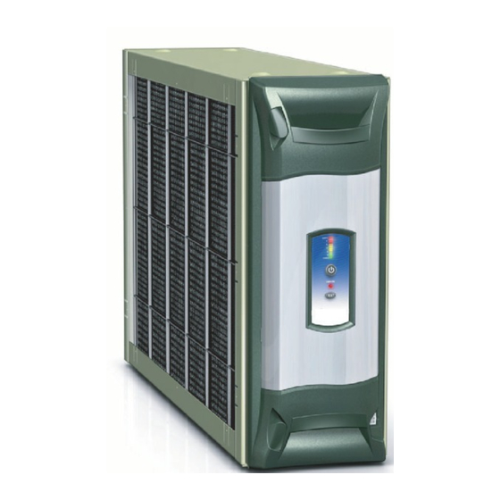
Summary of Contents for American Standard IFD AIR CLEANER
- Page 1 IFD AIR CLEANER SERVICE MANUAL PUB NO. 34-3446-01...
-
Page 2: Theory Of Operation
To reduce the risk of electric shock, do not perform any servicing other than that contained in these operating instructions unless you are qualified to do so. © 2005 American Standard Inc. All Rights Reserved... - Page 3 Service Manual FIELD CHARGER IONIZER PINS ARE POSITIVE CHARGED. AT THE NORMAL POWER SETTING THE IONIZER PINS WILL HAVE 9,600 VOLTS DC APPLIED TO THEM. THE POWER SETTING CAN BE CHANGED IN THE SET UP MODE OF OPERATION. COLLECTOR CELLS ARE INSULATED CELLS WITH ONE SIDE OF THE CELL POSITIVELY CHARGED AND THE OTHER SIDE OF THE CELL NEGATIVELY CHARGED.
- Page 4 Service Manual COLLECTOR CELL CONSTRUCTION Collector cells start out as a strip of corrugated box plastic strips. On the top and bottom of the strip a conductive ink strip is applied. These inked plastic strips are then glued together, one on top of the other forming the collector cells.
- Page 5 Service Manual Collector Cell Guide Strips Collector Cell CAUTION Do Not expose filter to UV light. UV light can cause plastic material to deteriorate which may lead to filter damage...
-
Page 6: Electrical Connections
NOTE: If Volt meter reads above 10 VAC, reverse the 24 Volt AC leads coming from the wall mounted trans- former to the Electronic Air Cleaner cable plug. TRANSFORMER GROUND (BLK) BLUE © 2005 American Standard Inc. All Rights Reserved... -
Page 7: Air Cleaner Operation
Service Manual SET-UP MODE OF OPERATION To enter the Set-up Mode press and hold both the Power and Reset buttons for a minimum of 5 seconds. The display will go blank and then the programmed settings are displayed. If this is the desired setting or at any time you want to exit the set-up mode, press and hold BOTH the Power and filter Reset buttons for a minimum of 5 seconds to exit. -
Page 8: Setting The Power Level
Service Manual SETTING THE POWER LEVEL LitePort DATA All electronic air cleaners produce a small amount of When the air cleaner has detected a fault and it is flashing it’s ozone that is within established limits. Some customers three RED LEDs on and off it will also be sending the fault data may notice an odor especially at high altitudes and low air to the pre-filter LED causing it to flash on and off. - Page 9 Service Manual SERVICE FAULT CODES YEL-1 YEL-2 YEL-3 YEL-4 RED-1 RED-2 RED-3 PROCEDURE No Fault Detected Input AC Voltage too Low HV OUTPUT VOLTAGE FAULT HV off when it should be on HV too LOW HV too HIGH Repetitive Arcing INPUT CURRENT FAULTS Input Current off when it should be on Input Current too LOW...
- Page 10 Service Manual TESTING COMPONENTS USING THE UNIT’S OWN MICRO & LEDs There are four tests that can be performed in the field. These Tests are for testing the High Voltage Relay, LEDs, High Voltage Output and the Thermostat Inputs. To enter the TEST Mode of this control perform the following. 1.Push and hold the Power Button until all ten LED come on, then release the Power Button .
- Page 11 Service Manual Test Yellow LED Description HV Supply output should be off. Indicate a fault if the HV Output = 0V 1st Yellow input current and HV checked are out of range. HV Supply output should be 9.6KV. Indicate a fault if the HV Output = 9.6KV 2nd Yellow input current and HV checked are out of range.
- Page 12 Service Manual the High Voltage Probe and compatible volt/ohm meter TESTING THE POWER DOOR per their manufactures instructions. HIGH VOLTAGE POWER SUPPLY Tools Required A High voltage Probe and a compatible Volt /Ohm Meter or a Screwdriver, Jumper Wire with Alligator Clips on each end, tape and dry paper.
-
Page 13: Fuse Replacement
Service Manual CAUTION HIGH VOLTAGE PRESENT FOR THIS TEST FUSE REPLACEMENT 5. Turn on the air cleaner, and then enter the Set Up A fuse, located inside the power door, protects the power Mode by pushing and holding both the Power button supply components against damaging electrical currents. - Page 14 Service Manual PRESSURE DROP AT SPECIFIC AIRFLOW PER MODEL 400 CFM 600 CFM 800 CFM 1000 CFM 1200 CFM 1400 CFM 1600 CFM 1800 CFM 2000 CFM *FD145ALFR 0.04 0.09 0.14 0.20 0.27 *FD175ALFR 0.03 0.06 0.10 0.14 0.19 0.24 0.30 *FD210ALFR 0.02...
- Page 15 Service Manual CAUTION High Voltage is present within the air cleaner for operation. CLEANING THE FIELD CHARGER Before removing the door, turn the power off and wait at Turn off the air cleaner and remove the power door. least 15 seconds to allow voltage to discharge. Bend the field charger metal locking tabs down against the case.
- Page 16 Indoor Blower ON 1. This indicates service is needed. three Red LEDs Flashing See Service Facts for fault code information. American Standard Inc. 6200 Troup Highway Tyler, TX 75707 For more information contact your local dealer (distributor)


