
Summary of Contents for Tiger 370 CNC--MR
- Page 1 USE AND MAINTENANCE MANUAL TIGER 370 CNC- -MR YEAR OF MANUFACTURE: ______________...
- Page 3 61045 Pergola (PU) ITALIA Tel. 072173721- - Fax 0721734533 ereby declares that the circular sawing machine: Machine model: TIGER 370 CNC- -MR Serial number: Year of manufacture: is in specification with the following directives: • DIRECTIVE EEC MACHINES DIRECTIVE 2006/42/CE •...
-
Page 5: Table Of Contents
......2- - 1 TIGER 370 CNC- -MR model .... - Page 6 Pneumatic diagram TIGER 370 CNC- - MR ..6- - 1 Pneumatic diagram TIGER 370 CNC- - FE HR ..6- - 2 APS/P drive for step motors .
- Page 7 Base ........6- - 42 Fixed worktable .
- Page 8 The role of the operator ......8- -1 Maintenance requirements ..... . 8- - 2 General maintenance .
- Page 9 Roller table ........11- - 3 Can of emulsible oil .
-
Page 11: Introduction And Technical Specifications
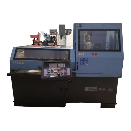
TIGER 370 CNC---MR is rugged, quiet and safe. It cuts various kinds of material, with very little scrap and great applicative flexibility cutting copper, brass and bronze. -
Page 12: Machine Specification
5,74 The “air consumption” value refers to standard conditions (temperature 0° and N.B. - -3 pressure 1.013 bar, i.e. density 1.3 x 10 Kg/l) where 1 Kg/min. = 772 Nl/min. Use and maintenance manual TIGER 370 CNC-- MR 1- -2... -
Page 13: Vice
LUBRICANT/COOLANT FLUID AND OIL Lubricant/coolant fluid (oil concentration 5---6%) capacità Lt. Oil for transmission box capacità Lt. VICE Vice max. opening CUTTING CAPABILITY Model Blade diameter 0° 180 x 100 45° ' 70 x 100 45° a 70 x 100 60°... -
Page 14: Dimensions
IP 54 protection rating (total against contact with live parts, water sprayed from all directions, with shaft oil seal). Conforming to CEI norms, publication: IEC 34 of 01/07/1985. Dimensions MACHINE INSTALLED Work table height 1000 Weight 1060 Use and maintenance manual TIGER 370 CNC-- MR 1- -4... - Page 15 Introduction and technical specifications 1- -5...
-
Page 16: Functional Parts
Functional parts TIGER 370 CNC- -MR model In order for the user to move towards a full understanding of how the machine works, which is described in detail in the chapter 5, this chapter deals with the main units and their locations. -
Page 17: Cutting Head
“lead nut” fixed to the work table on which a mobile jaw is mounted. The vice is operated manually by a handwheel and locked by a Pneumatic cylinder. Use and maintenance manual TIGER 370 CNC-- MR 2- -2... -
Page 18: Control Panel
Control Panel The control panel has a protection rating of IP 54 and contains the electronic equipment. Access to the control panel is protected by a safety panel mounted on hinges and fastened with screws, specially designed to prevent tampering. The control panel swivels on two articulated joints so that it can be positioned by the operator for greater ease---of---use and safety. -
Page 19: Base
This unit features a large coolant collection surface which conveys the coolant to the rear tank via the tank cover, and a swarf collection drawer. An electric pump is housed inside the tank which draws the clean fluid from the filter system. Use and maintenance manual TIGER 370 CNC-- MR 2- -4... -
Page 20: Safety And Accident Prevention
Safety and accident prevention The TIGER 370 CNC---MR has been designed and produced in accordance with European standards. For the correct use of the machine we recommend that the instructions contained in this chapter are carefully followed. Use of the machine The TIGER 370 CNC---MR circular saw is designed to cut exclusively non---fer- rous profiles and solid metal sections. -
Page 21: Recommendations To The Operator
Before starting cutting operations, support the material at both ends of the machine using the support arm --- standard, or OPTIONAL acces- sories such as the feed and discharge roller tables shown in the diagram below. Use and maintenance manual TIGER 370 CNC-- MR 3- -2... - Page 22 FEED ROLLER TABLE DISCHARGE ROLLER TA- mm. 1500 mm. 1500 Any maintenance work on the hydraulic or pneumatic systems must be carried out only after the pressure in the system has been released. The operator MUST NOT perform any risky operations or those not required for the machining in course (e.g.
-
Page 23: Machine Safety Devices
EEC Directive No. 89/656 and No. 89/686 on the use of personal protection de- vices. ENVIRONMENTAL PROTECTION EEC Directive No. 75/442 on waste disposal. EEC Directive No. 75/439 on the disposal of used oil. Use and maintenance manual TIGER 370 CNC-- MR 3- -4... -
Page 24: Protection Against Accidental Contact With The Blade
When the guards are returned to their original position the machine must be reset in order to resume work”..Emergency devices applicable to the TIGER 370 CNC---MR: 1. Emergency stop: a non---return mushroom---head pushbutton, colour red on yellow background, is located on the control panel of the machine. -
Page 25: Noise Level Of The Machine
CHINES DIRECTIVE 2006/42/CE , we are listing the standards that specify noise levels for machine tools. This chapter also reports the noise levels produced by the TIGER 370 CNC---MR during its various operating phases and the methods used for measuring these levels. The Italian standard governing this aspect is D.M.n.277/91 drawn from EEC Directives 80/1107, 82/605, 83/477, 86/188, 88/642,... -
Page 26: Noise Level Values
The following text contains a list of the applied standards and the results of the electromagnetic compatibility testing of machine model TIGER 370 CNC---MR; Test report no. 120101. Emissions CEI EN 61000- -6- -4 (2002) Electromagnetic Compatibility (EMC) - - Generic stan- dard regarding emissions. - Page 27 IMMUNITY TO CONDUCTED ELECTROMAGNETIC FIELDS Gate Test levels Evaluation criterion Result A.C. power supply in- Complies IMMUNITY TO IRRADIATED ELECTROMAGNETIC FIELDS Gate Test levels Evaluation criterion Result Enclosure 10 V/m Complies Use and maintenance manual TIGER 370 CNC-- MR 3- -8...
-
Page 28: Machine Installation
Machine installation Packaging and storage MEP S.p.A. use packing materials that guarantee the integrity and protection of the machine during its transport to the customer. The type of packing differs according to the size, weight and destination. Therefore the customer will receive the machine in one of two following ways: 1. - Page 29 To install the machine, first remove the packing, paying particular attention not to cut any electric wires or hydraulic hoses; if necessary use pliers, a hammer and a cutter. Open crate in the illustrated order: Use and maintenance manual TIGER 370 CNC-- MR 4- -2...
- Page 30 1. remove nails and lift the top of the cage; 2. remove nails and lower walls; 3. remove heat---shrink covering; 4. remove the straps; 5. remove nails from pallet securing planks and remove planks; 6. remove the front panel and insert fork tines. To locate the machine in the workplace, the machine dimensions and necessary operator working space, including the spaces laid down in safety standards, must be taken into account.
-
Page 31: Anchoring The Machine
± 10%. Check list Before starting installation, check that all the accessories, whether standard or optional, supplied with the machine are present. The basic version of the TIGER 370 CNC---MR is supplied complete with: CHARACTERISTICS... - Page 32 CHARACTERISTICS Fully encased model to provide operator safety, sound insulation and the possibility of working with large quantities of liquid HSS disk ø 370 x 32 x 3 for steel HM disk ø 400 x 32 x 3.6 for aluminium and light alloys Cabinet for electric and electronic equipment with fully identifiable wiring, door--- locking switch with padlockable device, emergency device, motor overload cut---out, minimum voltage coil and protection against a missing phase...
-
Page 33: Connection To The Compressed Air Supply
- neutral. Use and maintenance manual TIGER 370 CNC-- MR 4- -6... - Page 34 " Insert the plug in the socket, ensuring that the mains voltage is the same as that for which the machine has been setup. VOLT ? VOLT ? " To switch on the machine, turn the main switch located at the rear, on the right---hand side of the electric cabinet;...
- Page 35 The sawing machine is now ready to start the work for which it was designed. Chapter 5 provides a detailed description of the various functions of the machine and its operating cycles. Use and maintenance manual TIGER 370 CNC-- MR 4- -8...
-
Page 36: Description Of Machine Operation
The figure below shows the control panel of TIGER 370 CNC---MR: Key for control console keyboard On key: enables machine operation... - Page 37 Gun sprays lubricant/coolant fluid even stop immediately. To reset the emergen- when the machine is stopped cy, rotate the actuator by 45 ° Use and maintenance manual TIGER 370 CNC-- MR 5- -2...
- Page 38 Jet of lubricant/coolant fluid from taps, No lubricant/coolant fluid jet only when the cycle has started Button for memorizing the FCTI (Head Button for memorizing the FCTA (Head Upstroke Limit) Downstroke Limit) Button to open and close the timed door Chip discharger unit in manual mode of the cutting head Chip discharger unit deactivated...
-
Page 39: Basic Instructions For Carrying Out A Cutting Cycle
Basic instructions for carrying out a cutting cycle Manoeuvring the cutting head In the TIGER 370 CNC---MR model, it is possible to move the cutting head with up and down buttons, shown in the key of the control panel in this chapter. - Page 40 However, to ensure that the workpiece is securely clamped in the vice, proceed as follows: " make sure the workpiece dimensions do not exceed the machine’s cutting ca- pacity; " make sure the piece is correctly supported on both sides of the machine; "...
-
Page 41: Lubricant/Coolant Fluid Supply
" that the speed selected is right for the kind of piece to be cut; " that all protections are in place and correctly locked; " lubricant/coolant level and activation of the electropump; " the blade downstroke speed must be correct. Use and maintenance manual TIGER 370 CNC-- MR 5- -6... -
Page 42: Starting Up The Machine
Starting up the machine When switching on the machine, proceed as follows: " press the ON button. " Press RESET twice. The display shows the introductory and starting SCREEN. " To continue press F9. " The display suggests ZERO SETTING the machine. To carry out this opera- tion, press F6. -
Page 43: Semi- -Automatic Operating Cycle
Amperometer T =00,00 Partial cutting time TT=00,00 Total machine time for the cutting cycle Clamping the work piece in the vice " Release the protection by pressing the relevant key; Use and maintenance manual TIGER 370 CNC-- MR 5- -8... - Page 44 " open the vice by rotating the handwheel anti---clockwise and position the workpiece between the jaws. " Bring the moveable jaw to within 2÷3 mm of the workpiece by rotating the handwheel clockwise. 2---3 mm " Block the piece by means of the pneumatic cutting vice block, by pressing the close cutting vice button.
- Page 45 " Adjust the head descent speed potentiometer to 0 to avoid undesirable start- ing speeds. Cutting " Close the protection and press the reset button; " Enable motor rotation by activating the blade motor selector on the control console; Use and maintenance manual TIGER 370 CNC-- MR 5- -10...
- Page 46 " start operation. At this stage it is possible to adjust, according to the type of material, the 2 N.B. parameters which influence the cut: the disk rotation speed and the head downstroke speed, through the relative potentiometers on the control panel. Now the blade starts, the cutting cylinder is under pressure and the lubricant/ coolant supply starts.
-
Page 47: Automatic Operating Cycle
1 MEASUREMENT and 1 QUANTITY of cuts to be carried out. ING THE AUTOMATIC This possibilty has been included to avoid multiple programming procedures when CYCLE these are not necessary. Use and maintenance manual TIGER 370 CNC-- MR 5- -12... - Page 48 F9 = MAIN MENU: press this button to return to the working mode selection menu. F8 = BLADE THICKNESS: this option gives access to programming of the BLADE THICKNESS. This parameter is very important because the bar infeed system oper- ates in zero setting mode, therefore the value of the scrap produced by the disk must OPERATING BUT- be added to the size of the piece to be processed.
- Page 49 F6 = EXEC. STEP/CONT Programming cuts Once the material to be cut has been inserted and blocked, bring the cutting head to the FCTI (Head Upstroke Limit) position, set the cutting dimension indicated Use and maintenance manual TIGER 370 CNC-- MR 5- -14...
-
Page 50: Single Program
on the display as Measure, and the amount of pieces to be cut Prog. cuts. OPERATING CYCLE FCTI θ° = AUTOMATIC F = 153 PGR. NO MEASUR. CUTS PROG. 512,8 2343 SINGLE CYCLE θ CUTS RUN/PROG=PROGRAMMING PROG. F0 = PGR. SINGLE CUTS F9 = MAIN MENU F8 = BLADE THICKNESS... - Page 51 Digit 100, pressing in order buttons “1” “0” “0”; then press ENTER again. With this operation you will obtain two results: Use and maintenance manual TIGER 370 CNC-- MR 5- -16...
- Page 52 1) the new value is memorized; 2) the reverse moves to NR PGR. OPERATING CYCLE AUTOMATIC FCTI θ° = F = 153 PGR. NO MEASUR. CUTS PROG. 905,7 2343 SINGLE PROGRAM θ CUTS RUN/PROG=PROGRAMMING PROG. F0 = PGR. SINGLE CUTS F9 = MAIN MENU F8 = BLADE THICKNESS EXEC.
- Page 53 SINGLE PROGRAM θ CUTS RUN/PROG=PROGRAMMING PROG. F0 = PGR. SINGLE CUTS F9 = MAIN MENU F8 = BLADE THICKNESS EXEC. 0: 0 F7 = SING/CONT CYCLE 0:10 F6 = EXEC. STEP/CONT Use and maintenance manual TIGER 370 CNC-- MR 5- -18...
- Page 54 " If the size is not correct, use the BLADE THICKNESS parameter to enter the correction value. Repeat the cut with the check cycle activated. In this ca- se the machine will perform the following operations: --- START --- BAR SUPPLY --- CUT IN AUTOMATIC MODE --- STOP.
- Page 55 In both cases a clear message will be displayed. BAR FINISHED CUT FINISHED PRESS RESET PRESS RESET Use and maintenance manual TIGER 370 CNC-- MR 5- -20...
- Page 56 " The cuts programmed in the SINGLE PGR. have finished. The display will show the relative message; CUT FINISHED PRESS RESET " the machine stops in position to start cutting. " Pressing RESET the display return to the operating screen, displaying the da- ta of the program in progress.
-
Page 57: Multiple Programming
" The first CUT PROGRAMMING display screen shows the program number in reverse, which means that it is possible to change the value. Start entering the operating parameters from program No. 1; to enter the program number Use and maintenance manual TIGER 370 CNC-- MR 5- -22... - Page 58 press the numeric key1: the old value will automatically be replaced by the new one. PROGRAMMING CUTS PROGRAMME Nº= MEASUREMENT= 2002.2 Nº OF CUTS = θ° CUT 0° 0’ WIDTH " After pressing 1, press ENTER. With this operation you will obtain two re- sults: 1) the desired program number is memorized;...
- Page 59 PROGRAMMING CUTS PROGRAMME Nº= MEASUREMENT= Nº OF CUTS = θ° CUT 0° 0’ WIDTH SECOND PROGRAMME PROGRAMMING CUTS PROGRAMME Nº= MEASUREMENT= Nº OF CUTS = θ° CUT 0° 0’ WIDTH Use and maintenance manual TIGER 370 CNC-- MR 5- -24...
- Page 60 THIRD PROGRAMME PROGRAMMING CUTS PROGRAMME Nº= MEASUREMENT= Nº OF CUTS = θ° CUT 0° 0’ WIDTH " After setting all the cutting programs, press ENTER. The last value entered will be memorized and the display will scroll to the next program. PROGRAMMING CUTS PROGRAMME Nº= MEASUREMENT=...
- Page 61 " Set the second program by pressing the numeric key 2, then press ENTER. Proceed as described above for the remaining cutting programs to be execu- ted. Use and maintenance manual TIGER 370 CNC-- MR 5- -26...
- Page 62 " Select the third programme by pressing the numeric key: 3 and press: ENTER. Repeat the operation to select the last cutting programme to ex- ecute. " Once the last program has been set, complete the selecting operation by pres- sing CLEAR.
- Page 63 START command. This allows replacing the piece collection container, in order to separate pieces of different sizes. To return to the Continuous cycle mode press F7. Use and maintenance manual TIGER 370 CNC-- MR 5- -28...
-
Page 64: Multiple Programming Cuts
Multiple programming cuts Press the START button to re---start the cutting cycle. " When the START button has been pressed, the display reads AUTOMATIC EXECUTION. In this mode, all manual commands are blocked. The com- mands available when the machine is cutting are: EMERGENCY --- RUN/ PROG --- STOP. -
Page 65: Automatic Loop Operating Cycle
SINGLE LOOP θ CUTS PROG. F0 = PGR. SINGLE CUTS F9 = MAIN MENU EXEC. F8 = BLADE THICKNESS 0: 0 F7 = SING/CONT CYCLE 0:10 F6 = EXEC. STEP/CONT Use and maintenance manual TIGER 370 CNC-- MR 5- -30... - Page 66 Ltot = L1 + L2 + L3 + L4 " Prepare for cutting as if for an automatic cycle (see the instructions in the relevant paragraph). " Set cutting parameters as indicated in the automatic cycle paragraph, for pro- gramme data and technological machine control parameters. "...
- Page 67 " Memorise the cut depth for the second programme and so on for all pro- grammes selected. On completion of this operation the user can select wheth- er the cuts should be carried out in single or continuous mode, by pressing F7. Use and maintenance manual TIGER 370 CNC-- MR 5- -32...
-
Page 68: Diagrams, Exploded Views And Replace
This chapter contains functional diagrams and exploded views of the TIGER 370 CNC---MR. This document is intended to help in identifying the location of the various components making up the machine, giving information useful in carrying out repair and maintenance operations;... -
Page 69: Pneumatic Diagram Tiger 370 Cnc- - Fe Hr
MEP S.p.A. Pneumatic diagram TIGER 370 CNC- - FE HR TIGER 370 CNC MR--HR SCHEMA PNEUMATICO CCCT CCCA R.D.T.M. E.V. C. E.V. CPT E.V. CMT E.V. CMA LEGENDA: CCCT= CILINDRO CHIUSURA CARTER DI TAGLIO CPT= CILINDRO PORTA TESTA CMT= CILINDRO MORSADI TAGLIO E.V. -
Page 70: Aps/P Drive For Step Motors
APS/P drive for step motors FOREWORD This drive allows you to control a step motor, using the input steps (STEP---IN). The motor completes one step on the LOW---HIGH transition of this signal. When the DIRECTION input is connected to +12 Vdc/+24 Vdc the motor will turn clockwise. - Page 71 The absence of this signal for 0,5 sec determines the automatic reduc- STEP---IN tion of the current (stand---by condition). The percentage reduction for stand---by can be set at 25% or 50% of the regulated current, using dip Use and maintenance manual TIGER 370 CNC-- MR 6- -4...
- Page 72 OUTPUTS BUSY: this open collector output indicates if the drive is busy OUT1 positioning or if it is at the correct level. BUSY Drive at level: low level. Drive occupied: high level. DRIVE_READY: this open collector output indicates if the drive is ready or if a protection device has intervened.
- Page 73 50% of set current 25% of set current DIP SWITCH B Current adjustment mode RUN mode Step division setting Step division setting Step division setting Step division setting Not used Not used Use and maintenance manual TIGER 370 CNC-- MR 6- -6...
-
Page 74: Schematic Configuration Of Inputs / Outputs
SCHEMATIC CONFIGURATION OF INPUTS / OUTPUTS DISABLE J2---17 2.2K IN3 --- CURRENT RED. J2---16 2.2K IN2 --- DIRECTION J2---15 2.2K IN1 --- STEP---IN J2---14 2.2K DRIVE LOGIC COMUNE OPTO IN J2---18 COMUNE OPTO OUT J2---12 OUT2 --- DRIVE---READY J2---11 OUT1 --- BUSY J2---10 Diagrams, exploded views and replace-- 6- -7... -
Page 75: Layout Of Aps/P Drive Components
3 2 1 +15V GNDL COMUNE OPTO IN DISABLE IN3 (Current-Reduction) IN2 (Direction) IN1 (Step-in) COM.OPTO OUT OUT2 (Driver ready) OUT1 (Busy) GNDL GNDL PHASE B2 PHASE B1 PHASE A2 PHASE A1 Use and maintenance manual TIGER 370 CNC-- MR 6- -8... -
Page 76: How To Read The Wiring Diagrams
How to read the wiring diagrams With the introduction of the new standardised wiring diagrams, the following gives an illustration of the way in which they have been drawn up. Each sheet of the project contains a box which gives the following information: The numbers indicate the columns into which the entire drawing is divided Indications of the... - Page 77 ART. COD. PRES. REF DESCRIPTION MANUFACTURER 022.2151 --B1 /5.2 STRAIN GAUGE DELTATEC Use and maintenance manual TIGER 370 CNC-- MR 6- -10...
-
Page 78: D2- - Letter Codes Used To Designate The Type
2. wires list (list of all wires) with the following information: n in---house article code; n identification code; n description; n section of wire (mm2); n colour of wire; n start: indicates the component (identification code and contact number) at which the wire starts; n end: indicates the component (identification code and contact number) at which the wire ends;... - Page 79 --- Liquid level sensor ---Pressure sensor Position sensor (including proximity) ---Rotation sensor ---Temperature probe Transformers Current transformer Control circuit supply trans- former Power transformer Magnetic stabiliser Voltage transformer Use and maintenance manual TIGER 370 CNC-- MR 6- -12...
- Page 80 LETTER TYPE OF COMPONENT EXAMPLES IDENTIFICATION OF THE APPLIANCE Modulators, converters Discriminator Demodulator Frequency converter Coder Converter Inverter Telegraphic repeater Electronic pipes, semiconductors Electronic pipe Gas discharge pipe Diode Transistor Thyristor Transmission lines, wave guides, Conductor antennas Cable Wave guide Wave guide directional coupler Dipole Parabolic antenna...
-
Page 81: Standardised Wiring Diagrams Tiger 370 Cnc- - Mr
MEP S.p.A. Standardised Wiring Diagrams TIGER 370 CNC- - MR (IEC 750 EN 60204- - 1 Standard) Use and maintenance manual TIGER 370 CNC-- MR 6- -14... - Page 82 Diagrams, exploded views and replace-- 6- -15...
- Page 83 MEP S.p.A. Use and maintenance manual TIGER 370 CNC-- MR 6- -16...
- Page 84 Diagrams, exploded views and replace-- 6- -17...
- Page 85 MEP S.p.A. Use and maintenance manual TIGER 370 CNC-- MR 6- -18...
- Page 86 Diagrams, exploded views and replace-- 6- -19...
- Page 87 MEP S.p.A. Use and maintenance manual TIGER 370 CNC-- MR 6- -20...
- Page 88 Diagrams, exploded views and replace-- 6- -21...
- Page 89 MEP S.p.A. Use and maintenance manual TIGER 370 CNC-- MR 6- -22...
- Page 90 Diagrams, exploded views and replace-- 6- -23...
- Page 91 MEP S.p.A. Use and maintenance manual TIGER 370 CNC-- MR 6- -24...
- Page 92 Diagrams, exploded views and replace-- 6- -25...
- Page 93 MEP S.p.A. Use and maintenance manual TIGER 370 CNC-- MR 6- -26...
- Page 94 Diagrams, exploded views and replace-- 6- -27...
- Page 95 MEP S.p.A. Use and maintenance manual TIGER 370 CNC-- MR 6- -28...
-
Page 96: List Of Cables
List of cables Code Description Ø Colour Start Cable 022.0892 - -W31 COLL. DRIVER/MEP 24C 0.22 GIALLO - -X2D - -X2MEP24C 022.0892 - -W31 COLL. DRIVER/MEP 24C 0.22 VERDE - -X2D - -X2MEP24C 022.0892 - -W31 COLL. DRIVER/MEP 24C 0.22 MARRONE - -X2D - -X2MEP24C... - Page 97 TAGLIO 022.0160 - -W58 F.C. PRES. BARRA MORSA DI 0.50 0119 BLU’ - -S11 - -X49 TAGLIO 022.0160 - -W69 F.C. AVANZAMENTO BARRA 0.50 MARRONE - -X3MEP 24C - -S26 Use and maintenance manual TIGER 370 CNC-- MR 6- -30...
- Page 98 Code Description Ø Colour Start Cable 022.0160 - -W69 F.C. AVANZAMENTO BARRA 0.50 0314 BLU’ - -S26 - -X49 022.0165 - -W33 E.V.+ PRESS. 0.50 BIANCO - -X50 - -X5MEP24C 022.0165 - -W33 E.V.+ PRESS. 0.50 VERDE - -X52 - -X5MEP24C 022.0165 - -W33 E.V.+ PRESS.
- Page 99 - -W185 F11/M7:V 1.50 ROSSO - -M7 - -F11 022.0171L - -W188 T3:0(0- -24V)/X5:D 0.50 BLU’ - -X5 - -T3 022.0171L - -W190 X49:F/X100(INVERTER):R1B 0.50 BLU’ - -X100 - -X49 Use and maintenance manual TIGER 370 CNC-- MR 6- -32...
- Page 100 Code Description Ø Colour Start Cable 022.0171L - -W189 X49:F/X1MEP24C:5(CPU) 0.50 BLU’ - -X1MEP 24C - -X49 022.0171L - -W193 X5:D/K4:A2 0.50 BLU’ - -X5 - -K4 022.0171L - -W194 K4:A2/K6:A2 0.50 BLU’ - -K6 - -K4 022.0171L - -W195 K6:A2/K1:A2 0.50 BLU’...
-
Page 101: List Of Components
- -X49 List of components Code Description Manufacturer 022.1128 --F3 /1.2 FUSIBILE VETRO 5X20 5A COMAPEL SRL 022.2246 --F3 /1.2 MORSETTO PORTAFUSIBILE PHOENIX 022.2301 --F3 /1.2 PIASTRA PROT. TEN. (SAETTE) PHOENIX Use and maintenance manual TIGER 370 CNC-- MR 6- -34... - Page 102 Code Description Manufacturer 022.1128 --F4 /1.2 FUSIBILE VETRO 5X20 5A COMAPEL SRL 022.2246 --F4 /1.2 MORSETTO PORTAFUSIBILE PHOENIX 022.2301 --F4 /1.2 PIASTRA PROT. TEN. (SAETTE) PHOENIX 022.1128 --F5 /1.2 FUSIBILE VETRO 5X20 5A COMAPEL SRL 022.2246 --F5 /1.2 MORSETTO PORTAFUSIBILE PHOENIX 022.2301 --F5...
- Page 103 /5.8 EMERGENZA 800 EP--MTS 443LX01 ROCKWELL AUTOMATION 022.1001 --S13 /5.8 COMANDO A PEDALIERA COMEPI 043.0143 --S14 /8.3 PRESSOSTATO SH PNEUMATICO PARKER 022.0507 --S26 /9.7 FINECORSA D4C--1902 2M ALIM. CN OMRON Use and maintenance manual TIGER 370 CNC-- MR 6- -36...
-
Page 104: List Of Terminals
Code Description Manufacturer 022.0069 --T0 /3.5 TRASFORMATORE AMPEROMETRICO CARLO GAVAZZI 022.0455 --T2 /1.6 TR: 200W 0--230--400V 0--19V 50/6 W.A.N. 022.0457 --T3 /1.6 TR: 200W 0--230--400V 0--24V 50/6 W.A.N. 022.1601 --T4 /1.6 TR: 500W 0--230--400V 0--220V 0-- W.A.N. --X1 Q.C. /6.2 022.0262 --X1F/CB /10.7... - Page 105 /5.8 MORSETTO SINGOLO A MOLLA PHOENIX 022.2281 --X99 /5.8 PIASTRA TERMINALE SINGOLA PHOENIX 022.0790 --X100 /3.6 INVERTER 2.2KW 3PH 380--440V 50 SCHNEIDER ELECTRIC 022.2321 --XPE /9.2 MORSETTIERA EQUIPOTENZIALE SEM SRL Use and maintenance manual TIGER 370 CNC-- MR 6- -38...
-
Page 106: List Of Iud- -Iuv Card Inputs And Outputs
List of IUD- -IUV Card Inputs and Outputs IUD: Digital Inputs and Outputs The following chart lists the Digital Inputs and Outputs of card 1. COM A 24 Vac Output 1 - - Nonoperating Output 2 - - Nonoperating Output 3 - - Nonoperating Output 4 - - Head cylinder down/up solenoid valve Output 5 - - CMT open/close solenoid valve Output 6 - - CMA open/close solenoid valve... -
Page 107: Cn 1 Vice
EXTERNAL TORQUE REFERENCE. Analogical entrance (0÷10V) of torque limitations distributable to the motor: EXTREF Entrance at 0V = no torque; Entrance not connected 0+10V = maximum torque PULSE Nonoperating Nonoperating CONCLR Nonoperating Use and maintenance manual TIGER 370 CNC-- MR 6- -40... -
Page 108: Cnsl Card: Console Inputs And Outputs
CNSL card: Console Inputs and Outputs The following chart lists the Miscellaneous Inputs and Outputs. LCD backlighting connector LCD connector Keyboard connector External blinker connector Head down speed potentiome- ter connector Special function jumper (ZEE=zeroing Eeprom, BI=burn in, SM=spare) Emergency button connector Reset button connector M24CPU connector M24- -LD1 and M24- -LD2 LED... -
Page 109: Exploded Views
MEP S.p.A. Exploded views This part of the manual contains detailed exploded views of the machine which can help to gain a deeper knowledge of how it is made. Base Use and maintenance manual TIGER 370 CNC-- MR 6- -42... - Page 110 Code Description U. of M. Quantity 010.1558 STAFFA FISSAGGIO CILINDRO SPORTELLO 1,000 010.1835 SET ATTACCHI 117.4.12.P AX--CNC 1,000 010.7229 DADO AUTOBLOCCANTE M8 2,000 010.7603 RONDELLA DIAM. 6 2,000 010.7830 VITE BUTON 5 X 10 12,000 010.7868 VITE TCEI 6 X 12 2,000 013.0136 PIEDISTALLO...
-
Page 111: Fixed Worktable
MEP S.p.A. Fixed worktable Use and maintenance manual TIGER 370 CNC-- MR 6- -44... - Page 112 Code Description U. of M. Quantity 001.4803 PIATTAFORMA 1,000 007.4534 PERNO DI CENTRO 1,000 007.6331 PERNO BLOCCAGGIO PIANO GIREVOLE 1,000 010.0311 VITE TCEI M12X16 BATT.PIANO GIREVO. 2,000 010.0352 GHIERA AUTOBLOCCANTE 35X1,5 1,000 010.0370 GHIERA 5S 30X1,5 1,000 010.7604 RONDELLA DIAM. 8 2,000 010.7890 VITE TCEI 8 X 12...
- Page 113 MEP S.p.A. Turntable Use and maintenance manual TIGER 370 CNC-- MR 6- -46...
- Page 114 Code Description U. of M. Quantity 001.3709 STAFFA BLOCCAGGIO CILINDRO SUPPLEM. 1,000 001.3723 SUPPORTO CILINDRO SUPPLEMENTARE 1,000 001.4804 PIATTAFORMA ROTANTE 1,000 001.4806 SQUADRO MORSA 1,000 001.4819 COLONNA PORTANTE TI 372 SX 1,000 007.3218 BATTUTA FINECORSA 1,000 007.3234 BOCCOLA/GANASCIA X CILIN.SUPPLEMEN. 1,000 010.0319 VITE 8.8 TCEI 10X140 TI...
-
Page 115: Vice Assembly
MEP S.p.A. Vice assembly Use and maintenance manual TIGER 370 CNC-- MR 6- -48... - Page 116 Code Description U. of M. Quantity 001.3701 SCORREVOLE MORSA 1,000 001.4805 SUPPORTO MORSA M.1755 1,000 007.3229 TASSELLO X BATTUTA SCORR. ANTIBAVA 1,000 007.3354 LARDONE MORSA 1,000 007.6333 PERNO BLOCCAGGIO MORSA TI 370 1,000 010.0242 VITE MORSA 1,000 010.0509 GANASCIA MORSA 1,000 010.0512 GANASCIA ANTIBAVA...
-
Page 117: Head Unit
MEP S.p.A. Head unit Use and maintenance manual TIGER 370 CNC-- MR 6- -50... - Page 118 Code Description Quantity U. of M. 001.4802 TESTA OPERATRICE 1,000 007.3208 FLANGIA ESTERNA 1,000 007.3359 BOCCOLA RIPRESA CORSA 1,000 007.3616 GHIERA FIX CUSCINETTO 1,000 007.6302 DISTANZIALE IØ STADIO TI 370 CNCFE 1,000 007.6341 TAMPONE IØ STADIO RIDUZIONE 1,000 007.6362 ALBERO MOVIMENTO TESTA TI 370 CNCFE 1,000 007.6363 ALBERO D.35 IIØ...
-
Page 119: Motor Assembly
MEP S.p.A. Motor assembly Use and maintenance manual TIGER 370 CNC-- MR 6- -52... - Page 120 Code Description U. of M. Quantity 007.6212 PIASTRINO X REGOLAZIONE POSIZI 1,000 007.6231 SQUADRO SUPPORTO MOTORE TI 370 1,000 007.6305 DISTANZIALE PULEGGIA MOTORE TI 1,000 007.6383 FLANGIA MOTORE REGOLABILE TI 3 1,000 010.7124 CHIAVETTA 8 X 7 X 45 1,000 010.7204 DADO M8 2,000...
-
Page 121: Blade Guard Unit
MEP S.p.A. Blade guard unit Use and maintenance manual TIGER 370 CNC-- MR 6- -54... - Page 122 Code Description Quantity U. of M. 010.7603 RONDELLA DIAM. 6 1,000 010.7830 VITE BUTON 5 X 10 2,000 010.7868 VITE TCEI 6 X 12 1,000 016.0130 CARTER DISCO TI 370 CNCFE 1,000 016.1745 PROTEZIONE SPAZZOLA PULILAMA TI 1,000 028.0081 RIDUZIONE FM 1/2--3/8 -- CL 2531 2,000 028.0091 NIPPLO 3/8”...
-
Page 123: Electro- -Cylinder Unit
MEP S.p.A. Electro- -cylinder unit Use and maintenance manual TIGER 370 CNC-- MR 6- -56... - Page 124 Code Description U. of M. Quantity 001.4816 .SUPPORTO AGGANCIO CILINDRO TI 1,000 010.1103 FORCELLA 16 X 1,5 1,000 010.1559 STAFFA FISSAGGIO CILINDRO TI 3 1,000 010.1561 STAFFA AGGANCIO CILINRO TI 370 1,000 010.7221 DADO M16 BASSO 1,000 016.1752 PROTEZIONE CILINDRO 1,000 019.3551 MOTORE MAE MOD.HY 200 2232 190...
-
Page 125: Supply Carriage Unit
MEP S.p.A. Supply carriage unit Use and maintenance manual TIGER 370 CNC-- MR 6- -58... - Page 126 Code Description Quantity U. of M. 001.4823 SLITTA BASCULANTE ALIMENTATORE 1,000 001.4824 CARRELLO ALIMENTATORE 1,000 001.4825 TRAVERSA SLITTA BASCULANTE ALIMETA-- 1,000 001.4826 STAFFA FISSAGGIO GANASCIA MOBILE 1,000 007.3471 TASSELLO FISSAGGIO RULLO PREMIBARRA 2,000 007.3655 SUPPORTO CATENA PORTACAVI CN 90 1,000 007.6211 PIASTRINO REGOLAZIONE SLITTA BASCU-- 2,000...
-
Page 127: Supply Roller Unit
MEP S.p.A. Supply roller unit Use and maintenance manual TIGER 370 CNC-- MR 6- -60... - Page 128 Code Description Quantity U. of M. 001.4821 STAFFA POSTERIORE ALIMENTATORE 1,000 001.4822 STAFFA ANTERIORE ALIMENTATORE 1,000 007.3656 SUPPORTO MOTORE P/P ALIMENTATORE 1,000 007.3731 GIUNTO MOTORE ALIMENTATORE CN 90 1,000 007.4905 SUPPORTO ALIMENTATORE SH 400 2,000 010.0797 RULLO ALIMENTATORE 10,000 010.1201 VITERIA E BULLONERIA 2,000 010.2032...
- Page 129 MEP S.p.A. Control panel Use and maintenance manual TIGER 370 CNC-- MR 6- -62...
- Page 130 Code Description Quantity U. of M. 005.2261 GIUNTO ANGOLO X QUADRO 497500 1,000 007.5461 ROSETTA ASTA MOBILE SH 420 SE 1,000 007.6202 PIASTRA FISSAGGIO ASTA MOBILE 1,000 007.6321 ROSETTA BLOCCAGGIO ASTA MOBILE 1,000 010.7932 VITE TCEI 10 X 110 1,000 016.0235 ASTA MOBILE X CONSOLLE TI 370 1,000...
-
Page 131: Guard Rail
MEP S.p.A. Guard rail Use and maintenance manual TIGER 370 CNC-- MR 6- -64... - Page 132 Code Description Quantity U. of M. 010.0938 MOLLA GAS 120MM. 1,000 010.1557 STAFFA COMANDO F.C.PROTEZIONE TI370 2,000 010.1842 SUPPORTO MASCHIO X MOLLA A GAS 2,000 016.0132 CARTER ALIMENTATORE TI 370 1,000 016.1482 STAFFA FISSAGGIO FINECORSA SPORTEL-- 1,000 016.1741 PROTEZIONE LATERALE TI 370 1,000 016.1742 PROTEZIONE POSTERIORE TI 370...
-
Page 133: Displaying And Editing The Set- -Up Parameters
Adjustments This chapter describes the adjustment operations of the electronic, mechanic and pneumatic systems. These indications will help you to customize your machine for the cut to be executed, thus improving operations. Displaying and editing the set- -up parameters The machine set---up parameters may be programmed directly from the control console. -
Page 134: Set Parameter For Machine Type
" We can now correct the measurement error of the fed material. This adjust- ment is to be carried out when the cut is longer or shorter than the value indi- cated by the machine. By increasing the screw step correction value (diplayed Use and maintenance manual TIGER 370 CNC-- MR 7- -2... - Page 135 on the right) we can compensate for any errors due to wearing of the screw in the following way: " the cursor is automatically positioned on the first node, set the required quota and press ENTER; STEP MOTOR TAB.CORRECT.SCREW STEP ERROR QUOTA CORRECTION ±0.0 ±0.0...
- Page 136 ABOVE ZERO = 5.0 REV. STEPS = 400 ACCELERATION = 16 HEAD CYL.BREAKDOWN.ZERO SET= 1000 HEAD CYL.BREAKDOWN.ABOVE ZERO=00000 HEAD CYL.BREAKDOWN.MANUAL = 2000 HEAD CYL.BREAKDOWN.MAX.FORWARD=6000 HEAD CYL.BREAKDOWN.MAX REVERSE=6000 RUN/PROG = PREVIOUS MENU Use and maintenance manual TIGER 370 CNC-- MR 7- -4...
-
Page 137: Setting Blade Characteristics, Head Downstroke Speed And Bar Initializing
" Press RUN/PROG to return to PREVIOUS MENU. The “MAX. UPSTROKE SPEED” parameter must be 2000 when the machine N.B. is connected to the bar store. Setting blade characteristics, head downstroke speed and bar initializing These parameters are accessed by pressing F8 on the work video pages of the automatic cycle. -
Page 138: Set Minimum Blade Tension Threshold
= YES GUEST BAR MAGAZINE = NO (0 =NO =ABSENT, 1 =YES =PRESENT) RUN/PROG = PREVIOUS MENU " Press RUN/PROG to return to PREVIOUS MENU.Press RUN/PROG to return to PREVIOUS MENU. Use and maintenance manual TIGER 370 CNC-- MR 7- -6... -
Page 139: Cutting Head Setting
Cutting head setting The cutting head stroke is set from the machine control console. The following figure illustrates the console keys controlling the cutting head (marked Y+ and Y---) and memorisation of the cutting start position.(Blade Upstroke Limit) and cutting end position (Blade Downstroke Limit). FCTI Head Upstroke Limit Head Upstroke FCTA Head Downstroke Limit... - Page 140 254. This reading is dis- played on the machine display. " Return the machine to normal operating conditions and test to make sure it is functioning correctly. Use and maintenance manual TIGER 370 CNC-- MR 7- -8...
-
Page 141: Electronic Systems
Electronic systems Replacing the microchip C8 on the control console To do this first disconnect the machine from the power supply and open the front panel on the control console which houses the console card. Microchip C8 is located at the front of the card (as indicated by the arrow). A label is affixed to the chip indicating the type and version of the software programme. -
Page 142: Replacing The Mep 24 Controller Eprom
" Slide out the IUD and IUV cards from their slots. " The eprom is mounted on the lower section of the CPU card (as indicated by the arrow in the photo below). EPROM Use and maintenance manual TIGER 370 CNC-- MR 7- -10... -
Page 143: Adjusting The Display Brightness
" Follow the necessary precautions to protect against electro---static discharges to avoid damaging the chip (do not, for example, wear rubber---soled shoes or woollen clothing etc.). " Remove the old eprom from its socket and replace with a new one, taking care to fit it correctly (see photo below). -
Page 144: Mechanical Systems
The figure below illustrates how the brush should be adjusted if need be. " Loosen the screw highlighted in the drawing, and remove the protection; Use and maintenance manual TIGER 370 CNC-- MR 7- -12... - Page 145 " adjust the position of the blade in relation to the teeth, as shown; 7- -13...
-
Page 146: Replacing Tool
Make sure that the teeth on the cutter blade are facing in the direction of rota- Attention tion. When changing the tool, turn the cutter blade until drive is engaged to eliminate any backlash in the drive pins. Use and maintenance manual TIGER 370 CNC-- MR 7- -14... - Page 147 " Tighten the lock nut and refit all guards and any other components you may have removed to facilitate installation. Adjust the position of the blade--cleaning brush, or replace it when worn. N.B. If disks are fitted with diameters less than 370 mm, adjust the head mechani- Attention cal stop screw as described above.
- Page 148 " open the left door panel on the base to access the adjustment nuts and the 4 support pins; Use and maintenance manual TIGER 370 CNC-- MR 7- -16...
-
Page 149: Adjusting The Vice Play
Vice The shearing vice, which is a standard fitting on the TIGER 370 CNC---MR, is equipped with an anti---chip device, adjustable cross positioning, and is driven by a pneumatic cylinder known as the volampress. These elements will be dealt with one by one in the following. -
Page 150: Adjusting The Anti- -Chip Device
(4) until the position of the rag prevention jaw is aligned with that of the cutting jaw; " hold the bolt still using the hexagonal key and tighten the blocking nut. Use and maintenance manual TIGER 370 CNC-- MR 7- -18... -
Page 151: Maintenance And Choice Of Consumables
TIGER 370 CNC---MR is built to be sturdy and long---lasting It has no need of any special maintenance, though, like all other tools, it needs adjusting from time to time, especially if not regularly looked over or used without due care. -
Page 152: Maintenance Requirements
" check the oil level in the drive box: if necessary top up through the filler cap; " Check the cutting clamp slide, if it is not precise or there is sideways move- ment, regulate as indicated in chapter 7. Use and maintenance manual TIGER 370 CNC-- MR 8- -2... -
Page 153: Maintenance Of Working Parts
" clean thoroughly the water tank and the electric pump filter; Maintenance of working parts During maintenance work on the TIGER 370 CNC---MR, special attention should be paid to operating units such as the transmission box. Transmission box After 100 work hours, empty the drive box using the following procedure: "... -
Page 154: Consumable Materials
The used oil type for the optional spray mist system is BLASER Vascomill 22. The following oils can also be said to have similar characteristics and are therefore compatible: UNIST Coolube 2210 --- FUCHS Plantocut Micro Plus 27 --- tank capacity Lt. 1 Use and maintenance manual TIGER 370 CNC-- MR 8- -4... -
Page 155: Cutting Speed And Choice Of Tools
Cutting speed Basic version The inverter is an electronic instrument fitted to the TIGER 370 CNC---MR for varying spindle motor rpm. This device facilitates the operator’s task to execute special cuts, by adapting the rotation speed of the tool to the specific material. -
Page 156: Choice Of Blade
Choice of blade The different types of blade that can be used for the TIGER 370 CNC---MR must in any case respect the following general characteristics: “Fine tooth pitch”: for thin wall materials such as sheet steel, tubes and profiles;... -
Page 157: Types Of Swarf
T = tooth pitch in mm. A larger pitch should be chosen when, as a result of the shape of the piece to be cut, the cross---section at any given point exceeds the average cross---section given above. Types of swarf: Very fine or fragmented swarf indicates that the downstroke speed and/or cutting pressure is too low. -
Page 158: Lubricant/Coolant
45--50 HSS- -DMO 5/M2 0,71 0,20 HM ø 300x32x3,4 ÷ ÷ +/-- 0,78 0,30 The numbers in the columns indicate the % content of the element in the steel. N.B. Use and maintenance manual TIGER 370 CNC-- MR 9- -4... -
Page 159: Types Of Blades
Types of blades The blades fitted to the TIGER 370 CNC---MR have dimensions 370x32x3 mm and are of HSS DMo5 hard steel type since the machine is to be used for cutting non---ferrous materials. In addition to the size and pitch of the teeth, however,... - Page 160 The TIGER 370 CNC---MR uses discs with positive cutting angles for cutting solid materials and with negative cutting angles for cutting hollow profiles. This is because, as a result of the high cutting speeds (2900 rpm), even with non---ferrous materials the tool ”strikes”...
- Page 161 Circular saws can also be characterised by other parameters such as the whine reduction feature, which cuts down noise at high speeds, or expansion, which compensates for the pushing of swarf inside the cutting edge, thus reducing the thrust on the walls of the material to be cut. Whine reduction feature Expansion cut This table can be used to facilitate the choice of toothing since it takes into...
-
Page 162: Blade Selection Table With Respect To Cutting Speed And Downstroke Speed
Titanium and alloys R = 300--800 N/mmq Profiles and tubes with wall thickness 0.05 D R = 300--600 N/mmq Profiles and tubes with wall thickness 0.25 D R = 300--600 N/mmq Use and maintenance manual TIGER 370 CNC-- MR 9- -8... -
Page 163: Classification Of Steels
Classification of steels The tables on this page provide users with information on materials to cut, enabling their classification with respect to hardness and consequently the correct blade to use. Cutting speed and choice of tools 9- -9... - Page 164 MEP S.p.A. Classification of steels Use and maintenance manual TIGER 370 CNC-- MR 9- -10...
-
Page 165: Troubleshooting Blade And Cutting Problems
Troubleshooting This chapter describes the inspection and troubleshooting procedures for the TIGER 370 CNC---MR. Regular inspections and efficient maintenance are essential to ensure your machine gives you a long, trouble---free service life. The chapter is divided into two sections: the first being dedicated specifically to... - Page 166 ' Insufficient coolant .Check the coolant level and clean piping and nozzles. ' Incorrect fluid concentration .Check and use the correct concentration. Use and maintenance manual TIGER 370 CNC-- MR 10- -2...
-
Page 167: Troubleshooting
PROBLEM PROBABLE CAUSE SOLUTION Rapid tooth wear ' Material defective .The materials may present altered zones either on the surface, such as oxides or sand, or in section, such as under--cooled inclusions. These zones, which are much harder than the blade, cause the teeth to break: dis- card or clean these materials. - Page 168 Air presence pressure Limit switch for bar in the vice switch Foot pedal start (optional) Feeder forward limit switch Feeder carriage forward limit switch Blade cover limit switch Front protection bar Use and maintenance manual TIGER 370 CNC-- MR 10- -4...
- Page 169 Digital outputs CARD IUD 2 Digits 0 and 1 on the top line of the display indicate the OFF (0) or ON (1) status of each output; press relative activation (y+) or deactivation keys (y---), to check functioning; but press Reset beforehand to enable output: A321 12345678 IUD 000 :...
- Page 170 The values indicated in the following prospectus visualise activation or deactiva- tion of the devices commanded by the CARD Console. FLASHING RETROI.LCD = 0 EMERGENCY RESET Emergency pushbutton Reset button Alarm or emergency flashing Rear lighting display Use and maintenance manual TIGER 370 CNC-- MR 10- -6...
-
Page 171: Error Messages, Alarm And Emergency
Error messages, alarm and emergency The machine’s MEP 24 controller notifies the operator of any alarm or emerg- ency condition which may occur during production by way of acoustic and visual signals. This message is displayed at each emergency initialisation. PRESS RESET This message is displayed when the machine has carried out a full automatic cut- ting cycle. - Page 172 TION " Save FCTI and FCTA positions again and press RESET to return to manual CUTTING LIMIT ERROR command control. PRESS RESET Use and maintenance manual TIGER 370 CNC-- MR 10- -8...
- Page 173 EMERGENCY This message is displayed if an operation is activated before releasing the HEAD EMERGENCY STOP BUTTON EMERGENCY STOP button. PRESSED " Release the emergency stop button and press RESET to return to manual com- mand control. PRESS RESET EMERGENCY The causes of this problem could be of mechanical, electrical or electronic nature.
- Page 174 = TEST RAM FAILED = TEST ROM FAILED = UNDEFINED EMERGENCY = NO CUTTING CYCLE PHASE = INP.ANALOGIC POWER TABLE CENTRE. HEAD (#6) UNSTAB. " Press RESET to restore manual command control Use and maintenance manual TIGER 370 CNC-- MR 10- -10...
-
Page 175: Accessories Available On Request
Optional This chapter provides a list of the available accessories that can be fitted to this machine, along with assembly instructions. Accessories available on request These optional extras must be fitted in the manufacturer’s factory, inasmuch as they could be difficult for the user to mount by himself. A list of these parts is provided below. - Page 176 " connect the male terminals of the signal cables to the controller card, making them pass through the hole in the electric cabinet with sheath and fitting, then connect the male terminals with the female terminals inside the cabinet. Use and maintenance manual TIGER 370 CNC-- MR 11- -2...
-
Page 177: Optional Blade
Optional Blade The disk for the TIGER 370 CNC---MR is: circular blade HSS DMo5/M2 D.370x32x3. Roller table K35 roller table module for feed side, 1500 mm; Kg 35 mm 190 mm 950-1000 K35 roller table module for discharge side, 1500 mm. -
Page 178: Feed Side Roller Table Support
" connect the machine to the power supply again; " start the machine and select the operating mode on the control panel; from left to right in order: manual, inactive, automatic. Use and maintenance manual TIGER 370 CNC-- MR 11- -4...