Table of Contents
Advertisement
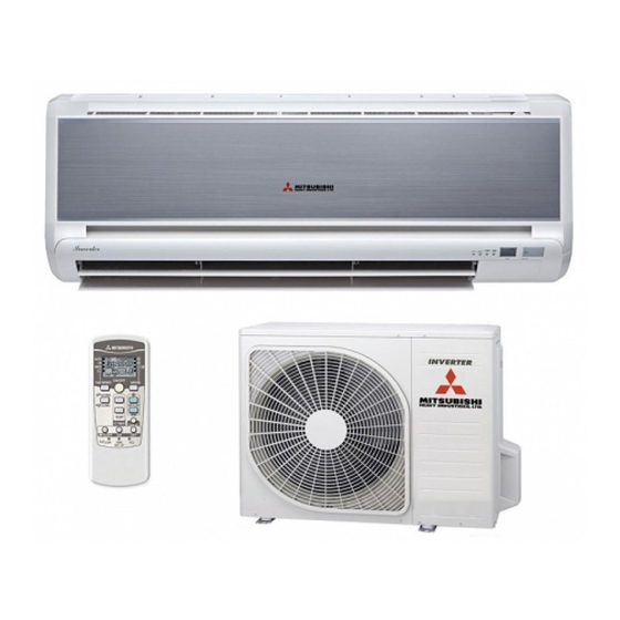
Mitsubishi Heavy Industries Air Conditioners
Technical Manual
Manual Number: 2011 No. W2-01
Variable Frequency Wall Mounted Type
Room Air Conditioners
(Split system, heat pump type)
SRK20MA-S/SRC20MA-S
SRK25MA-S/SRC25MA-S
SRK35MA-S/SRC35MA-S
SRK50MA-S/SRC50MA-S
(R410A Refrigerant Used)
MITSUBISHI HEAVY INDUSTRIES, LTD.
- 1 -
Advertisement
Table of Contents

Related Manuals for Mitsubishi Heavy Industries SRK20MA-S


Summary of Contents for Mitsubishi Heavy Industries SRK20MA-S
- Page 1 Mitsubishi Heavy Industries Air Conditioners Technical Manual Manual Number: 2011 No. W2-01 Variable Frequency Wall Mounted Type Room Air Conditioners (Split system, heat pump type) SRK20MA-S/SRC20MA-S SRK25MA-S/SRC25MA-S SRK35MA-S/SRC35MA-S SRK50MA-S/SRC50MA-S (R410A Refrigerant Used) MITSUBISHI HEAVY INDUSTRIES, LTD. - 1 -...
-
Page 2: Table Of Contents
Table of Contents 1. GENERAL INFORMATION…………..……………………….……1 1.1 Features……………………………………..……………………..…1 1.2 Model identification………………………………………………1 2 MODEL SELECTION…………………………………………………2 2.1 Model function..…………..…….……..………………………..……2 2.2 Range of usage……………………………………………..………6 2.3 Outline drawing……………………………..……………………..…6 2.4 Cooling cycle system diagram…….………………..…………...…8 2.5 Performance curve……………………………………………………9 3 ELECTRICAL WIRING DIAGRAM……………………………….10 4 NAME OF EACH PART AND ITS FUNCTION………….12 4.1 Name of each part…………………………..…………………..15 4.2 Emergency switch…………………………..…………………..15 4.3 Automatic restart……………..…………..………………………..15... -
Page 3: Mount Assembly
4.18 Outline of drying operation..........21 4.19 Outline of defrosting operation..........21 4.20 Outline of vertical and horizontal flaps control........23 4.21 Outline of electronic expansion valve (EEV) control.....24 4.22 Outline of compressor control.........24 4.23 Outline of outdoor fan control.........24 4.24 Outline of indoor fan control.........25 5 INSTALLATION................27 5.1 Selection of installation location..........2 9 5.2 Installation of indoor unit..............30... -
Page 4: General Information
1 GENERAL INFORMATION 1.1 Features (1) Inverter ● Heating/cooling The rotate speed of the compressor is changed steplessly in relation to varying load, and is linked with the fans of indoor and outdoor units controlled by the changes of frequency, thus controls the power. -
Page 5: Model Selection
2 MODEL SELECTION 2.1 Model function 2.1.1 Model: SRK20MA–S (Indoor unit) SRC20MA–S (Outdoor unit) Item Unit Indoor unit SRK20MA–S Outdoor unit SRC20MA–S Net weight 780×290×540 Machine 798×230×294 dimension Length× 920×380×590 Package 850×365×310 Width ×Height dimension Color White Ash-colored Through-flow type, AS resin + Axial flow type, AS resin + glass glass fiber fiber (embedded damping spindle... - Page 6 2.1.2 Model: SRK25MA–S (Indoor unit) SRC25MA–S (Outdoor unit) Item Unit Indoor unit SRK25MA–S Outdoor unit SRC25MA–S Net weight 780×290×540 Machine 798×230×294 dimension Length× 920×380×590 Package 850×365×310 Width ×Height dimension Color White Ash-colored Through-flow type, AS resin + Axial flow type, AS resin + glass glass fiber fiber (embedded damping spindle sleeve)
- Page 7 2.1.2 Model: SRK35MA–S (Indoor unit) SRC35MA–S (Outdoor unit) Item Unit Indoor unit SRK35MA–S Outdoor unit SRC35MA–S Net weight 10.5 780×290×540 Machine 798×230×294 dimension 920×380×590 Package Length× 850×365×310 Width ×Height dimension Color White Ash-colored Through-flow type, AS resin + Axial flow type, AS resin + glass glass fiber fiber (embedded damping spindle sleeve)
- Page 8 2.1.2 Model: SRK50MA–S (Indoor unit) SRC50MA–S (Outdoor unit) Item Unit Indoor unit SRK50MA–S Outdoor unit SRC50MA–S Net weight 10.5 Machine 798×230×294 850×290×640 dimension Length× Package 850×365×310 990×395×700 Width ×Height dimension Color White Ash-colored Through-flow type, AS resin + Axial flow type, AS resin + glass glass fiber fiber (embedded damping spindle sleeve)
-
Page 9: Range Of Usage
2.2 Range of usage Please use the air conditioners within the following range of usage, otherwise the protector will be triggered. Cooling Operation Heating Operation Outdoor temperature About 18℃~43℃ About -15~24℃ Indoor temperature About18℃~32℃ About below 30℃ Indoor humidity About below 80% 20~50 Models Max. - Page 10 - 7 -...
- Page 11 (2) Outdoor unit: SRC20MA-S/ SRC25MA-S/ SRC35MA-S Unit: mm Drainage pipes Junction box Operation valve (Liquid) Flare connecting Operation valve (Gas) Flare connecting (3) Outdoor unit: SRC50-MA-S Unit: mm Drain holes Terminal block Operation valve (Liquid) Flare connecting Operation valve (Gas) Flare connecting - 8 -...
-
Page 12: Cooling Cycle System Diagram
2.4 Cooling cycle system diagram Models: MA-S Series Indoor unit Outdoor unit Circulation of cooling Circulation of heating Operation valve (Gas) Flare connecting Outdoor air temp. sensor Gas pipe Note (1) model Refrigerant outlet pipe model Check joint Inlet air temp. sensor 4-way valve Gas liquid... -
Page 13: Performance Curve
2.5 Performance curve The cooling and heating capacities are measured in the following conditions. The actual capacity can be obtained with the following formula. Actual capacity = Rating capacity x Correction factor (1) Capacity correction according to indoor and outdoor temperatures: Cooling Heating Accommodation... - Page 14 Nominal cooling Temp. correction Piping length capacity factor correction factor 0.86 ≈ 3838W Actual heating capacity = 5800 0.81 0.95 Nominal heating Temp. correction Piping length Frosting capacity factor correction factor correction factor - 11 -...
-
Page 15: Electrical Wiring Diagram
3 ELECTRICAL WIRING DIAGRAM 3.1 Circuit diagram: 20, 25, 35MA-S - 12 -... - Page 16 3.2 Circuit diagram: 50MA-S - 13 -...
-
Page 17: Name Of Each Part And Its Function
4 NAME OF EACH PART AND ITS FUNCTION 4.1 Name of each part Indoor unit Air inlet panel Suctions air in the room Draws in the indoor air. Indication section of A/C and signal receiver of remote controller Wireless remote controller Air filter Removes dust or dirt from the inlet air filtere... - Page 18 Indication section of air conditioner RUN lamp (green) ON during running 1.5 sec. Running Heat-retaining Stop 0.5 sec. TIMER lamp (yellow) ON during timing operation HI POWER/JET lamp (green) ON during HI POWER/JET running POWER SAVE lamp (green) Receiving part of remote controller ON during Power Save running Receives signals from remote controller Temp.
-
Page 19: Operation And Indication Section For Remote Control
Operation and indication section for remote control Operation section FAN SPEED button MODE button Each time this button is pressed, ■ Each time this button is pressed, ■ displaying changes in order. displaying changes in order. HI POWER button ON/OFF (luminous) button Press this button to begin running;... -
Page 20: Emergency Switch
4.2 Emergency switch: (1) When the remote controller is not used, the emergency operation switch “ON/OFF” button can be used to turn on/off the machine. (2) Press the “ON/OFF” button to begin operation. Press it again to stop. (3) Operation items: ●... -
Page 21: Sleep Operation
4.6 SLEEP operation: (1) SLEEP operation: This function prevents the temperature in the cooling operation from becoming too low and the temperature in the heating operation from becoming too high; regulates the room temperature automatically as time goes by; and stops automatically after the time set. Sleep (2) Operation method: timing... -
Page 22: Timing On
4.8 Timing ON: (1) Timing ON: The air conditioner begins to detect the room temperature 60 minutes before the set time and commences operation 5-60 minutes in advance according to the difference between the room temperature and the set temperature to make the room temperature reach the best value at the set time. -
Page 23: Current Time Setting
4.10 Current time setting: (1) After inserting the batteries, the current time is set to 13:00 automatically. In time setting, all contents displayed on the remote controller are reset. ON/OFF (2) Operation method: For example, to set to 11:30, ① Step 1: Use the pen point to press the ACL switch and the TIMER lamp will flash. -
Page 24: Power Save Operation
4.13 POWER SAVE operation: (1) The Power Save function regulates the frequency of the compressor, etc. and reduces the current value during operation, thus reduces the cooling/heating capacity to save energy. (2) Operation method: Point the remote controller at the air conditioner and use the Power pen point to press the POWER SAVE button to make point at Power Save... -
Page 25: Area Setting
4.15 Area setting: (1) The area setting function is used to regulate the indoor air and the air in the specific area in the room. (2) Operation method: When the air conditioner is running, press the AREA button, as needed, to switch to the desired area. (3) The area indications are as follows: Area Area... -
Page 26: Outline Of Drying Operation
(3) If the air conditioner is started again within 1 hour after the automatic operation stops, or it is converted to automatic operation in the heating, cooling or drying mode, it will operate in the previous mode. (4) The temperature can be set in the following range. The relationship between the signals of the wireless remote controller and the set temperature is as follows: Signals of wireless remote controller (displaying) Cooling... - Page 27 ② The outdoor heat exchanger sensor (Th0-R) meets one of the following conditions: A) When the actual rotate speed of the compressor N ≥ 62 rps: Th0-R ≤ -5℃; B) When the actual rotate speed of the compressor N < 62 rps: Th0-R ≤ -4℃; ③...
-
Page 28: Outline Of Vertical And Horizontal Flaps Control
4.20 Outline of vertical and horizontal flaps control: (1) Overview: Sm1: Vertical flap (mounted on the right side when you face the appliance); Sm2: Left horizontal flap (mounted on the left side when you face the appliance); Sm3: Right horizontal flap (mounted on the right side when you face the appliance); (2) Vertical flap Sm1: The level set is 0℃. -
Page 29: Outline Of Electronic Expansion Valve (Eev) Control
4.21 Outline of electronic expansion valve (EEV) control: (1) Overview: ① Initial control: When the power is ON and the reference position is determined, the EEV opening is widened within 5 minutes to let the refrigerant return, thus makes the low pressure rise easily and avoid misdiagnosis of insufficient refrigerant and poor EEV operation as the low pressure can’t rise after decline;... -
Page 30: Outline Of Indoor Fan Control
(2) Priority of rotate speed control: Error response control > Outdoor fan control in compressor soft start control > Outdoor fan control in defrosting control > Outdoor fan control/indoor forcing outdoor fan running control in stop mode > Outdoor fan control at start > Outdoor fan control at the low outdoor temperature in cooling >... - Page 31 (7) The relationship between the rotate speed of heat-retaining during heating and the temperature measured by the indoor heat exchanger sensor Th1-R1 is as follows: Temperature measured by the indoor heat exchanger sensor When the compressor displays OFF When the compressor displays ON - 28 -...
-
Page 32: Installation
5 Installation Precautions for installation ○ Use this system only for household and residence. ○ This appliance must be installed according to the national wiring regulation. ○ A 2-level switch must be used for the fixed wiring of the power supply and its disconnection clearance must be at least 3mm. - Page 33 WARNING • To recover refrigerant, stop the compressor before closing the valve and disconnecting the refrigerant piping. If the refrigerant piping is disconnected before the compressor stops and when the service valve is opened, it can cause frostbite or injury due to rapid refrigerant leakage, and burst or personal injury due to anomalously high pressure in the refrigerant circuit into which air is sucked •...
-
Page 34: Selection Of Installation Location
CAUTION • Do not install the outdoor unit in the locations listed • Do not install the outdoor unit in a location where below. insects and small animals can inhabit. • Locations where discharged hot air or operating sound of Insects and small animals can enter the electric parts and the outdoor unit can bother neighborhood. -
Page 35: Installation Of Indoor Unit
Selection of installation location ○ The appliance must be installed at a location with the vents and air intake being 10cm away from walls. (In case the fence is 1.2m or above in height, or is overhead, the sufficient space between the unit and wall shall be secured.) ○... -
Page 36: Installation Of Indoor Unit
Installation of indoor unit Drilling holes and ing sleeve (optional) secur Drilling a hole with Φ65 whole core drill Adjusting the length of the sleeve Outdoor Indoor Thickness of wall ○ If the rear pipe is pulled out, cut the Use the whole core drill to drill a hole. - Page 37 ● Precautions for connection to the left and to Mounting pipe support center/rear [Top view] Pipe shaping Connecting the pipe to the left Connecting the pipe to the right The pipe can be connected to Connecting the pipe to the the rear, left, left rear, bottom Connecting the pipe to the left Pipe...
-
Page 38: Installation Of Outdoor Unit
Drainage pipe After all mounting steps, check ○ Mount the drainage pipe at a downward angle. Caution whether the drain is proper. ○ Avoid the following drainage pipe connections. Otherwise, water leakage may occur. Odor from sink End of drainage pipe Higher than as required Undulating End of drainage... -
Page 39: Air Purging
Measurement B Copper pipe Flaring Conventional (R22) flare tool Clutch type flare tool Model diameter Clutch type for R410A Wing nut type Measurement B Use a flare tool designed for R410A or a conventional flare tool. Please note that measurement B (protrusion from the flaring block) will vary depending on the type of flare tool in use. -
Page 40: Precautions For Wireless Remote Controller Operation
Moving or removing the appliance ○ In order to meet the requirement of environmental protection, pump down (recovering refrigerant) is required. ○ The effect of pump down is to return the refrigerant from the indoor unit to the outdoor unit when the pipes are removed from the main frame. -
Page 41: Standard Running Data
5.6 Standard running data: SRK20MA-S SRK25MA-S SRK35MA-S SRK50MA-S High pressure (MPa) Cooling Heating 2.2~2.9 2.2~2.9 2.0~3.2 2.4~3.6 Low pressure (MPa) Cooling 1.0~1.2 1.0~1.2 0.9~1.2 0.8~1.2 Heating Temp. difference Cooling 9~10 9~11 8~14 10~16 between inlet and Heating 9~15 9~16 10~21... -
Page 42: Maintenance
6. MAINTENANCE 6.1 Electrical parts failure diagnosis method (1) Precautions: ① Be sure to switch off the power before disassembling and checking the air conditioner. Maintenance of the indoor unit should commence 1 minute after the power is switched off. With respect to maintenance of the outdoor unit, the major circuit (electrolytic capacitor), which may be charged, should be fully discharged before the maintenance. - Page 43 Procedure of diagnosis (when the air * Correct voltage refers to the voltage between 198-242V. conditioner does not run at all) Has the cable been Check that the cable is inserted inserted into the power into the correct power supply. supply with correct Check the operation situation.
- Page 44 (4) Procedure of failure diagnosis (when the air conditioner can run) Note: (1) When only stop data is indicated, the air conditioner is normal. However, when the same protection is triggered repeatedly (more than 3 times), which becomes the user’s complaint, it should be judged according to the content of failure.
- Page 45 (5) Indication of self-diagnosis When the air conditioner stops abnormally, the cause is indicated with lamps. Three minutes after abnormal stop, use the remote controller to start the appliance. The error indication will disappear and the appliance will commence operation Note: (2) It can’t be restarted with the remote controller 3 minutes after abnormal stop.
- Page 46 (6) Service mode (failure mode reading function) The air conditioner records the past error indication and protection stops (service data). If the indication of self-diagnosis can’t be confirmed, it can be confirmed through service data to grasp the condition when the error occurs. (a) Terms Term Description...
- Page 47 *3: Counting of flashing in service mode: 1.5 sec. light-up (beginning signal) and number of continuous flashes (Number of continuous flashes excluding the 1.5 sec. light-up (beginning signal)). ● Safe current (heating safety I) (for example, the stop code is “32”) RUN lamp (tens place) flashes 3 times and TIMER lamp (ones place) flashes 2 times: 3 x 10 + 2 x 1 = 32.
-
Page 48: Temperature Setting
② Stop data Settings of remote controller Indication data Operation Air flow Temperature switching switching setting Cooling 21℃ Indicates the cause of the last stop due to protection control, etc. (stop code) 22℃ Indicates the cause of second to last stop due to protection control, etc. - Page 49 Flash 7 Heating safe Excessive refrigerant Safe current stops in the safe current times current III III+3A mode during heating operation. Compressor lock - 46 -...
- Page 50 No. of flashes in Stop Content of Cause Conditions Error Automatic service mode code or failure indication restoration error TIMER Category Class code lamp lamp (ones (tens place) place) Flash 1 Safe current Cooling Excessive refrigerant Stops in the overload 1 mode during Flash 4 time overload 1...
- Page 51 Notes: (1) The number of flashes in service mode excludes the 1.5 sec. light-up (beginning signal). (See the following example.) ● Safe current (heating safety I) (for example, the stop code is “32”) RUN lamp (tens place) flashes 3 times and TIMER lamp (ones place) flashes 2 times: 3 x 10 + 2 x 1 = 32.
- Page 52 (e) List of temperatures measured by room temperature sensor, indoor heat exchanger sensor, outdoor air temp. sensor, and outdoor heat exchanger liquid pipe sensor Unit: ℃ TIMER lamp (ones place) RUN lamp (tens place) Does the buzzer sound? (Sound means negative) (Sounds for 0.1 sec.) (Not sound)
- Page 53 0.1 sec. When the temperature is < 0, the buzzer will sound. Sound of When the temperature is ≥ 0, the buzzer will not sound. buzzer (Negative) 1.5 sec. RUN lamp (tens place) 0.5 sec. 0.5 sec. TIMER lamp (ones place) 11 sec.
- Page 54 (f) List of temperatures of compressor vent-pipe Unit: ℃ TIMER lamp (ones place) RUN lamp (tens place) Does the buzzer sound? (Sound means negative) (Sounds for 0.1 sec.) (Not sound) * If there is no data recorded (the error code is normal), the information of each sensor is as showed in the table below: Value displayed by the sensor when the error code is Name of sensor...
- Page 55 Check data recording sheet Customer Model Date Equipment name Complaint Settings of remote controller Content of indication data Indication result Content of indication Temp. Operation Air flow Buzzer RUN lamp TIMER setting switching switching (yes/no) (no. of lamp (no. of times) times) Code of last error...
- Page 56 (7) Check method according to the content of failure Error of sensor (Wire break of sensor and poor joint contacting) Is the joint contacting normal? Correct the plug/socket (replace the joint) Is the resistance value of the sensor Replace the sensor. normal? Replace the PCB.
- Page 57 Error of outdoor unit (Damage of power transistor, wiring break of compressor) Has all three-phase output voltage Failure of inverter been applied to the power transistor? Has the wiring for the compressor Connect it properly. been properly connected? Check the compressor. Compressor over heat (Insufficient refrigerant, failure of discharge pipe sensor) Is the resistance value of the...
-
Page 58: Compressor Lock
Serial signal transmission error (Wrong power supply and signal cable connection, failure of indoor and outdoor PCB, error of power supply system) Is the power supply abnormal in Failure caused by one-time reason (noise, operation after reset? etc.), not failure of machine Is the indoor and outdoor Correct the indoor and outdoor connection connection correct? - Page 59 Outdoor fan motor error (Failure of fan motor, failure of outdoor PCB) Is the connection of the connector Correct the connector. normal? Has voltage been applied to the fan Failure of outdoor PCB motor? Failure of fan motor (8) Actions in case of short circuit and wire break of sensor (a) Indoor unit Actions Sensor...
- Page 60 (9) Check method for indoor electrical components Is the fuse (3.15A) intact? Replace the fuse. Has voltage been applied to Replace the PCB. between terminal block 1~2 (AC220/230/240V)? Dose the voltage between terminal Replace the PCB. block 2~3 fluctuate between DC 0~12V? Notes: (1) Communication is sent only when 52C is ON, so please check the operation status.
- Page 61 (11) Remote controller failure diagnosis procedure Note (1) Is the remote ●Low battery of remote controller controller ● Defective remote controller Replace normal after reset? Restart Note (1) Does the air (a) Press the ACL switch on the remote controller. No error conditioner (b) If the set temperature displayed is 0℃...
- Page 62 (12) Check method for outdoor unit 1) Circuit diagram of 20, 25 and 35MA-S outdoor units - 59 -...
- Page 63 2) Circuit diagram of 50MA-S outdoor unit - 60 -...
- Page 64 (13) Check method for outdoor circuit board (inverter) Make confirmation after checking that the indoor circuit board is normal. (I) Use a multimeter to conduct inspection. a) Unplug the plug. b) Remove the output cables U, V and W (to the compressor) of the power transistor. (Note: The inspection of inverter can be conducted only after the capacitor is discharged and after making sure the residual voltage is below 10V.) c) Insert the plug and press and hold the back-up switch for over 5 sec.
- Page 65 (14) Check method for EEV After the power is switched on, check the opening of the EEV and the sound and voltage within 10 sec. of operation. [In operation, only the opening is changed and the voltage can’t be measured.] 1) If sound of the EEV is heard, it indicates the EEV is basically good.
-
Page 66: Servicing
6.2 Servicing (1) Evacuation Evacuation refers to the process of purging non-condensable gas, air, water, etc. from the refrigerant equipment with a vacuum pump. The R410A refrigerant is highly water insoluble, therefore even a little water left in the refrigerant equipment will be frozen, which causes the so-called water blockage. - Page 67 7 Service Manual for Air Conditioners with Refrigerant Piping Mounted/Using R410A Refrigerant (The following is selected from the document published by The Japanese Refrigeration and Conditioning Industry Association) 7.1 Overview 7.1.1 R410A Refrigerant (1) Using R410A in air conditioners In 1974, scientists found that the ozone in the upper stratosphere (about 20-40 km away from the ground) may be damaged by ozone depleting substances such as CFC (chlorofluorocarbon) and HCFC (hydrochlorofluorocarbon), etc.
- Page 68 (3) Lubricants for R410A Mineral oil, AB (Alkybenzene), etc. are widely used as the lubricants for R22. R410A is not easily dissolved in conventional lubricants such as mineral oil, etc. and such lubricants likely stay in refrigerant cycle, so ester, ether and other synoil in which R410A is highly dissoluble are generally used.
- Page 69 (2) Joints Copper pipes use flared joints or sleeve joints. Be sure to clean them before use. a) Flared joints Flared joints are used to connect copper pipes that can’t be used for piping as their outside diameter exceeds 20mm. In such case, sleeve joints may also be used. The sizes of ends of flared pipes, ends of flared joints and flare nuts are shown in Tables 5~8 (see pages 112 and 113).
- Page 70 d) Flaring Ensure to clean the clamps and copper pipes. Use the clamping bars to conduct flaring correctly. Use the flare tools for R410A or conventional flare tools. The size of flaring varies depending on the kinds of flare tool. Please note that the size must be adjusted to “Size A”...
- Page 71 Table 8 Sizes of R22 flaring and flare nut [Unit: mm] Rating Outside Size Thickness Width of flare nut diameter diameter (2) Flaring procedure and precautions a) Ensure there is not any defect or dust, etc. on the flaring and connection. b) Correctly connect the flared surface and the joint axis.
- Page 72 (2) Characteristics a) Pipe sleeve Copper pipes as R410A pipe sleeves must have a thickness as shown in Table 3 (see Page 59) and Tables 5 and 6 (see Page 61), and sizes of flaring and flare nuts different from those of R22. Therefore, be sure to select pipe sleeves suitable for R410A.
- Page 73 (3) Welding flux a) Reasons for using welding flux ● To remove the oxide film and impurity from metal surface to help the flow of brazing filler. ● To prevent oxidization on metal surface in welding. ● To reduce the surface tension of brazing filler to make it better adhere to the treated metal. b) Features of welding flux required ●...
- Page 74 Reducing valve Flowmeter Disconnecting valve From nitrogen cylinder Piping Nitrogen Rubber stopper for sealing Figure 5 Preventing oxidation in welding * Precautions for welding ① General precautions 1) The weld strength should meet the requirement. 2) Keep air tightness under the pressure condition after the operation. 3) During welding, avoid damaging the components due to high temperature.
- Page 75 designed specifically for (1) Tools R410A a) Manifold pressure gauge ● As R410A has the property of high pressure, conventional tools can’t be used. Table 11 Difference between conventional high/low pressure gauge and pressure gauge for R410A Conventional pressure gauge Pressure gauge designed specifically for R410A High pressure gauge (Red)
- Page 76 e) Flare tool (clutch type) ● The flare tool for R410A has a big clamping bar receiving hole, so as to set the copper pipe portion protruding from the clamping bar during flaring to 0~0.5mm and have stronger elasticity for the increased torque of EEV. This type of flare tool can also be used for R22 copper pipes. f) Adjusting the scaled rule for the protruding portion (used when a conventional flare tool (including clutch type) is used for flaring) ●...
- Page 77 7.3.2 New installation (when new refrigerant piping is used) (1) Use the vacuum pump to suction air and detect any gas leakage (see Figure 6) a) Connect the charge hose to the outdoor unit. ① b) Connect the charge hose to the vacuum pump adapter. ② Here, fully close the control valves.
- Page 78 f) After charging the liquid refrigerant into the air conditioner by closing the charging valve, fully close Valve Lo of the manifold pressure gauge to stop. ②⑤ g) Quickly move the charge hose away from the service opening.⑥ If the movement is slow, the circulating refrigerant may be leaked. h) Secure the covers of the service opening and control valve, and check for any gas leakage around the covers.
- Page 79 7.3.6 Recharging refrigerant in servicing If it is necessary to charge refrigerant, charge the specified amount of refrigerant by following these steps. (For details, see the operation manual prepared by the equipment manufacturer.) 1) Connect the charge hose to the service opening of the outdoor unit. 2) Connect the charge hose to the vacuum pump adapter.
- Page 80 (4) Recovery procedure a) According to the instructions on refrigerant recovery device (see the operation manual supplied), operate the device to recover refrigerant. b) Pay attention to the following during the operation. ① Confirm that the refrigerant recovery device runs according to the requirements and the operation status is always monitored, so as to take correct actions in case of emergency.
- Page 81 b) Charge hose (pressure resistant fluorocarbon hose) and sealing ring ● Thickness 1/48, multiple lengths available ● Hose with the pressure resistance property higher than 5.2MPa (52kg/cm ● In general, only one end has fixture. Hose (4) Manifold pressure gauge Fixture sealing ring ●...
-
Page 82: Mount Assembly
MOUNT ASSEMBLY 8.1 Indoor unit 8.1.1 SRK20MA-S SRK20MA-S-PANEL&FAN ASSY Parts No Parts Name RE.Q RYD102A033H PANEL ASSY,FRONT RYD122A057C PANEL,FRONT RYD435A056G GRILLE,AIR INLET RYD437A030 FILTER,AIR RYD129A088A RYD133A049 PLATE ASSY,ORNAMENT RYD129A047 HOLDER,FILTER RYD011F037 LABEL,MODEL NAME 8-26 RYD435A054A GRILLE ASSY,AIR OUT RYD435A055 GRILLE,AIR OUTLET... - Page 83 RYD935C005 COLLAR RYD129A098 BRACKET,MOTOR(L) RYD129A099 BRACKET,MOTOR(R) RYD144A018 CRANK(C) RYD512T002J MOTOR,STEPPING RYD512T002K MOTOR,STEPPING 21-22 RYD129A100 BOX ASSY,GEAR RYD512T019B MOTOR,STEPPING RYD504A028 HARNESS ASSY RYD423A009 HOSE,DRAIN SSA326A047 PLUG RYD111A017A BASE ASSY RYD129A084 CASE,MOTOR(U) RYD129A085 CASE,MOTOR(L) RYG923C001 BEARING,PLANE RYD431G002 IMPELLER RYD512T022A MOTOR,DC RYD032A007A PLATE,INSTALLATION RYD129A103A COVER(PIPE) RYD913A003...
- Page 84 - 81 -...
- Page 85 SRK20MA-S-HEAT EXCH.&CONTROL Parts No Parts Name RE.Q RYD301A057B HEAT EXCH ASSY(AIR) RYD129A093 BRACKET(L) RYD315D031 HEADER ASSY RYD321A139 PIPE RYD321A140C PIPE ASSY RYG323F002 UNION,SOLDER RYG323F002A UNION,SOLDER RYD129A089 PLATE,BAFFLE 9-20 RYD501A073H CONTROL ASSY, UNIT 9-10 RYD142A083 BOX ASSY,CONTROL(R) RYD142A081 BOX,CONTROL(R) RYD132A006 COVER,CONTROL(R)
- Page 86 18-20 RYD505A048F PWB ASSY RYG555B002A VARISTOR RYG564A003 FUSE(CURRENT) RYD503A016 DISPLAY ASSY RYD505A016 PWB ASSY(DISPLAY) 23-24 RYD132A010 LID ASSY,CONTROL RYD132A009 LID,CONTROL RYD132A008 COVER,LID RYA941F001 SPRING,LEAF RYD129A104 COVER ASSY(TB) RYD008A046B PARTS SET RYD437A004A FILTER ASSY,CLEAN(PP,HEPA) RYD437A010A FILTER ASSY,CLEAN(PP,HEPA) RYD012A193 MANUAL,INSTRUCTION&INS RLA502A001D CONTROL ASSY,REMOTE SSA554D183 KILLER,NOISE RYD566A092...
- Page 87 - 84 -...
- Page 88 8.1.2 SRK25MA-S SRK25MA-S-PANEL&FAN ASSY Parts No Parts Name RE.Q RYD102A033H PANEL ASSY,FRONT RYD122A057C PANEL,FRONT RYD435A056G GRILLE,AIR INLET RYD437A030 FILTER,AIR RYD129A088A RYD133A049 PLATE ASSY,ORNAMENT RYD129A047 HOLDER,FILTER RYD011F037A LABEL,MODEL NAME 8-26 RYD435A054A GRILLE ASSY,AIR OUT RYD435A055 GRILLE,AIR OUTLET RYD436A033A FLAP(A) RYD436A034A FLAP(B) 11-12 RYD436A035 LOUVER ASSY(R)
- Page 89 RYD129A098 BRACKET,MOTOR(L) RYD129A099 BRACKET,MOTOR(R) RYD144A018 CRANK(C) RYD512T002J MOTOR,STEPPING RYD512T002K MOTOR,STEPPING 21-22 RYD129A100 BOX ASSY,GEAR RYD512T019B MOTOR,STEPPING RYD504A028 HARNESS ASSY RYD423A009 HOSE,DRAIN SSA326A047 PLUG RYD111A017A BASE ASSY RYD129A084 CASE,MOTOR(U) RYD129A085 CASE,MOTOR(L) RYG923C001 BEARING,PLANE RYD431G002 IMPELLER RYD512T022A MOTOR,DC RYD032A007A PLATE,INSTALLATION RYD129A103A COVER(PIPE) RYD913A003 SCREW,TAP RYD132A011A...
- Page 90 - 87 -...
- Page 91 SRK25MA-S-HEAT EXCH.&CONTROL Parts No Parts Name RE.Q RYD301A057B HEAT EXCH ASSY(AIR) RYD129A093 BRACKET(L) RYD315D031 HEADER ASSY RYD321A139 PIPE RYD321A140C PIPE ASSY RYG323F002 UNION,SOLDER RYG323F002A UNION,SOLDER RYD129A089 PLATE,BAFFLE 9-20 RYD501A073J CONTROL ASSY, UNIT 9-10 RYD142A083 BOX ASSY,CONTROL(R) RYD142A081 BOX,CONTROL(R) RYD132A006 COVER,CONTROL(R) 11-12 RYD142A082 BOX ASSY,CONTROL(L)
- Page 92 18-20 RYD505A048G PWB ASSY RYG555B002A VARISTOR RYG564A003 FUSE(CURRENT) RYD503A016 DISPLAY ASSY RYD505A016 PWB ASSY(DISPLAY) 23-24 RYD132A010 LID ASSY,CONTROL RYD132A009 LID,CONTROL RYD132A008 COVER,LID RYA941F001 SPRING,LEAF RYD129A104 COVER ASSY(TB) RYD008A046B PARTS SET RYD437A004A FILTER ASSY,CLEAN(PP,HEPA) RYD437A010A FILTER ASSY,CLEAN(PP,HEPA) RYD012A193 MANUAL,INSTRUCTION&INS RLA502A001D CONTROL ASSY,REMOTE SSA554D183 KILLER,NOISE RYD566A092...
- Page 93 - 90 -...
- Page 94 8.1.3 SRK35MA-S SRK35MA-S-PANEL&FAN ASSY Parts No Parts Name RE.Q RYD102A033H PANEL ASSY,FRONT RYD122A057C PANEL,FRONT RYD435A056G GRILLE,AIR INLET RYD437A030 FILTER,AIR RYD129A088A RYD133A049 PLATE ASSY,ORNAMENT RYD129A047 HOLDER,FILTER RYD011F037B LABEL,MODEL NAME 8-26 RYD435A054A GRILLE ASSY,AIR OUT RYD435A055 GRILLE,AIR OUTLET RYD436A033A FLAP(A) RYD436A034A FLAP(B) 11-12 RYD436A035 LOUVER ASSY(R)
- Page 95 RYD129A098 BRACKET,MOTOR(L) RYD129A099 BRACKET,MOTOR(R) RYD144A018 CRANK(C) RYD512T002J MOTOR,STEPPING RYD512T002K MOTOR,STEPPING 21-22 RYD129A100 BOX ASSY,GEAR RYD512T019B MOTOR,STEPPING RYD504A028 HARNESS ASSY RYD423A009 HOSE,DRAIN SSA326A047 PLUG RYD111A017A BASE ASSY RYD129A084 CASE,MOTOR(U) RYD129A085 CASE,MOTOR(L) RYG923C001 BEARING,PLANE RYD431G002 IMPELLER RYD512T022A MOTOR,DC RYD032A007A PLATE,INSTALLATION RYD129A103A COVER(PIPE) RYD913A003 SCREW,TAP RYD132A011A...
- Page 96 - 93 -...
- Page 97 SRK35MA-S-HEAT EXCH.&CONTROL Parts No Parts Name RE.Q RYD301A059F HEAT EXCH ASSY(AIR) RYD129A093 BRACKET(L) RYD315D033 HEADER ASSY RYD321A152 PIPE RYD321A140C PIPE ASSY RYG323F002 UNION,SOLDER RYG323F002A UNION,SOLDER RYD129A089 PLATE,BAFFLE 9-20 RYD501A073K CONTROL ASSY, UNIT 9-10 RYD142A083 BOX ASSY,CONTROL(R) RYD142A081 BOX,CONTROL(R) RYD132A006 COVER,CONTROL(R) 11-12 RYD142A082 BOX ASSY,CONTROL(L)
- Page 98 18-20 RYD505A048H PWB ASSY RYG555B002A VARISTOR RYG564A003 FUSE(CURRENT) RYD503A016 DISPLAY ASSY RYD505A016 PWB ASSY(DISPLAY) 23-24 RYD132A010 LID ASSY,CONTROL RYD132A009 LID,CONTROL RYD132A008 COVER,LID RYA941F001 SPRING,LEAF RYD129A104 COVER ASSY(TB) RYD008A046B PARTS SET RYD437A004A FILTER ASSY,CLEAN(PP,HEPA) RYD437A010A FILTER ASSY,CLEAN(PP,HEPA) RYD012A193 MANUAL,INSTRUCTION&INS RLA502A001D CONTROL ASSY,REMOTE SSA554D183 KILLER,NOISE RYD566A092...
- Page 99 - 96 -...
- Page 100 8.1.4 SRK50MA-S SRK50MA-S-PANEL&FAN ASSY Parts No Parts Name RE.Q RYD102A033H PANEL ASSY,FRONT RYD122A057C PANEL,FRONT RYD435A056G GRILLE,AIR INLET RYD437A030 FILTER,AIR RYD129A088A RYD133A049 PLATE ASSY,ORNAMENT RYD129A047 HOLDER,FILTER RYD011F037C LABEL,MODEL NAME 8-26 RYD435A054A GRILLE ASSY,AIR OUT RYD435A055 GRILLE,AIR OUTLET RYD436A033A FLAP(A) RYD436A034A FLAP(B) 11-12 RYD436A035 LOUVER ASSY(R)
- Page 101 RYD129A098 BRACKET,MOTOR(L) RYD129A099 BRACKET,MOTOR(R) RYD144A018 CRANK(C) RYD512T002J MOTOR,STEPPING RYD512T002K MOTOR,STEPPING 21-22 RYD129A100 BOX ASSY,GEAR RYD512T019B MOTOR,STEPPING RYD504A028 HARNESS ASSY RYD423A009 HOSE,DRAIN SSA326A047 PLUG RYD111A017A BASE ASSY RYD129A084 CASE,MOTOR(U) RYD129A085 CASE,MOTOR(L) RYG923C001 BEARING,PLANE RYD431G002 IMPELLER RYD512T022A MOTOR,DC RYD032A007A PLATE,INSTALLATION RYD129A103A COVER(PIPE) RYD913A003 SCREW,TAP RYD132A011A...
- Page 102 - 99 -...
- Page 103 SRK50MA-S-HEAT EXCH.&CONTROL Parts No Parts Name RE.Q RYD301A059B HEAT EXCH ASSY(AIR) RYD129A093 BRACKET(L) RYD315D033 HEADER ASSY RYD321A152 PIPE RYD321A140B PIPE ASSY RYG323F002A UNION,SOLDER RYG323F002B UNION,SOLDER RYD129A089 PLATE,BAFFLE 9-20 RYD501A073L CONTROL ASSY, UNIT 9-10 RYD142A083 BOX ASSY,CONTROL(R) RYD142A081 BOX,CONTROL(R) RYD132A006 COVER,CONTROL(R) 11-12 RYD142A082 BOX ASSY,CONTROL(L)
- Page 104 18-20 RYD505A048J PWB ASSY RYG555B002A VARISTOR RYD564A002 FUSE(CURRENT) RYD503A016 DISPLAY ASSY RYD505A016 PWB ASSY(DISPLAY) 23-24 RYD132A010 LID ASSY,CONTROL RYD132A009 LID,CONTROL RYD132A008 COVER,LID RYA941F001 SPRING,LEAF RYD129A104 COVER ASSY(TB) RYD008A046B PARTS SET RYD437A004A FILTER ASSY,CLEAN(PP,HEPA) RYD437A010A FILTER ASSY,CLEAN(PP,HEPA) RYD012A193 MANUAL,INSTRUCTION&INS RLA502A001D CONTROL ASSY,REMOTE SSA554D183 KILLER,NOISE RYD566A092A...
- Page 105 - 102 -...
-
Page 106: Outdoor Unit
8.2 Outdoor unit 8.2.1 SRC20MA-S SRC20MA-S-PANEL&FAN ASSY Parts No Parts Name RE.Q RYF122A002 PANEL ASSY,FRONT RYF124A001A PANEL,TOP RYF123A002 PANEL,SIDE(R) RYF435A003A GRILL ASSY,AIR OUT RYF132A002 PANEL ASSY,SERVICE RYF944B001 HANDLE RYF142A013 COVER(TB) RYF913A002 SCREW,TAP RYF913A002A SCREW,TAP W010D04X008 TAP-SCREW,CRS-TRS 1 W010D04X012 TAP-SCREW,CRS-TRS 1 RYF129A006 PLATE RYF937A002A... - Page 107 RYF141A005 PLATE ,BAFFLE RYF111A003F BASE ASSY - 104 -...
- Page 108 SRC20MA-S-HEAT EXCH&CONTROL Parts No Parts Name RE.Q RYF301A042 HEAT EXCH ASSY(AIR) RYF304A156G PIPING ASSY(4WAY) RYF325A005 PIPE,SHELL RYC325A001 PIPE,SHELL RYF382C010 VALVE,S(4WAY) RYF116A008 BRACKET,VALVE RYF381A070 VALVE,SERVICE(1/4") RYF381A069 VALVE,SERVICE(3/8") 8-10 RYF304A109A PIPING ASSY(EXPAN) SSA387F051 VALVE,BODY(EXP) RYF315B048 CAPILLARY RYG357A003 STRAINER RYF154D010 INSULATION,COMP RYF154D009 INSULATION,COMP RYF154D013 INSULATION,COMP RYF154D037...
- Page 109 RYF011F037B LABEL,MODEL NAME RYF011H029 LIST,LABEL(ENERGY) RYC008A002 PARTS,STANDARD - 106 -...
- Page 110 8.2.2 SRC25MA-S SRC25MA-S-PANEL&FAN ASSY Parts No Parts Name RE.Q RYF122A002 PANEL ASSY,FRONT RYF124A001A PANEL,TOP RYF123A002 PANEL,SIDE(R) RYF435A003A GRILL ASSY,AIR OUT RYF132A002 PANEL ASSY,SERVICE RYF944B001 HANDLE RYF142A013 COVER(TB) RYF913A002 SCREW,TAP RYF913A002A SCREW,TAP W010D04X008 TAP-SCREW,CRS-TRS 1 W010D04X012 TAP-SCREW,CRS-TRS 1 RYF129A006 PLATE RYF937A002A CLAMP,WIRE 14-18 RYF401A011G...
- Page 111 RYF111A003F BASE ASSY - 108 -...
- Page 112 SRC25MA-S-HEAT EXCH&CONTROL Parts No Parts Name RE.Q RYF301A042 HEAT EXCH ASSY(AIR) RYF304A156G PIPING ASSY(4WAY) RYF325A005 PIPE,SHELL RYC325A001 PIPE,SHELL RYF382C010 VALVE,S(4WAY) RYF116A008 BRACKET,VALVE RYF381A070 VALVE,SERVICE(1/4") RYF381A069 VALVE,SERVICE(3/8") 8-10 RYF304A109A PIPING ASSY(EXPAN) SSA387F051 VALVE,BODY(EXP) RYF315B048 CAPILLARY RYG357A003 STRAINER RYF154D010 INSULATION,COMP RYF154D009 INSULATION,COMP RYF154D013 INSULATION,COMP RYF154D037...
- Page 113 RYF129A003 HOLDER,SENSOR RYF142A011 (40) RYF011F037B LABEL,MODEL NAME (41) RYF011H029A LIST,LABEL(ENERGY) (42) RYC008A002 PARTS,STANDARD - 110 -...
- Page 114 8.2.3 SRC35MA-S SRC35MA-S-PANEL&FAN ASSY Parts No Parts Name RE.Q RYF122A002 PANEL ASSY,FRONT RYF124A001A PANEL,TOP RYF123A002 PANEL,SIDE(R) RYF435A003A GRILL ASSY,AIR OUT RYF132A002 PANEL ASSY,SERVICE RYF944B001 HANDLE RYF142A013 COVER(TB) RYF913A002 SCREW,TAP RYF913A002A SCREW,TAP W010D04X008 TAP-SCREW,CRS-TRS 1 W010D04X012 TAP-SCREW,CRS-TRS 1 RYF129A006 PLATE RYF937A002A CLAMP,WIRE 14-18 RYF401A011G...
- Page 115 RYF111A003F BASE ASSY - 112 -...
- Page 116 SRC35MA-S-HEAT EXCH&CONTROL Parts No Parts Name RE.Q RYF301A027 HEAT EXCH ASSY(AIR) RYF304A156C PIPING ASSY(4WAY) RYF325A005 PIPE,SHELL RYC325A001 PIPE,SHELL RYF382C010 VALVE,S(4WAY) RYF116A008 BRACKET,VALVE RYF381A070 VALVE,SERVICE(1/4") RYF381A069 VALVE,SERVICE(3/8") 8-10 RYF304A109A PIPING ASSY(EXPAN) SSA387F051 VALVE,BODY(EXP) RYF315B048 CAPILLARY RYG357A003 STRAINER RYF154D010 INSULATION,COMP RYF154D009 INSULATION,COMP RYF154D013 INSULATION,COMP RYF154D037...
- Page 117 (40) RYF011F037B LABEL,MODEL NAME (41) RYF011H029B LIST,LABEL(ENERGY) (42) RYC008A002 PARTS,STANDARD - 114 -...
- Page 118 8.2.4 SRC50MA-S SRC50MA-S-PANEL&FAN ASSY Parts No Parts Name RE.Q RYC122A200 PANEL ASSY,FRONT RYF124A200A PANEL,TOP RYC123A201 PANEL ASSY,SIDE(R) RYC123A200 PANEL,SIDE(L) RYF435A200A GRILL ,AIR OUT RYC132A200 PANEL ,SERVICE RYC131A200 GUARD,FIN RYS944B200 HANDLE RYF913A002 SCREW,TAP RYF913A002A SCREW,TAP W010D04X008 TAP-SCREW,CRS-TRS 1 RYF129A006 PLATE RYF937A002A CLAMP,WIRE 14-18 RYF401A504...
- Page 119 RYF111A002G BASE ASSY - 116 -...
- Page 120 SRC50MA-S-HEAT EXCH&CONTROL Parts No Parts Name RE.Q RYF301A507A HEAT EXCH ASSY(AIR) RYF304A529A PIPING ASSY(CAPI) SSA387F051 VALVE,BODY(EXP) RYG357A003 STRAINER RYF315B511 CAPILLARY RYF304A527B PIPING ASSY(4WAY) RYC116A005 BRACKET,VALVE RYF381A049A VALVE,SERVICE(1/4") RYF381A050A VALVE,SERVICE(1/2") SSA382C068 VALVE,S(4WAY) RYC325A001 PIPE,SHELL RYF382F011 COIL,SOLENOID SSA382F210L COIL,SOLENOID RYF154D013 INSULATION,COMP RYF154D034 INSULATION,COMP RYF154D028A INSULATION,COMP...
- Page 121 (42) RYC008A002 PARTS,STANDARD - 118 -...
- Page 122 VARIABLE FREQUENCY WALL MOUNTED TYPE ROOM AIR CONDITIONERS MITSUBISHI HEAVY INDUSTRIES EUROPE, LTD. AIR-CONDITIONING DIVISION 4th Floor, International Buildings, 71 Kingsway London WC2B 6ST, U.K. Phone: +44 (0) 20 7421 6208 Fax: +44 (0) 20 7421 6209 - 119 -...