
Related Manuals for Samsung ML-1740/XSH


Summary of Contents for Samsung ML-1740/XSH
-
Page 1: Table Of Contents
LASER PRINTER ML-1740/XSH Basic Model : ML-1740 SERVICE Manual LASER PRINTER CONTENTS 1. Precautions 2. Reference Information 3. Specifications 4. Summary of product 5. Disassembly and Reassembly 6. Alignment and Adjustments 7. Troubleshooting 8. Exploded Views and Parts List 9. Block Diagram... - Page 2 ELECTRONICS This service manual is also provided on the web, © Samsung Electronics Co.,Ltd. December 2003 the ITSELF system f Samsung Electronics Co., Ltd. Printed in Korea. http://itself.sec.samsung.co.kr VERSION NO. : 1.00 CODE : JC-0117B...
- Page 3 2003. 12...
-
Page 4: Precautions
VARNING - OSYNLIG LASERSTR LNING N R DENNA DEL R PPNAD OCH SP RREN R URKOPPLAD. BETRAKTA EJ STR LEN. STR LEN R FARLIG. VARO! - AVATTAESSA JA SUOJALUKITUS OHITETTAESSA OLET ALTTIINA N KYM TT M LLE LASER- S TEILYLLE L KATSO S TEESEEN. Service Manual Samsung Electronics... - Page 5 (13) Do not insert steel or metal piece inside/outside of the machine. Do not put steel or metal piece into a ventilator. An electric shock could be happened. Service Manual Samsung Electronics...
- Page 6 (8) Do remove dust or foreign matters completely to prevent fire of tracking, short, or etc. (9) After finished repair, check the assembling state whether it is same as before the repair or not. 552 mm(21.7 in.) <Installation space> Service Manual Samsung Electronics...
-
Page 7: Esd Precautions
9. Minimize bodily motions when handling unpackaged replacement ESDs. Normal motions, such as the brushing together of clothing fabric and lifting one’s foot from a carpeted floor, can generate static electric- ity sufficient to damage an ESD. Service Manual Samsung Electronics... -
Page 8: Reference Information
DCU(Diagnostic Control Unit) Driver Standard : Test equipment to diagnose the Laser Standard : "-" type, "+" type (M3 long, M3 short, M2 long, printer supplied by Samsung Electronics. M2 short). Tweezers Standard : For general home use, small type. -
Page 9: Acronyms And Abbreviations
Read Only Memory graphics device interface Second Cassette Feeder ground SMPS Switching Mode Power Supply Host Based Printing SPGP Samsung Printer Graphic Processor Hard Disk Drive Samsung Printer Language high voltage Spool Simultaneous Peripheral Operation Online HVPS High Voltage Power Supply... - Page 10 The sample pattern shown in below is the standard pattern used in a factory. The contents of the life span and the printing speed are measured with the pattern shown in below. (The picture in the manual is 70% size of the actual A4 size.) 2.3.1 A4 5% Pattern Service Manual Samsung Electronics...
- Page 11 R E F E R E N C E I N F O R M AT I O N 2.3.2 A4 2% Pattern Service Manual Samsung Electronics...
- Page 12 R E F E R E N C E I N F O R M AT I O N 2.3.3 A4 IDC Pattern Service Manual Samsung Electronics...
- Page 13 R E F E R E N C E I N F O R M AT I O N Service Manual Samsung Electronics...
-
Page 14: Specifications
Fuser Assembly : Up to 60,000 Sheets * Print speed will be affected by Operating system used, computing performance, application software, con- necting method, media type, media size and job complexity. ** Sound Pressure Level, ISO 7779 Service Manual Samsung Electronics... -
Page 15: Controller Specification
Specifications 3.2 Controller Specification DESCRIPTION ITEM ML-1710P Processor(CPU) Samsung Jupiter3 90MHz OS Compatibility Windows 98/NT4.0/2000/Me/XP, Various Linux OS including Red Hat, Caldera, Debian, Mandrake, Slackware, SuSE and Turbo Linux Memory FLASH ROM(PROGRAM) : 0.5MB flash 8 MB (ML-1710P) EEPROM(NVRAM) : 512 byte... -
Page 16: Paper Handling Specifications
Envelopes Up to 90 g/m bond(16 to 24 lb) • Input capacity Cassette: 250 sheets Manual : 1 sheet • Output capacity Face Down : 50 sheets(20lb) Face Up : 1 sheet(OHP, Lavbel, Cut Sheet, Envelope) Service Manual Samsung Electronics... - Page 17 Specifications Service Manual Samsung Electronics...
-
Page 18: Summary Of Product
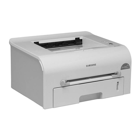
This chapter describes the functions and operating principal of the main component. 4.1 Printer Components 4.1.1 Front View Top output tray (Face down) Output Support Control Panel Front Cover Manual Feeder guide Power switch Manual Feeder Paper level indicator Tray Service Manual Samsung Electronics... -
Page 19: Rear View
S U M M A RY OF PRO D U C T 4.1.2 Rear View Rear output tray (Face up) Power receptacle Parallel port USB port 4.1.3 Inside View Toner cartridge Front Cover Service Manual Samsung Electronics... -
Page 20: Control Panel
If you press this button once again, this LED is off and the Toner Save mode is disabled. If the On Line/Error and Toner Save LEDs blink, your system has some problems. To solve the problem. Service Manual Samsung Electronics... - Page 21 In Manual Feed mode, you can’t cancel the print job by pressing this button. Toner Save mode on/off In Ready mode, press this button to turn the Toner Save mode on or off. Service Manual Samsung Electronics...
- Page 22 S U M M A RY OF PRO D U C T 4.2 System Layout L S U Fuser Toner Cartridge MP Sensor Cassette Fuser Manual Feeder LSU(Laser Scan Unit) Transfer Roller Toner Cartridge PTL(Per-Tramsfer-Lamp) Service Manual Samsung Electronics...
- Page 23 - There are two methods, the existing method which use the Heat Lamp and the Q-PID which is developed by Samsung. 110V : Heat Lamp type Fuser 220V : Heat Lamp type or Q-PID type Fuser 4.2.4.1 Temperature-Intercepting Device (Thermostat)
- Page 24 /HS YNC signal to arrange the vertical line of the image on the paper. After detecting the /HS YNC signal, the image data is sent to the LSU to arrange the its left margin on the paper. The one side of the polygon mirror is one line for scanning. Service Manual Samsung Electronics...
-
Page 25: Toner Cartridge
- Management of disusable toner: Collect the toner by using electric static (Clenerless Type- No disusable toner) - OPC Drum protecting Shutter: None - Classifying device for toner cartridge: ID is classified by interruption of the frame channel. Service Manual Samsung Electronics... - Page 26 The signals from the paper feed jam sensor and paper empty sensor are directly inputted to the main board. VIDEO CLK FLASH 14.7456MHz MEMORY SDRAM BUFFER ASIC CLOCK GENERATOR IC PARELLEL CONN MAIN CLK 10MHz USB CONN COMPARATOR IC MOTOR DRIVER IC OSCI CN10 OSC2 CN2(DCU PORT) Service Manual Samsung Electronics...
-
Page 27: Flash Memory
By operation of Actuator on the frame, the MP Sensor (Photo Interrupter) on the engine board informs the state of paper to CPU whether it is empty or not. It reads the D0 Bit of CPU for recognizing paper in MP, and paper is fed from MP if there is. Service Manual 4-10 Samsung Electronics... - Page 28 The motor driving circuit is formed when the Driver IC is selected in the first place. The A3977 (Motor driver IC) is used in this case. But, the resistance Rs value of sensing and the voltage value of the V reference can be changed by motor driving voltage value. Service Manual 4-11 Samsung Electronics...
- Page 29 (PANEL CON.) 220V : 250V 2A H 220V : 250V T 5A H (H/L CON.) MHV OPC SUPPLY COVER OPEN SWITCH MANUAL SENSOR FEED SENSOR PAPER-EMPTY SENSOR EXIT SENSOR MAIN PBA CON. F101 250V L2A Service Manual 4-12 Samsung Electronics...
- Page 30 - Error: 1. If SUP is GND, a density is dramatically going down. 2. If SUP is floating due to instable contacting point of terminal, and etc., a density is signif- icantly going down as much as it cannot be recognized with eyes. Service Manual 4-13 Samsung Electronics...
- Page 31 1.0 A 0.14A 2.0 A AVG : 250 Wh Sleep-Mode 0.8A 0.01A 0.4A AVG : 10 Wh 4) Length of Power Cord : 1830 ± 50mm 5) Power Switch : Service Manual Training Manual 4-14 4-14 Samsung Electronics Samsung Electronics...
-
Page 32: Fuser Ac Power Control
1) Triac (THY1) feature - 12A,600V SWITCHING 2) Phototriac Coupler (PC3) - Turn On If Current : 15mA ~ 50mA(Design: 16mA) - High Repetive Peak Off State Voltage : Min 600V Service Manual 4-15 Samsung Electronics... - Page 33 AD converter. The voltage value for impressing to the transfer roller is decided by the changed value. Service Manual 4-16 Samsung Electronics...
- Page 34 The temperature after the 3 seconds is checked. If it is over 240°C, it is error. • If the temperature has been higher than 220°C over 25 seconds, it is an error even through the temperature doesn’t reach 240°C. Service Manual 4-17 Samsung Electronics...
- Page 35 4.5.4.3 What is the Q-PID Method? The Q-PID is developed by Samsung, and it saves the preheating time in half in comparison with the existed method. It saves not only the printing time for initial print but also it saves the printing speed for the reat- tempting print after for a while.
-
Page 36: Disassembly And Reassembly
3. Unplug the power cord. 4. Use a flat and clean surface. 5. Replace only with authorized components. 6. Do not force plastic-material components. 7. Make sure all components are in their proper position. Service Manual Samsung Electronics... -
Page 37: Top Cover
2. Remove the Front Cover in the direction of 5. Remove the Top Cover in the direction of arrow. arrow. Top Cover Front Cover 3. Remove four screws. 6. Remove the Rear Cover from the Top Cover. Rear Cover Service Manual Samsung Electronics... - Page 38 3. Remove two screws and take the Thermostat out of the Fuser. Thermostat 7. Remove the Thermister from the Fuser Cover. 4. Remove two screws and take the Halogen Lamp out of the Heat Roller. Heat Roller Thermister Halogen Lamp Service Manual Samsung Electronics...
-
Page 39: Exit Roller
- Top Cover(see page 5-2) 2. Remove two screws and unplug one connector from the Frame. 5. Unplug four screws and take the LSU out. 3. Remove the LED PBA Ass’y as shown below. LED PBA Cover Service Manual Samsung Electronics... - Page 40 5.7 Driver Ass’y 1. Before you remove the Fuser, you should 3. Unplug one connector from the Driver Ass’y remove: - Top Cover(see page 5-2) Drive Ass'y 2. Remove the six screws from the Drive Ass’y. Service Manual Samsung Electronics...
-
Page 41: Main Pba
1. Before you remove the Fuser, you should remove: - Top Cover(see page 5-2) Main PBA - Engine Shield Ass’y(see page 5-8) 2. Unplug one connector and remove five screws from the Main PBA. Then lift the Main PBA out, as shown below. Service Manual Samsung Electronics... - Page 42 - Top Cover(see page 5-2) - Engine Shield Ass’y(see page 5-8) 2. Unplug one connector and remove three screws then take the Inlet Ass’y out. Inlet Bracket 4. Remove three screws and take The SMPS out. SMPS Service Manual Samsung Electronics...
-
Page 43: Transfer Roller
- LSU(see page 5-6) Lens Holder 2. Remove three screws and take the Transfer Earth out. Transfer Earth 4. Unlatch the Bush and remove it. Then lift the Transfer Roller out, as shown below. Transfer Roller Bush Service Manual Samsung Electronics... -
Page 44: Feed Roller
Ass'y Feed Idle Shaft Bush 7. Remove the Feed Roller and Feed Roller 1, as shown below. 4. Remove three screws from the Feed Bracket Feed Roller and take it out. Feed Bracket Feed Roller1 Service Manual Samsung Electronics... - Page 45 Pick up Ass'y 5. Remove two screw then remove The Manual Solenoid and Pick Up Solenoid. 3. Remove the Pick up Gear Ass’y, as shown below. Pick up Gear Ass'y (Pick up) Solenoid (Manual) Solenoid Service Manual 5-10 Samsung Electronics...
-
Page 46: Alignment And Adjustments
COVER OPEN ERROR NO PAPERR PAPER JAM 0 PAPER JAM 1 PAPER JAM 2 LSU NOT READY DIAGNOSTIC DOWN SHIFT STOP MODE ENTER TO ENTER DIAGNOSTIC MODE, PUSH THREE BUTTONS SIMUL ANEOUSL AND TURN THE PRINTER POWER ON. Service Manual Samsung Electronics... - Page 47 The front part of paper is jammed just after passing through the discharge sensor. Out Bin Full The Out bin is filled with paper. LSU Not Ready LSU Scanner Motor not ready or Hsync signal not output. Service Manual Samsung Electronics...
- Page 48 [Up] button to Check LD. LD is functioning and the middle button is on. If the LD is normal, all LEDs are on. Pickup clutch on The Solenoid in the printer is in operation. To stop the operation, Press the button [shift] and [Enter] together. Service Manual Samsung Electronics...
- Page 49 Indicates the function of the Fan, same method of the code ‘07’. Manual Pickup Test : Indicates the function of th Manual Pickup, same method of the code ‘07’. Manual Sensor Test : Indicates the function of the Manual Sensor, same method of the code ‘07’. Service Manual Samsung Electronics...
- Page 50 READY Mode, and '88' shows in the DCU. In this mode, without any detection, the printer begins printing(trial printing and data from the PC). It is convenient to use this mode when the engine malfunction is detected in the control board. Service Manual Samsung Electronics...
-
Page 51: Paper Path
4) The paper passed the paper exit sensor moves out from the set. (Jam 2 occurs sometime after if the tail- ing edge of the paper is not coming out from the set after the leading edge of paper passes the paper exit sensor.) Service Manual Samsung Electronics... -
Page 52: Clearing Paper Jams
The inside of the printer is still hot. pulling. Continue with the next step. 2) Open the rear output tray. 4) Close the rear output tray. Open and close the front cover. Printing can be resumed. Service Manual Samsung Electronics... - Page 53 1) Open the front cover and remove the toner cartridge 2) Gently pull the paper toward you. 3) Check that there is no other paper in the printer. 4) Reinstall the toner cartridge, and then close the cover. Printing can be resumed. Service Manual Samsung Electronics...
-
Page 54: Tips For Avoiding Paper Jams
• Do not use creased, damp or highly curled paper. • Do not mix paper types in the input tray. • Use only recommended print media. • Ensure that the recommended print side is facing down when loading paper into the input tray. Service Manual Samsung Electronics... -
Page 55: Sample Pattern
1) Hold down the Cancel button for about 2 seconds to print a demo page. Hold down the Cancel button for about 6 seconds to print a configuration sheet. <Demo Page : ML-1710> <Demo Page : ML-1750> Service Manual 6-10 Samsung Electronics... - Page 56 IEEE1284 and USB 1.1 interfaces www.samsungprinter.com e v e r y o n e ’ s i n v i t e d **AII other trademarks are the property of their respective owners. Samsung Electronics, AII rights reserved. Service Manual 6-11 Samsung Electronics...
-
Page 57: Printing A Cleaning Sheet
3) Your printer automatically picks up a sheet of paper from the tray and prints out a cleaning sheet with dust or toner particles on it. Note: The cartridge cleaning process takes some time. To stop printing, turn the power off. Service Manual 6-12 Samsung Electronics... -
Page 58: Consumables And Replacement Parts
(Pmotor Error) simultaneously flashing every one-second. LSU Not Ready Error The printing is stop in the fad status, and the [Error] LED (green) and (HSYNC Error) the [Toner Save] LED are simultaneously flashing every 4 seconds. Service Manual 6-13 Samsung Electronics... -
Page 59: Periodic Defective Image
L S U Fuser Toner Cartridge MP Sensor L S U Tramsfer Roller OPC Drum Fuser Toner Cartridge Heat Roller Charge Roller MP Sensor Pressure Roller Supply Roller Developing Roller <Rollers Layout> Service Manual 6-14 Samsung Electronics... - Page 60 LIGNMENT & D J U S T M E N T S Service Manual 6-15 Samsung Electronics...
-
Page 61: Troubleshooting
4. No. 4. : Open the front cover and check odically at the top of a black image. ribs that corresponds to the position of the voids. Remove if found. 5. If the problems are not solved, replace the developer cartridge. Service Manual Samsung Electronics... -
Page 62: Horizontal Black Band
1, take measures as to replace the develop- er cartridge and try to print out. 5. Clean the inside of the set against the paper particles and foreign matter in order not to cause the trouble. Service Manual Samsung Electronics... -
Page 63: Light Image
HVPS. in the side of the Developer and charge terminal of HVPS. 3. Replace the HVPS if not solved by the above direction 1 and 2. Service Manual Samsung Electronics... -
Page 64: Uneven Density
4. Is the movement(Up and Down) of 4. Clean the bushing part of the transfer the transfer roller smooth? roller. 5. Is the HVPS normal? 5. If the problem is still not solved, replace the developer. Service Manual Samsung Electronics... - Page 65 Digital Printer mal paper or transparencies such as OHP, the software application and after using return- Digital Printer higher transfer voltage is required. ing to the original mode is recommended. Digital Printer Digital Printer Digital Printer Service Manual Samsung Electronics...
- Page 66 2. If the transfer roller is contaminated, satins 2. If the transfer roller is contaminated, run PC on the face of page will occur. Cleaning Mode Print 2 or 3 times. Digital Printer And perform Self-Test 2 or 3 times to remove contamination. Service Manual Samsung Electronics...
- Page 67 2. Perform the engine self test using DCU to check if the Solenoid is normal.(refer to code 06) 3. If not solved by the above directions 1-2, Replace the engine board. 4. Turn the power off, delete the data of PC and try printing again. Service Manual Samsung Electronics...
-
Page 68: Bad Discharge
3. Clean with soft cloth dampened with IPA(Isopropyl ter. Alcohol) or water. 4. If the paper feeds into the printer rand Jam 0 occurs, 4. Replace the SMPS-HVPS and/or Sensor. perform DCU to check feed-sensor of the engine board. Service Manual Samsung Electronics... - Page 69 3. Remove the jammed paper after disassembling the fuser : Clean the surface of the pressure roller with dry gauze. • Remove the toner particles stained on the rib. • Check the assemblage and performance of the exit. Service Manual Samsung Electronics...
- Page 70 3. The surface of the heat roller with IPA or water 4. Check the warp or separation of the sprint claw and the holder plate claw, and then man- age it. Service Manual 7-10 Samsung Electronics...
- Page 71 2. How to remove the rolled in the OPC Drum. • Remove the paper while turning the OPC Drum against the ongoing direction. • C;eam fomger[romts on the OPC Drum spft;u with IPA(Isopropyl Alcohol) or tissue. Service Manual 7-11 Samsung Electronics...
- Page 72 Solution DCU Mode : Perform DCU diagnostic code 05. If the DCU Replace LSU. error code 95 is displayed, replace LSU. If you cannot solve the problem after you replace LSU, replace the main board. Service Manual 7-12 Samsung Electronics...
-
Page 73: Paper Empty
1. Bending or deformation of the actuator of the paper sen- 1. Replace the defective actuator. sor. 2. The function of the engine board is defective Perform. 2. Replace the engine board. DCU mode : Perform DCU diagnostic code 8. Service Manual 7-13 Samsung Electronics... -
Page 74: Cover Open
Main Control board. Perform DCU Connect. mode : If Error state '64' occurs, Check the related codes of the Cover Open Error 2. Replace the Main Control board or Cover Open S/W. Service Manual 7-14 Samsung Electronics... -
Page 75: Defective Motor Operation
1. Replace the power supply cord or SMPS. 2. Check the inferiority of LED-Panel on the front-cover if 2. Replace the control board. the LED of Panel does not appear after normal warming- 3. Replace the LED-panel. Service Manual 7-15 Samsung Electronics... -
Page 76: Vertical Line Getting Curved
1. If the supply of +24v is unstable in the Main Control board 1. Replace LSU. linking with LSU, check drive by DCU Mode : LSU Check -05- LSU Motor on. 2. Replace the Main Control board. Service Manual 7-16 Samsung Electronics... -
Page 77: Redistributing Toner
7.4 Toner Cartridge Service It is not guaranteed for the default caused by using other toner cartridge other than the cartridge supplied by the Samsung Electronic or caused by non-licensed refill production. 7.4.1 Precautions on Safe-keeping of Toner Cartridge Excessive exposure to direct light more than a few minutes may cause damage to the cartridge. - Page 78 (1)Check whether foreign sub- stances or toner are stuck to the terminal (contact point) of the developer. (2)Check whether the state of the terminal assembly is normal. 3. If it cannot be recycled: Replace the developer. Service Manual 7-18 Samsung Electronics...
- Page 79 2 times. (2)Check whether the state of (2)If toner nearly being expired the terminal assembly is nor- are collected to use, it is mal. judged as the recycled devel- oper. Service Manual 7-19 Samsung Electronics...
- Page 80 4. If the scanner needs to be connected to the printer, 4. Check if the printer cable is directly connected to periph- first the remove the scanner from the PC to see if the eral devices printer is properly working alone. Service Manual 7-20 Samsung Electronics...
- Page 81 Turn the PC and printer off, and reboot the system to print again. If not solved, double-click the printer in my computer If the regular fonts are not printed this time again. the cable must be defective so replace the cable with new one. Service Manual 7-21 Samsung Electronics...
-
Page 82: Abnormal Printing
3. Delete the unnecessary files to secure enough (The printing job sometimes stops or due to insufficient space of the hard disk and start printing job again. virtual memory, but it actually comes from the insuffi- cient space of the hard disk.) Service Manual 7-22 Samsung Electronics... -
Page 83: Spool Error
Before choosing the document, the menu is still inactive. Or put the document out of the list and repeat the routine as in the above or finish the spool manager. Service Manual 7-23 Samsung Electronics... -
Page 84: Exploded Views And Parts List
EXPLODED VIEW & PARTS LIST 8. Exploded Views and Parts List(ML-1740/XSH) 8-1. Main Assembly ....... page(8-2) 8-2. -
Page 85: Main Assembly
EXPLODED VIEW & PARTS LIST 8.1 Main Assembly Service Manual Samsung Electronics... - Page 86 EXPLODED VIEW & PARTS LIST Main Assembly Parts List SA : Service Available O : Service available X : Service not available Description SEC.Code Q’ty Remark ML-1740/XSH ELA UNIT-FRAME LOWER, 220V JC96-02734A ML-1740 MEA UNIT-COVER TOP JC97-01901A ML-1740 LENS LED-M-LED...
-
Page 87: Frame Unit Assembly
EXPLODED VIEW & PARTS LIST 8.2 Frame Unit Assembly Service Manual Samsung Electronics... - Page 88 IPR-P-GROUND_EARTH TR JC70-00309A SPRING-ETC 6107-001162 ROLLER-FEED ROLLER 1 JC66-00526A PMO-BUSHING FEED JC72-00382B ROLLER-FEED JC66-00598A SPRING-TS 6107-001165 Spring-act,Manual IPR-P-EARTH TRANSFER JC70-00307A HOLDER-PTL JC61-00583A LENS-PTL JC67-00027A BUSH-M-TR L JC61-00588A SPRING ETC-TR L HAWK JC61-00047A SPRING-TS 6107-001165 Spring-act,Feed PMO-BUSHING_TR(L) JC72-00102A Service Manual Samsung Electronics...
- Page 89 JC72-01231A 58-6 BUSH-M-PICK_UP R JC61-00587A 58-7 HOUSING-M-PICK_UP JC61-00591A MEA UNIT-CLUTCH JC97-01788A 59-1 GEAR-FEED 1 JC66-00393A 59-2 PMO-COLLAR_SPRING JC72-00978A 59-3 SPRING-TS 6107-001165 59-4 PMO-HUB CLUTCH JC72-00981A ELA HOU-FUSER 220V JC81-01690A 220V RMO-RUBBER EXIT JC73-40915A PBA MAIN-PTL JC92-01440A Service Manual Samsung Electronics...
-
Page 90: Drive Unit Assembly
Description SEC.Code Q’ty Remark ELA UNIT-RX DRIVE JC96-02733A BRACKET-P-GEAR 1400 JC61-00598A GEAR-RDCN 53/26 JC66-00388A GEAR-RDCN 113/33 JC66-00391A GEAR-RDCN 57/18 JC66-00389A WASHER-PLAIN 6031-000023 BRACKET-P-MOTOR 1400 JC61-00599A GEAR-RDCN 103/41 JC66-00390A GEAR-RDCN 90/31 JC66-00392A MOTOR STEP-HUMMINGBIRD JC31-00028A PMO-IMPELLER_DRV JC72-00825A Service Manual Samsung Electronics... -
Page 91: Cassette Unit Assembly
EXPLODED VIEW & PARTS LIST 8.4 Cassette Unit Assembly Service Manual Samsung Electronics... - Page 92 SPRING-CS 6107-001166 HOLDER-M-PAD JC61-00580A SPRING ETC-EXIT ROLL FD JC61-70911A ROLLER-M-IDLE FEED JC66-00529A SPRING-ES 6107-001047 PMO-PLATE_LOCKER JC72-00972A SPRING ETC-LOCKER,PLATE JG61-70531A ADJUST-M-CASSETTE_L JC70-00300A ADJUST-M-CASSETTE_R JC70-00301A GEAR-PINION JG66-40003A INDICATOR-LEVER-HREFRESH JC64-00134A RPR-FRICTION PAD JC73-00140A IPR-PLATE PAD JC70-00314A RPR-PAD CASSETTE JC73-00141A Service Manual Samsung Electronics...
-
Page 93: Fuser Unit Assembly
EXPLODED VIEW & PARTS LIST 8.5 Fuser Unit Assembly Service Manual 8-10 Samsung Electronics... - Page 94 4713-001183 220V ROLLER-M-EXIT F/UP JC66-00380A ROLLER-PRESSURE JC66-00600A BEARING-PRESSURE/R JC66-10901A SPRING-CS 6107-001169 PMO-BUSHING TX JC72-00382A HOLDER-ACTUATOR JC61-00581A PMO-ACTUATOR_EXIT JC72-00987A IPR-P-FRAME_FUSER JC70-00317A GUIDE-M-INPUT JC61-00595A SPRING-TS 6107-001171 RMO-RUBBER_EXIT JC73-00017A NUT-HEXAGON 6021-000222 LABEL(P)-CAUTION, HOT_FUSER JC68-30928D PMO-FUSER_EXIT JC72-01298A PLATE-P-CLAW JC61-00605A Service Manual 8-11 Samsung Electronics...
- Page 95 EXPLODED VIEW & PARTS LIST Service Manual 8-12 Samsung Electronics...
-
Page 96: Block Diagram
B LOCK DIAG R A M 9. Block Diagram 9.1 GDI Model Service Manual Samsung Electronics... -
Page 97: Connection Diagram
FR-4, 2L 3.3V 3.3V THERM THERM2 THERMISTOR SMPS MOTOR 24VS 24VS MANUAL CN10 24VS LED_READY HVPS THV_READY 3.3V LED_ERROR DCU DATA THV_PWM DCU CLK THV_EN BIAS_PWM MHV_PWM PANEL LED_TSAVE 3.3V KEY_IN SENSOR UART FUSER_ON EXIT Service Manual 10-1 Samsung Electronics...