Advertisement
Quick Links
Download this manual
See also:
Operating Manual
Technical Supplement
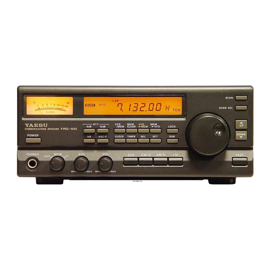
FRG-100
YAESU MUSEN CO., LTD.
YAESU U.S.A.
17210
YAESU EUROPE B. Vi
Snipweg
Tokyo, Japan
1500,
Edwards Rd., Cerritos, California 90701, U.S.A.
Advertisement

Related Manuals for Yaesu FRG-100


Summary of Contents for Yaesu FRG-100
- Page 1 FRG-100 Technical Supplement YAESU MUSEN CO., LTD. Tokyo, Japan 1500, YAESU U.S.A. Edwards Rd., Cerritos, California 90701, U.S.A. 17210 YAESU EUROPE B. Vi Snipweg...
- Page 2 Contents . - -. . - -..*..... . l-3 Main Unit 2 - l 2 - l Local Unit Display Unit Pilot Lamp &...
- Page 3 This manual provides technical inf orma- While we believe the technical information tion necessary for servicing the FRG-100 gen- in this manual to be correct, Yaesu assumes no ral coverage communications receiver. It does liability for darnage that may occur as a result...
- Page 4 Chip Component Information The diagrams below indicate some of the distinguishing features of common Chip com- ponents. Ceramic Capacifors (Unit Type Negati Resistors Multiplier 10’s unit 10’ INDICATED LETTERS 1 2 3 4 10’ 1 OS Examples 100 = ion 222 = 2.2kn 473 = 47k0...
- Page 5 Chip Component Information Chip components are installed at the fac- not disconnect a Chip forcefully, or the foil Pattern may peel off the board. a small spot of adhesive resin at the location Never re-use a Chip component. Dispose of where each part is to be installed, and later all removed chip components immediately to robots handle and place Parts using vacuum...
- Page 6 Chip Component Information As the value of some Chip components is not indicated on the body of the Chip, be care- one side where the chip is to be installed. Avoid too much solder, which may Cause bridging (shorting to other Parts). Position, and apply the soldering iron with a motion line as indicated by the arrow in the diagram below.
-
Page 7: Main Unit
Case Disassembly & Circuit Board Access Main Unit To access the local unit, remove the 8 screws bles. affixing the bottom cover (Figure 3). remove the 8 screws affixing the top cover (Figure 1). Figure 3. To remove the local unit, remove the 7 screws affixing the unit, and the 2 screws used on the Figure 1. -
Page 8: Display Unit
Case Disassembly & Circuit Board Access Display Unit 0 Remove the wiring connectors from the SQL tiometer, squelch, rotary encoder and head- and VOL controls on the rear of the Display phone jack), remove both the top and bottom Unit. the 2 middle screws from both edges on each with the tab on the Display Unit circuit board side of the display unit (Figure 1). -
Page 9: Resetting The Microprocessor
There are two ways to reset the CPU in the FRG-100, both of which clear the contents of Battery replacement all memories, leaving them at the factory de- The lithium backup battery tan be re- faults. - Page 10 Case Disassembly & Circuit Board Access Hard Reset power Source. Turn the BACK UP switch on the rear Panel to OFF. Reconnect the DC power Source, then turn the receiver back on. BACK UP BACK Ul? SWITCH...
-
Page 11: Circuit Description
QlO38 and delivered to 00 for detection(when circuits of the FRG-100. Such an under- the optional FM standing is necessary for troubleshooting the installed) For other modes, the 455 kHz Signal... - Page 12 Circuit Description delivery to mixer Q2012 (uIIX1037H)This sig- Potentiometer VR3601 located on the VR Unit. A Sample of the pre-amplified audio @ 600 &2 is also delivered to the REC jack on the low-pass filtered, buffered by Q2021(2SK192) rear Panel. and amplified by Q2024 (2SC535) before be- ing returned to PLL IC Q2030.
- Page 13 Circuit Description filtered before amplification by Q2019 of Q2030) controlled by Q2027 (BAlA4P) sig- main loop Q2012 (uPC1037H) as a sub-loop nals the CPU, which then mutes receiver audio and blinks the display until the PLLs resume leck. Although the reference frequency of the main loop is 81.92 kHz, a 10 Hz receiving The MPU provides band (BPF) selection on frequency step is obtained by mixing a sub-...
- Page 14 The FRG-100 is carefully designed to allow The following test equipment (and thor- the knowledgeable Operator to make nearly ough familiarity with it’s correct use) is neces- sary for complete realignment. Correction of all adjustments for various Station conditions, the Problems caused by misalignment result-...
- Page 15 Alignment Only one extender board (if optional) vco3 should be installed at a time for access to the 0 Tune the receiver to 14.499 MHz in USB board being aligned. Also, the test equipment mode. must be thoroughly warmed up before begin- 0 Adjust L2005 for 7.0 V ti.l V.
- Page 16 Alignment age on the meter (adjust the injection level as (4) S-Meter Full-Scale necessary). (6) SSB Squelch Threshold 0 In the USB mode, with no Signal at the an- tenna jack, set the SQL control to the ll- (5) Noise Blanker o’clock Position, and adjust VR1004 so that the squelch just closes.