Table of Contents
Advertisement
Advertisement
Table of Contents

Related Manuals for Control 4 CCZ-T1-W


Summary of Contents for Control 4 CCZ-T1-W
- Page 1 Wireless Thermostat Installation Guide...
- Page 2 Control4 reserves the right to make changes to any and all parts of Control4 hardware, software, and this publication at any time, without any obligation to notify any person or entity of such changes.
-
Page 3: Table Of Contents
Table of Contents Supported Model ......................1 Important Safety Instructions ................... 1 General Description ...................... 1 Box Contents ........................2 Requirements ........................2 Specifications ......................... Pre-Installation Considerations ................4 Installation Instructions....................7 Composer Programming Instructions ..............11 Thermostat Relays ......................16 Troubleshooting ...................... -
Page 5: Supported Model
IMPORTANT! Using this product in a manner other than outlined in this document voids your warranty. Further, Control4 is NOT liable for any damage incurred with the misuse of this product. See the warranty information in the Control4 Wireless Ther- mostat User Guide or on the Control4 website at www.control4.com/warranty. -
Page 6: Box Contents
3 plastic wall anchors (#4-6 x 7/8”) • Warranty card • U-shaped terminal jumper wire • Power-stealing bypass resistor (270 Ohm) • Control4 Wireless Thermostat Installation Guide (this document) Requirements • Pencil (#2 or darker) • Drill with 3/16” drill bit • Small level (optional) •... -
Page 7: Specifications
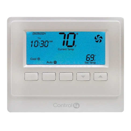
Specifications Front and Rear View Figure 1. Faceplate Figure 2. Rear Plate Recommended Wiring: 22 AWG (36 ft. max.) 18 AWG (100 ft. max.) Power Source: 24VAC and 3 volt battery Power Usage: 1/10W at 24VAC, 50/60 Hz Set Point Temperature Range: 40˚ F to 90˚ F (5˚ C to 32˚ C) Operating Temperature: 39˚... -
Page 8: Pre-Installation Considerations
The Wireless Thermostat can be configured to operate in a ‘power stealing’ condition when there is no availability of a dedicated common wire. However, Control4 recommends using a dedicated common wire whenever possible. With some HVAC systems, power stealing can re- sult in system contention between the Cool and Heat Modes, and will render the HVAC system inoperable. - Page 9 • New construction, Control4 recommmends these options: • Install a common wire. • Use a Remote Temperature Sensor in the wall where the Thermostat is located. Run a wire to the furnace, and then install the Thermostat next to the furnace.
-
Page 10: Remote Temperature Sensor
Zoned Systems Control4 supports zoned HVAC systems using a zoning panel. If used, however, a common wire needs to be installed at the Thermostat. Power stealing is not an option in this case. Remote Temperature Sensor A Remote Temperature Sensor allows the Thermostat to get its temperature readings from an area where the Thermostat is not physically located. -
Page 11: Installation Instructions
Installation Instructions Place the Wireless Thermostat in a proper location to ensure its efficiency and to avoid unnecessary cycling of the furnace or air conditioner. Place the Thermostat (or remote temperature sensor) away from direct sun- light, drafts, exterior doorways, skylights, windows, and exterior walls. Make sure the Thermostat gets strong ZigBee wireless reception: (1) Ensure that the Thermostat is within 150 feet of another Zigbee device. - Page 12 Remove the Control4 Wireless Thermostat from the packaging, and detach the rear plate from the Thermostat. (Press the release clip at the bottom of the Thermostat to release it, and then swing the bottom of the Thermostat up.) Thread the wires from the wall through the back of the large rectangu- Figure 3.
- Page 13 Select the desired power supply method by enabling or disabling power stealing on the back of the Thermostat faceplate. • Disable (recommended). Power stealing is disabled and the Thermostat requires the HVAC common wire connection for a dedicated power supply. •...
- Page 14 Test the Thermostat in both the Auto and Manual modes to confirm that both the furnace and air conditioner cycle on and off at the appropriate settings. To operate the Thermostat, see the Control4 Wireless Thermostat User Guide on the Documentation page of the Con- trol4 website at http://www.control4.com/residential/products/resources/ for Thermostat...
-
Page 15: Composer Programming Instructions
Composer Programming Instructions All advanced programming must be completed by a Control4 Dealer using Composer Pro. To see what advanced programming options are available as part of the Control4 system, follow these instructions. The Wireless Thermostat User Guide is available in the Documentation page at http: //www.control4.com/residential/products/resources/ which includes basic Thermostat pro-... - Page 16 Properties Fahrenheit or Celsius: Sets the temperature display in Fahrenheit or Celsius. View/Edit Schedule: Select to access and edit the Thermostat schedule. Vacation: Select to adjust the vacation heat and cool setpoints. Use Remote Temperature Sensor: If unchecked (default), the Thermostat will use the on-board local temperature sensor.
- Page 17 Date Format: Sets the format preferences for date (MM/DD/YYYY or DD/MM/YYYY). Time Format: Sets the format preferences for time (12h or 24h). Sync Time: Synchronizes the time displayed on the Thermostat with the Control4 Controller. Synchronization automatically occurs daily. Network Displays nformational boxes that provide ZigBee networking information (MAC and Firmware Version).
- Page 18 to 2 degrees, the heating system will engage until reaching 70 degrees Fahrenheit. Cooling Cutoff Point: Sets the temperature for the cooling system to turn off past the setpoint. To adjust, use the up and down arrows and press Set Cool Cutoff to confirm the change. Example: If the Cool Point is set to 68 degrees Fahrenheit, and the Cooling Cutoff Point is set to 2 degrees, the cooling system will engage until reaching 66 degrees Fahrenheit.
- Page 19 NOTE: For multistage systems, the deltas for the first and second stages are cumula- tive. If the first stage delta is set at 2 degrees, and the second stage delta is set at 2 degrees, the second stage will not engage until the current temperature has passed the stage setpoint by 4 degrees.
-
Page 20: Thermostat Relays
NOTE: If set to the maximum time, the main heat pump stage and the auxiliary heat stage will run together indefinitely. Thermostat Relays This section shows the relays that are engaged during heating and cooling for the various Wire- less Thermostat configurations. Conventional Stage: Heating Primary Fan (Fuel), Secondary Fan (Fuel) Stage... - Page 21 Primary Fan (Electric), Secondary Fan (Electric) Stage 1st Stage 2nd Stage • The switch in the fuel position causes the Thermostat to deactivate the “G” fan relay, allowing the furnace to control the fan. • The switch in the electric position causes the Thermostat to activate the “G” fan relay, allowing the Thermostat to control the fan.
- Page 22 Primary Fan (Fuel), Secondary Fan (Electric) Stage 1st Stage 2nd Stage Primary Fan (Electric), Secondary Fan (Electric) Stage 1st Stage 2nd Stage Heat Pump: Heating Primary Fan (Fuel), Secondary Fan (Fuel) Stage 1st Stage 2nd Stage 3rd Stage (Before Aux Stage Delay) (If Stage 2 is engaged) 3rd Stage (After...
- Page 23 Primary Fan (Electric), Secondary Fan (Fuel) Stage 1st Stage 2nd Stage 3rd Stage (Before Aux Stage Delay) Auxiliary Stage (After Aux Stage Delay) E-Heat (Stage 1) Primary Fan (Fuel), Secondary Fan (Electric) Stage 1st Stage 2nd Stage 3rd Stage (Before Aux Stage Delay) 3rd Stage (After Aux Cutoff Delay)
- Page 24 Primary Fan (Electric), Secondary Fan (Electric) Stage 1st Stage 2nd Stage 3rd Stage E-Heat (Stage 1) • The Primary Fan switch selects the operating mode for auxiliary heat. • The switch in the electric position indicates that the heat pump is connected to an air handler system, and the Thermostat will control the ‘G’...
- Page 25 Heat Pump: Cooling Primary Fan (Fuel), Secondary Fan (Fuel) Stage 1st Stage 2nd Stage Primary Fan (Electric), Secondary Fan (Fuel) Stage 1st Stage 2nd Stage Primary Fan (Fuel), Secondary Fan (Electric) Stage 1st Stage 2nd Stage Primary Fan (Electric), Secondary Fan (Electric) Stage 1st Stage 2nd Stage...
-
Page 26: Troubleshooting
9 times, middle button 4 times, right button 9 times. The Thermostat must be rebooted after changing switches so that it recognizes the changes. For help on the installation or operation of the Wireless Thermostat, email support@control4. com, check the Technical Support page at http: //www.control4.com/residential/products/ resources/, or call the Control4 Technical Support Center. -
Page 27: Installing A Bypass Resistor To Enable Power Stealing On A Wireless Thermostat
Bypass Resistor Instructions Included in the packaging of each Control4 Wireless Thermostat is a 270 Ohm 3W resistor. Fol- lowing the steps below, connect the resistor to the HVAC system to provide a bypass path from... - Page 28 Figure 6. Bypass Resistor Access the 24V transformer and integrated control panel on the HVAC system. This typically requires removing the front panel of the furnace. Remember to turn OFF the power to the HVAC system before accessing the transformer. Install the resistor on the HVAC system, not on the Thermostat.
- Page 29 Figure 7. Gas/Electric Single Stage...
- Page 30 Loosen the screw on the heat terminal (typically marked ‘W’ or ‘W1’) and secure one end of the resistor in the HVAC system’s Heat Relay Terminal by tightening the terminal screw. Connect the other end of the resistor to the 24V common return path. Two com- pleted wiring examples are shown below.
- Page 31 Example 2. This second example (Figure 9) shows a control board that does not provide a common wire screw terminal. In this example, an additional length of wire was added to the resistor which allowed it to connect from the ‘W’ terminal to the connector for the 24V com- mon that connects from the HVAC transformer to the control board.
-
Page 32: Sample Wiring Configurations
WARNING! Do not install LINE VOLTAGE wires to a LOW VOLTAGE wire. IMPORTANT! When utilizing power stealing, Control4 recommends installing the included 270 Ohm bypass resistor on the HVAC system to minimize any potential side effects. See the previous section “Installing a Bypass Resistor to Enable Power Stealing on a Wireless Thermostat.”... -
Page 33: Wiring Connections
Wiring Connections To see which relays are triggered when certain modes of the Thermostat are called for, see “Additional Information” and “Thermostat Relays” described previously. Terminal Description 24VAC power for heating—connect to low voltage heating system transformer. (See Note 1 below.) 24VAC power for cooling—connect to low voltage cooling system transformer. - Page 34 Figure 10. Conventional, Single Stage Wiring...
- Page 35 Figure 11. Conventional, Dual Stage Wiring...
- Page 36 Figure 12. Heat Pump, Single Stage Wiring...
- Page 37 Figure 13. Heat Pump with Electric Auxilliary Heat, Dual Stage Wiring...
- Page 38 Figure 14. Millivolt Heat, Conventional Cool, Single Stage Wiring...
- Page 39 Figure 15. Heat Pump with Electric Auxilliary, Dual Stage, Dual Transformer Wiring...
-
Page 40: Regulatory Compliance
Regulatory Compliance To review regulatory information for your particular Control4 products, see the information located on the Control4 website at: http://www.control4.com/regulatory/ Warranty Limited 2-year warranty. Refer to http://www.control4.com/warranty.