Lennox O23 Unit Information
O23 / ohr23 / of23 series units
Hide thumbs
Also See for O23:
- Brochure & specs (4 pages) ,
- Installation instructions manual (23 pages)
Advertisement
Table of Contents
- 1 Table of Contents
- 2 General
- 3 Specifications
- 4 Indoor Blower Data
- 5 Parts Arrangement
- 6 I Unit Components
- 7 Placement and Installation
- 8 Start up
- 9 Heating Systems Service Checks
- 10 Disassembling Burner
- 11 Typical Operating Characteristics
- 12 Maintenance
- 13 Wiring Diagrams
- 14 Troubleshooting
- Download this manual
See also:
Instruction and Installation Manual
Service Literature
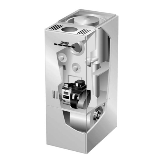
O23 (Elite 80t) series units are mid−efficiency up flow oil fur
naces manufactured with Beckett oil burners. O23 units are
available in heating capacities of 70,000 to 154,000 Btuh
(20.5 to 45.1 kW) and cooling applications from 2 through 5
tons (7.0 through 17.6 kW). Refer to Engineering Hand
book for proper sizing.
OHR23 (Elite 80t) series units are mid−efficiency horizontal /
down flow oil furnaces. The OF23 (Elite 80t) series units are
mid−efficiency lo boy up flow oil furnaces, which come in front
(OF23) or rear (OF23R) flue openings, both with Beckett oil
burners. The OHR23 and OF23(R) units are available in heat
ing capacities of 105,000 to 154,000 Btuh (30.8 to 45.1 kW)
and cooling applications from 2 through 5 tons (7.0 through
17.6 kW). Refer to Engineering Handbook for proper siz
ing.
The drum type heat exchanger comes with strategically
placed ports allowing easy cleaning, while the oil burner
can be removed for inspection and service. The mainte
nance section gives a detailed description on how this is
done.
Information contained in this manual is intended for use by
experienced HVAC service technicians only. All specifica
tions are subject to change. Procedures outlined in this
manual are presented as a recommendation only and do
not supersede or replace local or state codes.
WARNING
Electric shock hazard. Can cause injury
or death. Before attempting to perform
any service or maintenance, turn the
electrical power to unit OFF at discon
nect switch(es). Unit may have multiple
power supplies.
WARNING
Improper installation, adjustment, alteration, ser
vice or maintenance can cause property damage,
personal injury or loss of life. Installation and service
must be performed by a qualified installer or service
agency.
Corp. 9535−L8
Revised 09/2003
O23 / OHR23 / OF23 SERIES UNITS
Page 1
O23 SHOWN
TABLE OF CONTENTS
. . . . . . . . . . . . . . . . . . . . . . . . . . . . . . . . . . . . . .
. . . . . . . . . . . . . . . . . . . . . . . . . . . . . . . . .
. . . . . . . . . . . . . . . . . . . . . . . . . . . .
. . . . . . . . . . . . . . . . . . . . . . . . . . . .
. . . . . . . . . . . . . . . . . . . . . . . . . . . . .
. . . . . . . . . . . . . . . . . . . . . . . . . . . . . . . . . . . .
. . . . . . . . . . . . . . . . . . . . . . . .
. . . . . . . . . . . . . . . . . . . . . . . . . . . . . . .
. . . . . . . . . . . . . . . . . . . . . . . . . .
. . . . . . . . . . . . . . . . . . . . . . . . . . . .
O23/OHR23
OF23
. . . . . . . . . . . . . . . . . . . .
. . . . . . . . . . . . .
. . . . . . . . . . . . . .
1995 Lennox Industries Inc.
Litho U.S.A.
1
2
4
5
7
16
22
22
24
26
27
28
31
Advertisement
Table of Contents

Related Manuals for Lennox O23


Summary of Contents for Lennox O23
-
Page 1: Table Of Contents
Service Literature Revised 09/2003 O23 / OHR23 / OF23 SERIES UNITS O23 (Elite 80t) series units are mid−efficiency up flow oil fur naces manufactured with Beckett oil burners. O23 units are available in heating capacities of 70,000 to 154,000 Btuh (20.5 to 45.1 kW) and cooling applications from 2 through 5... -
Page 2: Specifications
SPECIFICATIONS − O23 Model Number O23Q2 70 O23Q3 105/120 O23Q5 140/154 Input Btuh (kW) low/high 70,000 (20.5) 105,000 / 120,000 (30.8 / 35.2) 140,000 / 154,000 (41.0 / 45.1) Output Btuh (kW) low/high 57,000 (16.7) 85,000 / 97,000 (24.9 / 28.4) 113,000 / 125,000 (33.1 / 36.6) - Page 3 *Annual Fuel Utilization Efficiency based on U.S. DOE test procedures and FTC labeling regulations. Isolated combustion system rating for non weatherized furnaces. DNozzle must be field provided for field conversion to higher heating input. BLOWER PERFORMANCE DATA − O23 O23Q2 70 BLOWER PERFORMANCE...
-
Page 4: Indoor Blower Data
BLOWER PERFORMANCE DATA − OHR23 OHR23Q3 105/120 BLOWER PERFORMANCE OHR23Q5 140/154 BLOWER PERFORMANCE Air Volume at Various Speeds Air Volume at Various Speeds External Static External Static External Static External Static Pressure Pressure High Medium High Medium in w.g. in w.g. 1470 1360 1070... -
Page 5: Parts Arrangement
O23 GENERAL PARTS ORIENTATION HEAT EXCHANGER VENT OPENING CLEAN OUT PORT LIMIT SWITCH CLEAN OUT PORT CONTROL BOX WITH FAN CONTROL OBSERVATION PORT BECKETT COMBUSTION AIR INTAKE AFII BURNER BLOWER MOTOR INDOOR BLOWER CAPACITOR FIGURE 1 OHR23 GENERAL PARTS ORIENTATION... - Page 6 OF23 GENERAL PARTS ORIENTATION FILTER FRONT VENT OPENING (OF23) INDOOR BLOWER CLEAN OUT PORT LIMIT SWITCH REAR VENT CONTROL BOX OPENING (OF23R) WITH FAN CONTROL HEAT EXCHANGER BECKETT AFII BURNER CLEAN OUT PORT COMBUSTION OBSERVATION PORT AIR INTAKE FIGURE 3 BCC2 / BCC3 BLOWER CONTROL BOARD 120VAC CONTINUOUS FAN...
-
Page 7: I Unit Components
General parts orientation for the O23, OHR23 and OF23 are tory fan off" setting of 150 seconds. Fan off" time will shown in figures 1, 2 and 3 respectively. The O23 and OF23 affect comfort and efficiency and is adjustable to satisfy control box, burner, limit switch and clean out ports may be ac individual applications. - Page 8 Thermostat wires are connected to terminal strip TB1 found on the BCC3 control board. The terminal strip is clearly All O23, OHR23 and OF23−3 and −4 oil units utilize the BCC3 marked with the corresponding thermostat designation. (A15) blower control manufactured by Heatcraft. The BCC3 is...
- Page 9 ST9103A Blower Control Board −5 units 120V All O23, OHR23 and OF23 −5 oil units utilize the ST9103A (A15) blower control manufactured by Honeywell. The ST9103A is a printed circuit board which controls the supply air blower and monitors the limit controls and oil burner opera tion.
- Page 10 −1THROUGH −4 UNIT OIL BURNER PARTS ARRANGEMENT FLANGE AIR TUBE GASKET SCREWS HOLE PLUG ELECTRONIC IGNITION FLANGE TRANSFORMER AIR TUBE RETAINING ASSY FOR CLIP FB HEADS MAIN HOUSING ASSY ESCUTCHEON PLATE CONNECTOR TUBE FB–HEAD HEAD INSULATOR NOZZLE ADAPTER NOZZLE LINE ELECTRODE HEAD ASSY.
- Page 11 −5 UNIT BURNER PARTS ARRANGEMENT ELECTRONIC IGNITION AIR TUBE FLANGE TRANSFORMER SCREWS GASKET FLANGE AIR TUBE RETAINING ASSY FOR CLIP FB HEADS 1/4" HEX MAIN HEAD SCREW HOUSING ASSY ESCUTCHEON PLATE CONNECTOR TUBE FB−HEAD HEAD INSULATOR NOZZLE ADAPTER NOZZLE LINE ELECTRODE HEAD ASSY.
- Page 12 B−Burner (Figures 9 & 10) 3− Pump (−1 through −4 units) The O23, OHR23, and OF23 oil furnaces use the Beckett AFII The O23, OHR23, and OF23 oil furnaces use a single burner. The oil burner provides an atomized oil vapor mixed stage, 3450 RPM pump.
- Page 13 After three consecutive lockouts the control goes into restricted lockout. O23, OHR23 & OF23 −5 Units Only Once flame is established after 10 seconds of run time, the ig Resistance for the cad cell can be checked while the burn niiton shuts off.
- Page 14 (do not forget to put back when test is complete). Place the screwdriver blade across the terminals and slowly raise The primary limit on all O23, OHR23, and OF23 units, is one end of the blade off the terminal while the other re located on the vestibule panel (see figures 1 through 3 for mains in contact with the other terminal.
- Page 15 TABLE 7 1.Blower Motor (B3) and Capacitor (C4) PRIMARY LIMIT CONTROL (S10) All O23, OHR23, and OF23 series units use single phase direct drive blower motors. All motors used are 115V perma ACTUATES ACTUATES UNIT ON TEMP. RISE ON TEMP. FALL nent split capacitor motors to ensure maximum efficiency.
-
Page 16: Placement And Installation
II−PLACEMENT AND INSTALLATION Air Vent OIL PIPING Fill Pipe Make sure unit is installed in accordance with installation in ONE PIPE SYSTEM structions and applicable codes. Î Î Î Î Î Î Î Î Î Î Î Î Fuel A−Piping Î... - Page 17 2− The vent connector should be as short as possible to B−Venting Considerations do the job. WARNING 3− The vent connector should not be smaller than the outlet diameter of the vent outlet of the furnace. Combustion air openings in front of the furnace must be kept free of obstructions.
- Page 18 17− Vent connectors serving this appliance shall not be MASONRY CHIMNEY connected into any portion of mechanical draft sys BAROMETRIC CONTROL* LINER tems operating under positive pressure. (IN EITHER LOCATION) 18− Keep the area around the vent terminal free of snow, ice and debris.
- Page 19 complete combustion which can result in sooting. Require EQUIPMENT IN CONFINED SPACE ments for providing air for combustion and ventilation depend ALL AIR FROM INSIDE CHIMNEY OR largely on whether the furnace is installed in an uncon OIL VENT fined or confined space. Unconfined Space An unconfined space is an area such as a basement or WATER...
- Page 20 EQUIPMENT IN CONFINED SPACE CAUTION ALL AIR FROM OUTSIDE (All Air Through Ventilated Attic) CHIMNEY Combustion air openings in the front of the furnace OR OIL must be kept free of obstructions. Any obstruction VENT VENTILATION LOUVERS (Each end of attic) will cause improper burner operation and may result in a fire hazard or injury.
-
Page 21: Start Up
5− If burner stops after flame is established, repeat the bleeding procedure. NOTE−Air bleeding is automatic on two line applica The O23 is approved for horizontal venting with the fol tions; however, opening air bleed port will allow a faster lowing mechanical vent systems: bleed. -
Page 22: Heating Systems Service Checks
The pump is factory set at 100 psig (689.5 kPa) for the O23Q2−70 and 140 psig (965.3 kPa) for all other O23, OHR23, and OF23 units but is adjustable (see fig ure 28). Never operate the pump in excess of 10 psig (69 kPa) above set point. - Page 23 The following instructions are essential to the proper opera tions, dirty oil, dirt obstructing the air inlet, etc. tion of O23 series oil furnaces. To prevent sooting, these in To build in a window of operation," set up the burner to be...
-
Page 24: Disassembling Burner
7−Stack Temperature IGNITION TRANSFORMER Take a stack temperature reading in the vent connector pipe. SCREWS Subtract the room air temperature from the stack temperature. IGNITION TRANSFORMER This will give you the net stack temperature. Using efficiency charts provided in most CO analyzers you can tell at what ef ficiency the furnace is operating. - Page 25 3−Removing Gun Assembly 5−Removing Motor / Combustion Air Blower 1− Loosen the screw to the back access door until door 1− Disconnect supply line at pump and oil line at gun opens. See figures 30 and 31. assembly as shown in figure 33. 2−...
-
Page 26: Typical Operating Characteristics
B−Temperature Rise ST9103A CONT terminal. Temperature rise for O23, OHR23, and OF23 units depends TABLE 9 on unit input, blower speed, blower horsepower and static BLOWER SPEED SELECTION pressure. -
Page 27: Maintenance
9− Clean the blower wheel and the air control of any lint. Filter handicoater is RP Products coating no. 418 and is avail 10− Check all wiring for secure connections or insulation able as Lennox part no. P 8 5069. breaks. B−Cleaning Heat Exchanger 11−... -
Page 28: Wiring Diagrams
VIII−WIRING DIAGRAMS AND SEQUENCE OF OPERATIONS O23 / OHR23 / OF23−1 through −4 UNIT OPERATION SEQUENCE 1. When disconnect is closed, 120V is routed to the blower 6. A15 energizes accessory relay (K109). When K109 1 control board BCC2 (A15). The BCC2 feeds line voltage closes the accessory terminal on the A15 board is ener to transformer (T1). - Page 29 O23 / OHR23 / OF23−5 UNIT OPERATION SEQUENCE 1. When disconnect is closed, 120V is routed to the blower 6. When heat demand is satisfied, W1 of the thermostat control board (A15). The blower control board feeds line de energizes W of the ignition control. Combustion air voltage to transformer (T1).
- Page 30 TJERNLUND HORIZONTAL VENTING SYSTEM (SIDESHOT) OPERATION SEQUENCE When 1K2 closes, 120VAC is routed through the relay/timer, electronic ignitor (A73), and the limit switch. The relay/timer energizes the venter motor. After the venter motor establishes a draft, the N.O. fan proving switch closes completing the circuit to the burner motor. FIELD CONTROL HORIZONTAL VENTING SYSTEM OPERATION SEQUENCE When 1K2 closes, 120VAC is routed through the relay.
-
Page 31: Troubleshooting
IX−TROUBLESHOOTING Burner failure or improper unit operation can be caused by various conditions. Often the problem can be solved by a logical pro cess of checks and eliminations. The following pages lists a few common problems along with the solutions. Carefully check the most obvious items first before proceeding to more involved procedures. - Page 32 START DOES UNIT OPERATE? BCC2 / BCC3 TROUBLESHOOTING FLOWCHART CHECK: 24VAC ACROSS 1−UNIT POWER R & C? 2−TRANSFORMER 3−LIMIT SWITCH JUMPER ACROSS SCREWS R & G BLOWER REPLACE REPLACE 120VAC ACROSS 120VAC ACROSS RUNNING ON HIGH BCC2 BCC2 N & ACC? N &...
- Page 33 Troubelshooting: Blower Control ST9103A Action System Response Thermostat calls for heat. ST9103A closes oil primary control T−T connections. (W terminal is energized.) Ignition system and oil primary control start the furnace. Oil flows as long as oil primary control senses flame. Burner motor is energized and heat fan on delay timing begins.
- Page 34 Troubleshooting O23 / OHR23 / OF23 −1 through −4 Units Burner fails to start. Source Procedure Causes Correction Thermostat in OFF or COOL Switch to HEAT. Thermostat Check thermostat settings. Turn thermostat to higher tem Thermostat is set too low perature.
- Page 35 Burner starts, but no flame is established. Source Procedure Causes Correction Check tank gauge or use dip No oil in tank Fill tank. stick. Coat dip stick with litmus paste If water depth exceeds 1 inch, Oil Supply Water in oil tank and insert into bottom of tank.
- Page 36 Burner starts and fires, but locks out on safety. Source Procedure Causes Correction Unbalanced fire Replace nozzle Reduce combustion air − check Too much air − −lean short fire If burner con combustion. tinues to run, Increase combustion air − check Too little air −...
- Page 37 Burner starts and fires, but short cycles (too little heat). Source Procedure Causes Correction Heat anticipator set too low Correct heat anticipator setting. Vibration at thermostat Correct source of vibration. Thermostat Thermostat Check thermostat. Check thermostat. Thermostat in the path of a Shield thermostat from draft or warm air draft relocate.
- Page 38 Oil pressure is too low: less Increase oil pressure top than 100 psi. 100psi. Troubelshooting O23 / OHR23 / OF23 −5 Units Procedure Status Correction CONDITION 1: BURNER DOES NOT ENERGIZE WITH A CALL FOR HEAT. 1.1 Check limit switch contacts are Clean contacts.
- Page 39 Troubelshooting O23 / OHR23 / OF23 −5 Units Cont. CONDITION 2: BURNER STARTS, THEN LOCKS OUT ON SAFETY WITH LED FLASHING 1/2 SECOND ON 1/2 SECOND OFF 2.1 Check limit switch contacts are Clean contacts. Replace limit switch if necessary.