Aprilaire 1750A Installation Instructions Manual
Hide thumbs
Also See for 1750A:
- Installation instructions manual (29 pages) ,
- Installation,safety & maintenance manual (16 pages) ,
- Owner's manual (4 pages)
Table of Contents
Advertisement
SAfETy INSTRUCTIONS
1. Improper installation may cause property damage or injury. Installation, service, and maintenance must be performed by a
qualified service technician.
2. 120 Volts may cause serious injury from electric shock. Disconnect electrical power before starting installation or servicing.
Leave power disconnected until installation/service is completed.
3. Sharp edges may cause serious injury from cuts. Use care when cutting plenum openings and handling ductwork.
4. Dropping may cause personal injury or equipment damage. Use tools or two people to transport dehumidifier.
1. Read all instructions before beginning installation.
2. Do not use in pool applications. Pool chemicals can damage the dehumidifier.
3. Do not use solvents or cleaners on or near the circuit board. Chemicals can damage circuit board components.
4. Wait 24 hours before running if the unit has not been shipped or stored in the upright position.
TAblE Of CONTENTS
Safety Instructions . . . . . . . . . . . . . . . . . . . . . . . . . . . . . . . . . . . . . . . 1
Overview . . . . . . . . . . . . . . . . . . . . . . . . . . . . . . . . . . . . . . . . . . . . . . . 2
Specifications . . . . . . . . . . . . . . . . . . . . . . . . . . . . . . . . . . . . . . . . . . . 3
Unpacking and Contents . . . . . . . . . . . . . . . . . . . . . . . . . . . . . . . . . 3
location Considerations . . . . . . . . . . . . . . . . . . . . . . . . . . . . . . . . . . 4
Duct Collars & Backflow Damper . . . . . . . . . . . . . . . . . . . . . . . . . . . 5
Ductwork Recommendations . . . . . . . . . . . . . . . . . . . . . . . . . . . . . . 5
Drain . . . . . . . . . . . . . . . . . . . . . . . . . . . . . . . . . . . . . . . . . . . . . . . . . . 6
Float Switch . . . . . . . . . . . . . . . . . . . . . . . . . . . . . . . . . . . . . . . . . . . . 6
WARNING
CAUTION
READ AND SAVE THESE INSTRUCTIONS
Model 1750A/ 1770A Dehumidifier
Installation Instructions
Installation Configurations
Whole-Home Installation . . . . . . . . . . . . . . . . . . . . . . . . . . . . . . . . . 6
Spot Installation . . . . . . . . . . . . . . . . . . . . . . . . . . . . . . . . . . . . . . . . 8
Convertible Installation . . . . . . . . . . . . . . . . . . . . . . . . . . . . . . . . . . 10
Ventilation or Air Cycling . . . . . . . . . . . . . . . . . . . . . . . . . . . . . . . . 12
Model 70 living Space Control . . . . . . . . . . . . . . . . . . . . . . . . . . . 16
Third-Party Control . . . . . . . . . . . . . . . . . . . . . . . . . . . . . . . . . . . . . 17
System Checkout . . . . . . . . . . . . . . . . . . . . . . . . . . . . . . . . . . . . . . . 18
Troubleshooting . . . . . . . . . . . . . . . . . . . . . . . . . . . . . . . . . . . . . . . . 19
Advertisement
Table of Contents

Related Manuals for Aprilaire 1750A


Summary of Contents for Aprilaire 1750A
-
Page 1: Table Of Contents
Model 1750A/ 1770A Dehumidifier Installation Instructions SAfETy INSTRUCTIONS WARNING 1. Improper installation may cause property damage or injury. Installation, service, and maintenance must be performed by a qualified service technician. 2. 120 Volts may cause serious injury from electric shock. Disconnect electrical power before starting installation or servicing. -
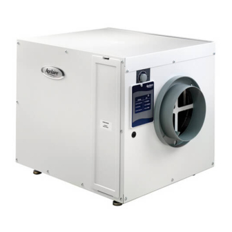
Page 2: Overview
OVERVIEW The Aprilaire Dehumidifier is designed to control humidity inside the whole home . The dehumidifier uses a dew point calculation to control the ® humidity based on the dryness set point on the dehumidifier control . An optional Model 70 Living Space Control or third-party control can be used in place of the onboard control . -
Page 3: Specifications
Weight: 1750A – 93 lbs . External Static Pressure Airflow 1770A – 100 lbs . Capacity: 1750A – 90 pints per day @ 275 CFM 0 .0 “w .c . 385 CFM 1770A – 135 pints per day @ 500 CFM 0 .4 “w .c . -
Page 4: Location Considerations
lOCATION CONSIDERATIONS 1 . Install Unit Indoors: Do not expose TAblE 1 – location Notes to elements . Application location 2 . Drain Accessibility: A condensate Requirement pump may be required if a drain is not Attic Garage basement Crawl Space located in the installation area . -
Page 5: Mechanical Installation
2 . Elbows, turns, and the static pressure of the HVAC equipment will affect the airflow through the dehumidifier . 3 . Static Pressure Maximums: 1750A – 0 .8”w .c . 1770A – 1 .5”w .c . 4 . Ductwork to be installed in accordance with SMACNA Standards . -
Page 6: Drain
MECHANICAl INSTAllATION (CONTINUED) DRAIN 1 . Adjust feet of dehumidifier to allow a 2-1/2” minimum clearance for drain trap . See figure 6 . Use the 90° elbow if necessary for fIGURE 6 – Drain Trap clearance restrictions . See figure 7 . Drain Outlet 2 . - Page 7 WHOlE-HOME INSTAllATION (CONTINUED) bASEMENT DUCTING & WIRING fIGURE 9 – Whole-Home basement Installation fIGURE 10 – Whole-Home basement Wiring DEHUMIDIFIER CONTROL BOARD DEHUMIDIFIED AIR IS SUPPLIED A-COIL DOWNSTREAM FROM A-COIL TO MINIMIZE EVAPORATION OFF A-COIL SUPPLY DUCT THERMOSTAT HVAC EQUIPMENT RETURN DUCT HVAC / FURNACE...
-
Page 8: Spot Installation
WHOlE-HOME INSTAllATION (CONTINUED) DIP SWITCH CONfIGURATION • H VAC FAN ON: Activating the HVAC fan during dehumidification is fIGURE 13 – Whole-Home DIP Switch Settings recommended because it offers better circulation and balancing of indoor air conditions . Running the HVAC fan during dehumidification does not affect SYSTEM SETUP moisture removal efficiency . - Page 9 SPOT INSTAllATION (CONTINUED) DUCTING & WIRING fIGURE 14 – Spot Ducted Installation OUTSIDE AIR TO HOUSE RETURN DUCT DEHUMIDIFIED AIR Wiring Notes: IS SUPPLIED SUPPLY DUCT TO DUCTED SPACE • N o additional wiring required. • I f wiring to a Model 70 Living Space Control, see LIVING SPACE MODEL 70 LIVING SPACE CONTROL section on page 16 .
-
Page 10: Convertible Installation
. Ducting the unit to the return and supply, 2 – Aprilaire Model 6508, 8” Normally Closed Damper where air is pulled from the return duct, dehumidified, and 2 –... - Page 11 CONVERTIblE INSTAllATION (CONTINUED) DIP SWITCH CONfIGURATION • H VAC FAN ON: Activating the HVAC fan during Whole-Home dehumidification fIGURE 18 – Convertible DIP Switch Settings is recommended because it offers better circulation and balancing of indoor air conditions . Running the HVAC fan during dehumidification does not affect SYSTEM SETUP moisture removal efficiency .
-
Page 12: Ventilation Or Air Cycling
The dehumidifier has outputs available to open a normally closed damper and introduce outdoor air though an outdoor air intake duct . Ventilation is controlled by Aprilaire Model 6506, 6” Normally Closed Damper the Cycle Period switches, Cycle Time potentiometer, and Vent-Auto/Vent-Timed 24 VAC Transformer (10VA min .) for Ventilation Damper... - Page 13 VENTIlATION OR AIR CyClING (CONTINUED) DETERMINE fRESH AIR DElIVERy RATE 1 . Measure the negative static pressure of the return system at the location where the outdoor air duct enters the return duct . 2 . See Table 4 for estimated inlet airflow in CFM, based on duct type, length, and available negative pressure . Use an airflow measuring device for a more accurate airflow delivery rate .
- Page 14 VENTIlATION OR AIR CyClING (CONTINUED) SETTING DIP SWITCHES & CyClE TIME TO MEET VENTIlATION REQUIREMENTS fIGURE 21 – VENT-TIMED DIP Switch Settings fIGURE 22 – VENT-AUTO DIP Switch Settings SYSTEM SETUP SYSTEM SETUP LOCAL LOCAL EXTERNAL EXTERNAL HVAC FAN OFF HVAC FAN ON HVAC FAN OFF HVAC FAN ON...
- Page 15 VENTIlATION OR AIR CyClING (CONTINUED) SEQUENCE Of OPERATION VENT-TIMED, HVAC INITIATES VENTIlATION • V entilation will occur whenever there is an HVAC fan (Gs) or heat (W) call and will continue until the ventilation time has met the set Cycle Time during the set Cycle Period . During ventilation the dehumidifier damper output turns on, the ventilation damper opens, the dehumidifier blower turns on, and the Status LED flashes . • W hen the HVAC heat or fan call has ended or when the ventilation time requirement has been met, the dehumidifier damper output turns off, the ventilation damper closes, and the dehumidifier blower turns off along with the green Status LED .
-
Page 16: Model 70 Living Space Control
MODEl 70 lIVING SPACE CONTROl The Model 70 Living Space Control contains its own sensors that override the main control sensors on the dehumidifier. The purpose of utilizing the Model 70 is to have the dehumidifier control located in a living area, where the homeowner can monitor and control humidity levels . Once connected and powered, the Model 70 is automatically recognized by the dehumidifier and will continuously communicate the air conditions and the dew point setting to the dehumidifier control . No sampling is needed when using a Model 70 because the control is located in the space to be conditioned and is measuring the dew point in that space . -
Page 17: Third-Party Control
THIRD-PARTy CONTROl An external thermostat with dehumidifier connections can be used as an ON/OFF dehumidifier control . In this configuration, the third-party control initiates dehumidification and overrides the on-board dehumidifier control logic . The dehumidifier control knob can only be used to initiate Test Mode when a third-party control is used . -
Page 18: System Checkout
SySTEM CHECKOUT DEHUMIDIfICATION 1 . Check the wiring to the HVAC equipment and any accessories if applicable . fIGURE 29 – Control Knob Setpoint 2 . Plug unit in and turn on/off switch to ON . 3 . Rotate the main control knob clockwise to the TEST position . 4 . -
Page 19: Troubleshooting
TROUblESHOOTING Technical Support is available Monday through Friday, 7:00 a .m . to 5:00 p .m . CST, at (800) 334-6011 . Use the guides on the following pages to help find and correct system faults . Contact Technical Support before replacing the unit or components or for additional troubleshooting . lED CODES The dehumidifier control board uses the Status LED to communicate TAblE 7 –... - Page 20 1770A requires a minimum of 14 amps . Dehumidifier blower Pressure drop across dehumidifier • C heck dehumidifier air filter and wash or replace. is running but little or is higher than 0 .8”w .c . (1750A) or • C heck for blocked duct work and clear. no airflow . 1 .5”w .c . (1770A) . • C heck if back flow damper is blocked or stuck and remove obstruction.