Table of Contents
Advertisement
Quick Links
Advertisement
Table of Contents

Related Manuals for Yamaha TT-R90R


Summary of Contents for Yamaha TT-R90R
- Page 1 OWNER’S SERVICE MANUAL TT-R90R LIT-11626-16-27 5HN-28199-13...
- Page 3 EC010000 TT-R90R OWNER’S SERVICE MANUAL ©2002 by Yamaha Motor Corporation, U.S.A. 1st Edition, April 2002 All rights reserved. Any reprinting or unauthorized use without the written permission of Yamaha Motor Corporation U.S.A. is expressly prohibited. Printed in Japan P/N. LIT-11626-16-27...
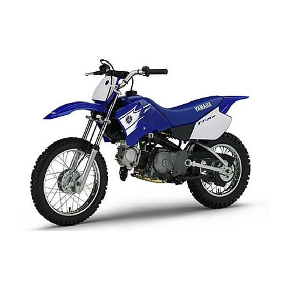
- Page 4 INTRODUCTION Congratulations on your purchase of a Yamaha TT-R90R. This model is the culmina- tion of Yamaha’s vast experience in the pro- duction of pacesetting racing machines. It represents the highest grade of craftsmanship and reliability that have made Yamaha a leader.
-
Page 6: Important Notice
IMPORTANT NOTICE This machine is designed for off-road use only by young operators under adult instruction and supervision. It is illegal for this machine to be operated on any public street, road, or high- way. Off-road use on public lands may be illegal. Please check local regulations before riding. - Page 7 4. When transporting the machine in another vehicle, be sure is kept upright and that the fuel cock is turned to the “OFF”. If it should lean over, gasoline may leak out of the car- buretor or fuel tank. 5. Never start your engine or let it run for any length of time in a closed area.
- Page 8 SAFETY INFORMATION 1. Don’t ride it on the street. 2. Don’t run the engine inside a building. 3. This is a one-seater motorbike. Don’t give any person a ride. 4. Let’s learn how to ride properly. Ask your parents for any question. 5.
- Page 9 6. When going for riding, be sure to be with your family. Never go alone. 7. Before riding the machine, ask your par- ents to check the machine very carefully. 8. Don’t touch the areas shown, or you’ll get burnt in the hand. 9.
- Page 10 EC080000 HOW TO USE THIS MANUAL EC081000 PARTICULARLY IMPORTANT INFORMATION The Safety Alert Symbol means ATTENTION! BECOME ALERT! YOUR SAFETY INVOLVED! WARNING Failure to follow WARNING instructions could result in severe injury or death to the machine operator, a bystander, or a person inspecting or repairing the machine.
- Page 11 EC083000 MANUAL FORMAT All of the procedures in this manual are organized in a sequential, step-by-step format. The informa- tion has been complied to provide the mechanic with an easy to read, handy reference that contains comprehensive explanations of all disassembly, repair, assembly, and inspection operations. In this revised format, the condition of a faulty component will precede an arrow symbol and the course of action required will follow the symbol, e.g.
- Page 12 ILLUSTRATED SYMBOLS (Refer to the illustration) SPEC Illustrated symbols 1 to 6 are designed as INFO thumb tabs to indicate the chapter’s number and content. 1 General information INSP 2 Specifications 3 Regular inspection and adjustments 4 Engine 5 Chassis 6 Electrical –...
- Page 13 INDEX GENERAL INFORMATION INFO SPECIFICATIONS SPEC REGULAR INSPECTION AND ADJUSTMENTS INSP ENGINE CHASSIS CHAS – ELECTRICAL ELEC...
-
Page 14: Table Of Contents
CONTENTS CHAPTER 1 GENERAL INFORMATION DESCRIPTION .......... 1-1 MACHINE IDENTIFICATION ....1-2 IMPORTANT INFORMATION ....1-3 CHECKING OF CONNECTION ....1-5 SPECIAL TOOLS ........1-6 CONTROL FUNCTIONS ......1-9 FUEL ............1-11 STARTING AND OPERATION ....1-12 CHAPTER 2 SPECIFICATIONS GENERAL SPECIFICATIONS .... - Page 15 CHAPTER 4 ENGINE CARBURETOR ......... 4-1 CYLINDER HEAD ........4-8 CAMSHAFT AND ROCKER ARMS ..4-13 VALVES AND VALVE SPRINGS ... 4-16 CYLINDER AND PISTON ....... 4-21 CLUTCH ..........4-27 KICK AXLE ..........4-33 SHIFT SHAFT ......... 4-34 OIL PUMP ..........4-36 CDI MAGNETO ........
-
Page 16: General Information
DESCRIPTION INFO EC100000 GENERAL INFORMATION EC110000 DESCRIPTION 1 “ENGINE STOP” button 2 Front brake lever 3 Throttle grip 4 Fuel tank cap 5 Kick starter 6 Fuel tank 7 Air cleaner 8 Rear brake pedal 9 Fuel cock 0 Starter lever (choke) A Drive chain B Shift pedal C Front fork... -
Page 17: Machine Identification
There are two significant reasons for knowing the serial number of your machine: 1. When ordering parts, you can give the number to your Yamaha dealer for posi- tive identification of the model you own. 2. If your machine is stolen, the authorities will need the number to search for and identify your machine. -
Page 18: Important Information
IMPORTANT INFORMATION INFO EC130000 IMPORTANT INFORMATION EC131002 PREPARATION FOR REMOVAL AND DISASSEMBLY 1. Remove all dirt, mud, dust, and foreign material before removal and disassem- bly. When washing the machine with high pressured water, cover the parts as fol- lows. Silencer exhaust port 2. - Page 19 IMPORTANT INFORMATION INFO EC132000 ALL REPLACEMENT PARTS 1. We recommend to use Yamaha genuine parts for all replacements. Use oil and/or grease recommended by Yamaha for assembly and adjustment. EC133000 GASKETS, OIL SEALS AND O-RINGS 1. All gaskets, oil seals, and O-rings should be replaced when an engine is over- hauled.
-
Page 20: Checking Of Connection
IMPORTANT INFORMATION/ CHECKING OF CONNECTION INFO EC136000 CIRCLIPS 1. All circlips should be inspected carefully before reassembly. Always replace pis- ton pin clips after one use. Replace dis- torted circlips. When installing a circlip 1, make sure that the sharp-edged cor- ner 2 is positioned opposite to the thrust 3 it receives. -
Page 21: Special Tools
SPECIAL TOOLS INFO SPECIAL TOOLS The proper special tools are necessary for complete and accurate tune-up and assembly. Using the correct special tool will help prevent damage caused by the use of improper tools or improvised techniques. The shape and part number used for the special tool differ by country, so two types are provided. - Page 22 SPECIAL TOOLS INFO Part number Tool name/How to use Illustration YM-1312-A, 90890-01312 Fuel level gauge YM-1312-A 90890-01312 This gauge is used to measure the fuel level in the float chamber. YM-1326, 90890-01326 T-handle YM-1326 90890-01326 This tool is used for holding the damper rod holder when removing or installing the damper rod holder.
- Page 23 Tool name/How to use Illustration YU-33270-B, 90890-01362 Flywheel puller YU-33270-B 90890-01362 This tool is used to remove the rotor. ACC-QUICK-GS-KT Quick gasket ® ACC-QUICK-GS-KT 90890-85505 90890-85505 YAMAHA Bond No. 1215 This sealant (Bond) is used for crankcase mating surface, etc. 1 - 8...
-
Page 24: Control Functions
CONTROL FUNCTIONS INFO EC150000 CONTROL FUNCTIONS “ENGINE STOP” SWITCH Make sure that the engine stop switch 1 is positioned to “ ”. The engine stop switch has been equipped to ensure safety in an emer- gency such when the machine is up set or trouble takes place in the throttle system. - Page 25 CONTROL FUNCTIONS INFO EC156000 FRONT BRAKE LEVER The front brake lever 1 is located on the right handlebar. Pull it toward the handlebar to acti- vate the front brake. EC157000 REAR BRAKE PEDAL The rear brake pedal 1 is located on the right side of the machine.
-
Page 26: Fuel
CONTROL FUNCTIONS/FUEL INFO FUEL TANK CAP Remove the fuel tank cap 1 by turning counter-clockwise. WARNING Do not overfill the fuel tank. Avoid spilling fuel on the hot engine. FUEL Use regular gasoline. Always use fresh, name brand gasoline. WARNING Do not overfill the fuel tank. -
Page 27: Starting And Operation
STARTING AND OPERATION INFO STARTING AND OPERATION WARMING UP To get maximum engine life, always “warm-up” the engine before starting off. Never acceler- CAUTION: ate hard with a cold engine! To see whether or Prior to operating the machine, perform not the engine is warm, see if it responds to steps listed in pre-operation check list. -
Page 28: Specifications
SPEC GENERAL SPECIFICATIONS EC200000 SPECIFICATIONS EC211000 GENERAL SPECIFICATIONS Model name: TT-R90R (USA, CDN, AUS, NZ) TT-R90 (Europe, ZA) Model code number: 5HNB (USA) 5HNC (Europe, AUS, NZ, ZA) 5HND (CDN) Dimensions: Overall length 1,525 mm (57.0 in) Overall width 605 mm (23.8 in) Overall height 865 mm (34.1 in) - Page 29 SPEC GENERAL SPECIFICATIONS Oil capacity: Engine oil Periodic oil change 0.8 L (0.70 Imp qt, 0.85 US qt) Total amount 1.0 L (0.88 Imp qt, 1.06 US qt) Air filter: Wet type element Fuel: Type Unleaded gasoline only (USA, AUS and NZ) Regular unleaded gasoline only (CDN, Europe) Regular gasoline (ZA) Tank capacity...
- Page 30 SPEC GENERAL SPECIFICATIONS Brake: Front brake type Drum brake Operation Right hand operation Rear brake type Drum brake Operation Right foot operation Suspension: Front suspension Telescopic fork Rear suspension Swingarm (monocross suspension) Shock absorber: Front shock absorber Coil spring/oil damper Rear shock absorber Coil spring/gas, oil damper Wheel travel:...
-
Page 31: Maintenance Specifications
SPEC MAINTENANCE SPECIFICATIONS MAINTENANCE SPECIFICATIONS ENGINE Item Standard Limit Cylinder head: Warp limit ---- 0.03 mm (0.0012 in) Cylinder: Bore size 47.000 ~ 47.005 mm 47.05 mm (1.8504 ~ 1.8506 in) (1.8524 in) Out of round limit ---- 0.05 mm (0.0020 in) Camshaft: Drive method... - Page 32 SPEC MAINTENANCE SPECIFICATIONS Item Standard Limit Cam chain: Cam chain type/No. of links 92RH2005-84M/84 ---- Cam chain adjustment method Automatic ---- Rocker arm/rocker arm shaft: Shaft outside diameter 9.981 ~ 9.991 mm 9.95 mm (0.3930 ~ 0.3933 in) (0.3917 in) Rocker arm inside diameter 10.000 ~ 10.015 mm 10.03 mm...
- Page 33 SPEC MAINTENANCE SPECIFICATIONS Item Standard Limit Stem runout limit ---- 0.02 mm (0.0008 in) Valve seat width 0.9 ~ 1.1 mm 1.6 mm (0.0354 ~ 0.0433 in) (0.0630 in) 0.9 ~ 1.1 mm 1.6 mm (0.0354 ~ 0.0433 in) (0.0630 in) Valve spring: Free length 28.32 mm (1.11 in)
- Page 34 SPEC MAINTENANCE SPECIFICATIONS Item Standard Limit Piston: Piston to cylinder clearance 0.025 ~ 0.045 mm 0.15 mm (0.0010 ~ 0.0018 in) (0.0059 in) Piston size “D” 46.960 ~ 46.975 mm ---- (1.8488 ~ 1.8494 in) Piston over size (2nd) 47.5 mm (1.8701 in) ---- (4th) 48.0 mm (1.8898 in)
- Page 35 SPEC MAINTENANCE SPECIFICATIONS Item Standard Limit Crankshaft: Crank width “A” 42.95 ~ 43.00 mm ---- (1.691 ~ 1.693 in) Runout limit C ---- 0.03 mm (0.0012 in) Big end side clearance “D” 0.10 ~ 0.40 mm 0.50 mm (0.0039 ~ 0.0157 in) (0.02 in) Big end radial clearance “E”...
- Page 36 SPEC MAINTENANCE SPECIFICATIONS Item Standard Limit Lubrication system: Oil filter type Wire mesh type ---- Oil pump type Trochoid type ---- Tip clearance “A” or “B” 0.15 mm 0.2 mm (0.0059 in) (0.0079 in) Side clearance 0.13 ~ 0.18 mm 0.23 mm (0.0051 ~ 0.0071 in) (0.0091 in)
- Page 37 SPEC MAINTENANCE SPECIFICATIONS Tightening torque Part to be tightened Thread size Q’ty m•kg ft•lb M8 × 1.25 Cylinder head nut M6 × 1.0 Cylinder head bolt M10 × 1.0 Spark plug M6 × 1.0 Camshaft sprocket cover bolt M45 × 1.5 Tappet cover M6 ×...
- Page 38 SPEC MAINTENANCE SPECIFICATIONS CHASSIS Item Standard Limit Steering system: Steering bearing type Angular bearing ---- Front suspension: Front fork travel 110 mm (4.33 in) ---- Fork spring free length 425.1 mm (16.74 in) 417 mm (16.4 in) Fork spring fitting length 415.1 mm (16.34 in) ---- Spring rate, STD...
- Page 39 SPEC MAINTENANCE SPECIFICATIONS Item Standard Limit Drum brake: Front drum brake type Leading, trailing ---- Rear drum brake type Leading, trailing ---- Front drum inside diameter 95 mm (3.74 in) 96 mm (3.78 in) Rear drum inside diameter 110 mm (4.33 in) 111 mm (4.37 in) Front lining thickness 3 mm (0.12 in)
- Page 40 SPEC MAINTENANCE SPECIFICATIONS Tightening torque Part to be tightened Thread size Q’ty m•kg ft•lb Engine mounting: M8 × 1.25 Engine and frame (front-upper) M8 × 1.25 Engine and frame (rear-upper) M10 × 1.25 Engine and frame (rear-lower) M11 × 1.25 Starter cable and frame M10 ×...
- Page 41 EC212300 ELECTRICAL Item Standard Limit CDI: Magneto-model/manufacturer F5HN 00/YAMAHA ---- 688 ~ 1,032 Ω at 20 ˚C (68 ˚F) Source coil resistance (color) ---- (Brown – Green) 248 ~ 372 Ω at 20 ˚C (68 ˚F) Pickup coil resistance (color) ---- (Red –...
-
Page 42: General Torque Specifications
GENERAL TORQUE SPECIFICATIONS/ SPEC DEFINITION OF UNITS EC220001 GENERAL TORQUE SPECIFICATIONS This chart specifies torque for standard fasten- ers with standard I.S.O. pitch threads. Torque specifications for special components or assemblies are included in the applicable sec- tions of this book. To avoid warpage, tighten multi-fastener assemblies in a crisscross fash- ion, in progressive stages, until full torque is reached. -
Page 43: Cable Routing Diagram
SPEC CABLE ROUTING DIAGRAM CABLE ROUTING DIAGRAM 1 Crankcase breather hose A Cable holder 2 Wire harness B Fuel tank breather hose 3 CDI magneto lead C Brake cable 4 Starter cable Å After fastening the starter cable, CDI magneto lead, wire harness and 5 Carburetor heating lead 6 Engine stop switch lead thermo switch lead, cut off any excess from the plastic locking tie end. - Page 44 SPEC CABLE ROUTING DIAGRAM 1 Cable guide B CDI unit lead 2 Brake cable C CDI unit 3 Throttle cable D Rectifier/regulator lead 4 Fuel tank breather hose E Rectifier/regulator 5 Engine stop switch lead F Crankcase breather hose 6 Air vent hose G Carburetor breather hose 7 Air intake duct H Spark plug lead...
- Page 45 SPEC CABLE ROUTING DIAGRAM Å Pass the fuel tank breather hose through the Ì Pass the CDI unit lead through the lead guide. cable guide. ı Pass the throttle cable and engine stop switch lead through the cable guide. Ç Pass the air vent hose through the hose guide. Î...
-
Page 46: Regular Inspection And Adjustments
If you are a doubt as to what intervals to follow in maintaining and lubricating your machine, consult your Yamaha dealer. PERIODIC MAINTENANCE AND LUBRICATION... -
Page 47: Pre-Operation Inspection And Maintenance
INSP PRE-OPERATION INSPECTION AND MAINTENANCE Initial Every Dealer Item Checks and maintenance jobs 10 hours 60 hours 120 hours Note (1 month) (6 months) (12 months) Make sure that all nuts, bolts and screws are Chassis fasteners properly tightened. Tighten if necessary. Check operation. -
Page 48: Engine
ENGINE/THROTTLE CABLE ADJUSTMENT/ INSP AIR FILTER CLEANING EC350000 ENGINE THROTTLE CABLE ADJUSTMENT 1. Check: Throttle grip free play a Out of specification → Adjust. Throttle grip free play a: 3 ~ 5 mm (0.12 ~ 0.20 in) 2. Adjust: Throttle grip free play Throttle grip free play adjustment steps: NOTE: Before adjusting the throttle cable free play,... - Page 49 INSP AIR FILTER CLEANING 1. Install: Air scoop (right) 1 2. Install: Air filter case cover 1 3. Clean: Air filter element Clean them with solvent. NOTE: After cleaning, remove the remaining solvent by squeezing the element. CAUTION: Do not twist the element when squeezing the element.
-
Page 50: Engine Oil Level Inspection
INSP ENGINE OIL LEVEL INSPECTION ENGINE OIL LEVEL INSPECTION 1. Start the engine, warm it up for several minutes and wait for five minutes. 2. Place the machine on a level place and hold it up on upright position by placing the suitable stand under the engine. - Page 51 INSP ENGINE OIL REPLACEMENT (Except for USA and CDN) Recommended oil: Refer to the following chart for selection of oils which are suited to the atmospheric temperatures. Recommended engine oil classi- fication: API STANDARD: API “SE/SF” or higher grade (Designed primarily for motor- cycles) CAUTION: Do not add any chemical additives or use...
- Page 52 INSP PILOT AIR SCREW ADJUSTMENT 5. Install: Gasket Drain bolt 20 Nm (2.0 m · kg, 14 ft · lb) 6. Fill: Crankcase Oil quantity: Periodic oil change: 0.8 L (0.70 Imp qt, 0.85 US qt) 7. Install: Dipstick 8. Inspect: Engine (for oil leaks) Oil level Refer to “ENGINE OIL LEVEL INSPEC-...
- Page 53 IDLE SPEED ADJUSTMENT/ INSP VALVE CLEARANCE ADJUSTMENT IDLE SPEED ADJUSTMENT 1. Start the engine and thoroughly warm it 2. Attach: Inductive tachometer To spark plug lead. 3. Adjust: Idle speed Adjustment steps: Adjust the pilot screw. Refer to “PILOT AIR SCREW ADJUST- MENT”...
- Page 54 INSP VALVE CLEARANCE ADJUSTMENT 4. Check: Valve clearance Out of specification → Adjust. Valve clearance (cold): Intake valve: 0.05 ~ 0.09 mm (0.0020 ~ 0.0035 in) Exhaust valve: 0.08 ~ 0.12 mm (0.031 ~ 0.047 in) Checking steps: Turn the crankshaft counterclockwise with a wrench.
- Page 55 INSP SPARK ARRESTER CLEANING (For USA) 6. Install: Tappet cover (intake side) 1 18 Nm (1.8 m · kg, 13 ft · lb) O-ring 2 NOTE: Apply the lithium soap base grease on the O-ring. 7. Install: Tappet cover (exhaust side) 18 Nm (1.8 m ·...
-
Page 56: Chassis
CHASSIS/FRONT BRAKE ADJUSTMENT/ INSP REAR BRAKE ADJUSTMENT CHASSIS FRONT BRAKE ADJUSTMENT 1. Check: Brake lever free play a Out of specification → Adjust. Free play (brake lever): 10 ~ 20 mm (0.39 ~ 0.79 in) (at brake lever end) 2. Adjust: Brake lever free play Adjustment steps: Loosen the locknuts 1. - Page 57 INSP DRIVE CHAIN SLACK ADJUSTMENT DRIVE CHAIN SLACK ADJUSTMENT 1. Elevate the rear wheel by placing the suitable stand under the engine. 2. Check: Drive chain slack a In the center between the drive axle and rear wheel axle. Out of specification → Adjust. Drive chain slack: 40 ~ 53 mm (1.6 ~ 2.1 in) NOTE:...
- Page 58 INSP FRONT FORK INSPECTION/REAR SHOCK ABSORBER INSPECTION/ REAR SHOCK ABSORBER SPRING PRELOAD ADJUSTMENT Tighten the wheel axle nut while pushing down the drive chain. Axle nut: 60 Nm (6.0 m • kg, 43 ft • lb) EC36C000 FRONT FORK INSPECTION 1.
- Page 59 INSP TIRE PRESSURE CHECK 4. To stiffen the spring preload, install the circlip 1 into the groove a. To soften the spring preload, install the circlip into the groove b. NOTE: Do not spread the circlip too much. Standard installation position: Groove b 5.
- Page 60 INSP SPOKES INSPECTION AND TIGHTENING/WHEEL INSPECTION/ STEERING HEAD INSPECTION AND ADJUSTMENT SPOKES INSPECTION AND TIGHTENING 1. Inspect: Spokes 1 Bend/damage → Replace. Loose spoke → Retighten. 2. Tighten: Spokes 2 Nm (0.2 m · kg, 1.4 ft · lb) NOTE: Be sure to retighten these spokes before and after break-in.
- Page 61 INSP STEERING HEAD INSPECTION AND ADJUSTMENT 3. Check: Steering smooth action Turn the handlebar lock to lock. Unsmooth action → Adjust steering ring nut. 4. Adjust: Steering ring nut Steering ring nut adjustment steps: Remove the front fender 1. Remove the handlebar and handle crown. Loosen the ring nut 2 using the ring nut wrench 3.
- Page 62 INSP STEERING HEAD INSPECTION AND ADJUSTMENT CAUTION: Install the handlebar holder with its groove a facing outward, and tighten the bolts so that the gaps b are equal. Steering stem bolt: 40 Nm (4.0 m • kg, 2.9 ft • lb) Front fork cap bolt: 40 Nm (4.0 m •...
- Page 63 INSP LUBRICATION Å Use Yamaha cable lube or equivalent on these LUBRICATION areas. To ensure smooth operation of all compo- ı Use SAE 10W-30 motor oil or suitable chain nents, lubricate your machine during setup, lubricants. after break-in, and after every race.
-
Page 64: Electrical
INSP ELECTRICAL/SPARK PLUG INSPECTION EC370000 ELECTRICAL EC371001 SPARK PLUG INSPECTION 1. Remove: Spark plug 2. Inspect: Electrode 1 Wear/damage → Replace. Insulator color 2 Normal condition is a medium to light tan color. Distinctly different color → Check the engine condition. NOTE: When the engine runs for many hours at low speeds, the spark plug insulator will become... -
Page 65: Carburetor
CARBURETOR ENGINE CARBURETOR Extent of removal: 1 Carburetor removal Extent of removal Order Part name Q’ty Remarks CARBURETOR REMOVAL Preparation for removal Fuel tank Clamp (air filter joint) Loosen the screw (air filter joint). Carburetor heater lead Air vent hose Fuel hose Bolt Carburetor assembly... - Page 66 CARBURETOR EC468000 CARBURETOR DISASSEMBLY Extent of removal: 1 Carburetor disassembly Extent of removal Order Part name Q’ty Remarks CARBURETOR DISASSEMBLY Throttle valve Throttle cable Spring Gasket Carburetor top cover Jet needle stopper Jet needle assembly Starter plunger assembly Starter cable Float chamber 4 - 2...
- Page 67 CARBURETOR Extent of removal Order Part name Q’ty Remarks Float pin Float Needle valve Main jet Pilot jet Needle jet Throttle stop screw assembly Pilot air screw assembly Carburetor heater 4 - 3...
- Page 68 CARBURETOR EC464000 INSPECTION Carburetor 1. Inspect: Carburetor body Contamination → Clean. NOTE: Use a petroleum based solvent for cleaning. Blow out all passages and jets with com- pressed air. Never use a wire. 2. Inspect: Main jet 1 Pilot jet 2 Needle jet 3 Damage →...
- Page 69 CARBURETOR EC464401 Jet needle 1. Inspect: Jet needle 1 Bends/wear → Replace. Clip groove Free play exists/wear → Replace. Clip position Standard clip position: No.2 Groove Float height 1. Measure: Float height a Out of specification → Adjust. Float height: 15.5 ~ 16.5 mm (0.61 ~ 0.65 in) Measurement and adjustment steps: Hold the carburetor in an upside down...
- Page 70 CARBURETOR EC464600 Float 1. Inspect: Float 1 Damage → Replace. ASSEMBLY AND INSTALLATION Carburetor 1. Install: Pilot air screw 1 Note the following installation points: Screw in the pilot air screw until it is lightly seated. Back out it by the specified number of turns.
- Page 71 CARBURETOR 1. Measure: Fuel level a Use a fuel level gauge 1. Out of specification → Adjust. Fuel level gauge: YM-1312-A/90890-01312 Fuel level: 2 ~ 3 mm (0.08 ~ 0.12 in) below the float chamber line 4 - 7...
-
Page 72: Cylinder Head
CYLINDER HEAD CYLINDER HEAD Extent of removal: 1 Cylinder head removal Extent of removal Order Part name Q’ty Remarks CYLINDER HEAD REMOVAL Preparation for removal Seat, fuel tank and rear fender Exhaust pipe Carburetor Refer to “CARBURETOR” section. Air filter case and starter lever Plug cap/spark plug Crankshaft end cover/O-ring Timing plug/O-ring... - Page 73 CYLINDER HEAD Extent of removal Order Part name Q’ty Remarks Camshaft sprocket Timing chain Refer to “REMOVAL POINTS”. Cylinder head Gasket Dowel pin 4 - 9...
- Page 74 CYLINDER HEAD REMOVAL POINTS Cylinder head 1. Align: “I” mark (with stationary pointer) Checking steps: Turn the crankshaft counterclockwise with a wrench. Align the “I” mark a on the rotor with the stationary pointer b on the crankcase cover. When the “I” mark is aligned with the stationary pointer, the piston is at the Top Dead Center (T.D.C.).
- Page 75 CYLINDER HEAD 4. Remove: Cylinder head NOTE: Loosen the bolts and nuts in their proper loosening sequence. Start by loosening each bolt and nut 1/2 turn until all are loose. ASSEMBLY AND INSTALLATION 1. Install: Cylinder head 2. Tighten: Nuts 22 Nm (2.2 m ·...
- Page 76 CYLINDER HEAD CAUTION: Do not turn the crankshaft during instal- lation of the camshaft. Damage or improper valve timing will result. Remove the safety wire from the timing chain. 4. Install: Washer Bolt 1 20 Nm (2.0 m · kg, 14 ft · lb) NOTE: Install the bolt 1 while holding the rotor nut with a wrench.
-
Page 77: Camshaft And Rocker Arms
CAMSHAFT AND ROCKER ARMS CAMSHAFT AND ROCKER ARMS Extent of removal: 1 Rocker arm 2 Camshaft removal Extent of removal Order Part name Q’ty Remarks CAMSHAFT AND ROCKER ARMS Preparation for removal Cylinder head Refer to “CYLINDER HEAD” section. Rocker arm shaft (intake) Use special tool. - Page 78 CAMSHAFT AND ROCKER ARMS REMOVAL POINTS Rocker arm shaft 1. Remove: Rocker arm shafts NOTE: Use a slide hammer bolt 1 and weight 2 to slide out the rocker arm shafts. Slide hammer set: YU-1083-A Slide hammer bolt: 90890-01085 Weight: 90890-01084 INSPECTION Camshaft...
- Page 79 CAMSHAFT AND ROCKER ARMS 3. Apply: Molybdenum disulfide oil (onto the rocker arm and rocker arm shaft) 4. Install: Rocker arm 1 Rocker arm shaft 2 4 - 15...
-
Page 80: Valves And Valve Springs
VALVES AND VALVE SPRINGS VALVES AND VALVE SPRINGS Extent of removal: 1 Valves removal Extent of removal Order Part name Q’ty Remarks VALVES AND VALVE SPRINGS REMOVAL Preparation for removal Cylinder head Refer to “CYLINDER HEAD” section. Rocker arm and camshaft Refer to “CAMSHAFT AND ROCKER ARMS”... - Page 81 VALVES AND VALVE SPRINGS REMOVAL POINTS Valve removal 1. Remove: Valve cotters 1 NOTE: Attach a valve spring compressor 2 between the valve spring retainer and the cylinder head to remove the valve cotters. Valve spring compressor: YM-4019/90890-04019 INSPECTION Valve 1.
- Page 82 VALVES AND VALVE SPRINGS Valve spring 1. Measure: Valve spring free length a Out of specification → Replace. Free length (valve spring): Intake: 28.32 mm (1.11 in) <Limit>: 26.9 mm (1.06 in) Exhaust: 28.32 mm (1.11 in) <Limit>: 26.9 mm (1.06 in) 2.
- Page 83 VALVES AND VALVE SPRINGS 2. Lap: Valve face Valve seat NOTE: After refacing the valve seat or replacing the valve and valve guide, the valve seat and valve face should be lapped. Lapping steps: Apply a coarse lapping compound to the valve face.
- Page 84 VALVES AND VALVE SPRINGS ASSEMBLY AND INSTALLATION 1. Apply: Molybdenum disulfide oil (onto the valve stem and valve stem seal) 2. Install: Valve stem seats Valves Valve springs Valve spring retainers NOTE: Make sure that each valve is installed in its original place, also referring to the embossed mark as follows.
-
Page 85: Cylinder And Piston
CYLINDER AND PISTON CYLINDER AND PISTON Extent of removal: 1 Cylinder removal 2 Piston removal Extent of removal Order Part name Q’ty Remarks CYLINDER AND PISTON REMOVAL Preparation for removal Cylinder head Refer to “CYLINDER HEAD” section. Timing chain guide (exhaust) Cylinder Dowel pin Gasket... - Page 86 CYLINDER AND PISTON REMOVAL POINTS Piston 1. Remove: Piston pin clips 1 Piston pin 2 Piston 3 NOTE: Before removing the piston pin clip, cover the crankcase opening with a clean towel or rag to prevent the clip from falling into the crank- case cavity.
- Page 87 CYLINDER AND PISTON 47.000 ~ 47.005 mm Cylinder bore “C” (1.8504 ~ 1.8506 in) Taper limit “T” 0.05 mm (0.002 in) Out of round “R” 0.05 mm (0.002 in) “C” = Maximum D “T” = (Maximum D or D – (Maximum D or D “R”...
- Page 88 CYLINDER AND PISTON Piston ring 1. Measure: Ring side clearance Use a feeler gauge. Out of specification → Replace the pis- ton and rings as a set. NOTE: Clean carbon from the piston ring grooves and rings before measuring the side clearance. Side clearance Standard Limit...
- Page 89 CYLINDER AND PISTON Piston pin 1. Inspect: Piston pin Blue discoloration/grooves → Replace, then inspect the lubrication system. 2. Measure: Piston pin outside diameter Piston pin bore inside diameter Measurement steps: Measure the piston pin outside diameter If out of specification, replace the piston Outside diameter (piston pin): 12.996 ~ 13.000 mm (0.5117 ~ 0.5118 in)
- Page 90 CYLINDER AND PISTON 2. Position: Top ring 2nd ring Oil ring Offset the piston ring end gaps as shown. a Top ring end b Oil ring end (lower) c Oil ring end (upper) d 2nd ring end 3. Install: Piston 1 Piston pin 2 Piston pin clips 3 NOTE:...
-
Page 91: Clutch
CLUTCH CLUTCH CRANKCASE COVER (LEFT AND RIGHT) Extent of removal: 1 Crankcase cover (left) removal 2 Crankcase cover (right) removal Extent of removal Order Part name Q’ty Remarks CRANKCASE COVER (LEFT AND RIGHT) REMOVAL Preparation for removal Drain the engine oil. Refer to “ENGINE OIL REPLACEMENT”... - Page 92 CLUTCH CLUTCH Extent of removal: 1 Friction plate and clutch plate removal 2 Clutch housing removal 3 Primary clutch removal Extent of removal Order Part name Q’ty Remarks CLUTCH REMOVAL Bolt/clutch spring Pressure plate Washer Push rod #1 Friction plate Clutch plate Push rod #2 Clutch boss nut...
- Page 93 CLUTCH Extent of removal Order Part name Q’ty Remarks Spacer Spacer Primary clutch nut Use special tool. Refer to “REMOVAL POINTS”. Washer Spacer Primary clutch housing Primary clutch boss Clutch carrier One-way clutch assembly Washer 4 - 29...
- Page 94 CLUTCH REMOVAL POINTS Clutch boss 1. Remove: Clutch boss nut 1 Lock washer 2 Clutch boss NOTE: Straighten the lock washer tab and use the clutch holding tool 3 to hold the clutch boss. Å ı Clutch holding tool: YM-91042/90890-04086 Å...
- Page 95 CLUTCH EC484600 Clutch plate 1. Measure: Clutch plate warpage Out of specification → Replace clutch plate as a set. Use a surface plate 1 and thickness gauge 2. Warp limit: 0.2 mm (0.008 in) EC484400 Clutch spring 1. Measure: Clutch spring free length a Out of specification →...
- Page 96 CLUTCH ASSEMBLY AND INSTALLATION Primary clutch 1. Install: Washer 1 Nut (primary clutch) 2 50 Nm (5.0 m · kg, 36 ft · lb) NOTE: Tighten the nut while holding the magneto rotor with the sheave holder 3. Sheave holder: YS-1880-A/90890-01701 Clutch 1.
-
Page 97: Kick Axle
KICK AXLE KICK AXLE Extent of removal: 1 Kick axle removal 2 Kick axle disassembly Extent of removal Order Part name Q’ty Remarks KICK AXLE REMOVAL AND DISASSEMBLY Preparation for removal Crankcase cover (right) Refer to “CLUTCH” section. Kick axle assembly Circlip Spring cover Torsion spring... -
Page 98: Shift Shaft
SHIFT SHAFT SHIFT SHAFT Extent of removal: 1 Shift shaft removal Extent of removal Order Part name Q’ty Remarks SHIFT SHAFT REMOVAL Preparation for removal Clutch housing and clutch carrier Refer to “CLUTCH” section. Shift fork guide bar Shift arm 3 Plate washer Compression spring Shift guide... - Page 99 SHIFT SHAFT Extent of removal Order Part name Q’ty Remarks Stopper lever Torsion spring Circlip Plate washer Torsion spring Shift lever 4 - 35...
-
Page 100: Oil Pump
OIL PUMP OIL PUMP Extent of removal: 1 Oil pump removal 2 Oil strainer removal 3 Oil pump disassembly Extent of removal Order Part name Q’ty Remarks OIL PUMP REMOVAL AND DIS- ASSEMBLY Preparation for removal Clutch housing and clutch carrier Refer to “CLUTCH”... - Page 101 OIL PUMP Extent of removal Order Part name Q’ty Remarks Oil pump cover Dowel pin Oil pump drive shaft Inner rotor Outer rotor Rotor housing 4 - 37...
- Page 102 OIL PUMP INSPECTION Oil pump 1. Measure: Tip clearance a (between the inner rotor 1 and the outer rotor 2) Side clearance b (between the outer rotor 2 and the rotor housing 3) Out of specification → Replace the oil pump assembly.
-
Page 103: Cdi Magneto
CDI MAGNETO CDI MAGNETO Extent of removal: 1 Pickup coil/stator assembly removal 2 Rotor removal Extent of removal Order Part name Q’ty Remarks CDI MAGNETO AND STATOR REMOVAL Preparation for removal Fuel tank Crankcase cover (left) Refer to “CLUTCH” section. CDI magneto coupler Pickup coil/stator assembly Rotor nut... - Page 104 CDI MAGNETO REMOVAL POINTS Rotor 1. Remove: Rotor nut 1 Washer 2 NOTE: Loosen the rotor nut while holding the rotor with sheave holder 3. Do not allow the sheave holder to touch the projection on the rotor. Sheave holder: YS-1880-A/90890-01701 2.
-
Page 105: Crankcase And Crankshaft
CRANKCASE AND CRANKSHAFT CRANKCASE AND CRANKSHAFT Extent of removal Order Part name Q’ty Remarks CRANKCASE SEPARATION AND CRANKSHAFT REMOVAL Preparation for removal Seat, fuel tank and rear fender Exhaust pipe Air filter case Carburetor Refer to “CARBURETOR” section. Drain the engine oil Refer to “ENGINE OIL REPLACEMENT”... - Page 106 CRANKCASE AND CRANKSHAFT Extent of removal: 1 Timing chain removal 2 Crankcase separation 3 Crankshaft removal Extent of removal Order Part name Q’ty Remarks Shift shaft Refer to “SHIFT SHAFT” section. Oil pump and oil strainer Refer to “OIL PUMP” section. Rotor Refer to “CDI MAGNETO”...
- Page 107 1. Apply: Sealant On the crankcase (left). ® Quick gasket ACC-QUICK-GS-KT YAMAHA Bond No. 1215: 90890-85505 NOTE: Clean the contacting surface of crankcase (left and right) before applying the sealant. DO NOT ALLOW any sealant to come in contact with the oil gallery a.
-
Page 108: Shift Fork, Shift Cam And Transmission
SHIFT FORK, SHIFT CAM AND TRANSMISSION SHIFT FORK, SHIFT CAM AND TRANSMISSION Extent of removal: 1 Shift fork, shift cam, main axle and drive axle removal 2 Main axle disassembly 3 Drive axle disassembly Extent of removal Order Part name Q’ty Remarks SHIFT FORK, SHIFT CAM... - Page 109 SHIFT FORK, SHIFT CAM AND TRANSMISSION Extent of removal Order Part name Q’ty Remarks 3th pinion gear Main axle Circlip Washer Collar 1st wheel gear 3rd wheel gear Circlip Washer 2nd wheel gear Drive axle 4 - 45...
- Page 110 SHIFT FORK, SHIFT CAM AND TRANSMISSION EC4H3000 REMOVAL POINTS Shift fork, shift cam and transmission 1. Remove: Shift forks Shift cam Drive axle assembly Main axle assembly NOTE: Tap lightly on the transmission drive axle and shift cam with a soft hammer to remove. Remove assembly carefully.
-
Page 111: Chassis
CHAS FRONT WHEEL AND REAR WHEEL EC500000 CHASSIS FRONT WHEEL AND REAR WHEEL FRONT WHEEL AND FRONT BRAKE Extent of removal: 1 Front wheel removal 2 Wheel bearing removal 3 Brake shoe plate assembly removal and disassembly Extent of removal Order Part name Q’ty... - Page 112 CHAS FRONT WHEEL AND REAR WHEEL Extent of removal Order Part name Q’ty Remarks Brake shoe Brake camshaft lever Brake camshaft 5 - 2...
- Page 113 CHAS FRONT WHEEL AND REAR WHEEL REAR WHEEL AND REAR BRAKE Extent of removal: 1 Rear wheel removal 2 Wheel bearing removal 3 Brake shoe plate assembly removal and disassembly Extent of removal Order Part name Q’ty Remarks REAR WHEEL REMOVAL WARNING Preparation for removal Hold the machine by placing the...
- Page 114 CHAS FRONT WHEEL AND REAR WHEEL Extent of removal Order Part name Q’ty Remarks Collar (left) Wheel drive hub assembly Bearing Refer to “REMOVAL POINTS”. Brake shoe Brake camshaft lever Brake camshaft 5 - 4...
- Page 115 CHAS FRONT WHEEL AND REAR WHEEL EC593000 REMOVAL POINTS EC513201 Wheel bearing (if necessary) 1. Remove: Bearing 1 NOTE: Remove the bearing using a general bearing puller 2. EC594000 INSPECTION EC514100 Wheel 1. Measure: Wheel runout Out of limit → Repair/replace. Wheel runout limit: Radial 1: 2.0 mm (0.08 in) Lateral 2: 2.0 mm (0.08 in)
-
Page 116: Front Fork
CHAS FRONT FORK EC550000 FRONT FORK Extent of removal: 1 Front fork removal Extent of removal Order Part name Q’ty Remarks FRONT FORK REMOVAL WARNING Preparation for removal Hold the machine by placing the Support the machine securely so there is no suitable stand under the engine. - Page 117 CHAS FRONT FORK EC558000 FRONT FORK DISASSEMBLY Extent of removal: 1 Oil seal removal 2 Damper rod removal Extent of removal Order Part name Q’ty Remarks FRONT FORK DISASSEMBLY Preparation for disas- Drain the fork oil. sembly Adjuster Fork spring Dust cover Stopper ring Bolt (damper rod)
- Page 118 CHAS FRONT FORK REMOVAL POINTS Inner tube 1. Remove: Bolt (damper rod) NOTE: While holding the damper rod with the damper rod holder 1 and T-handle 2, loosen the bolt (damper rod). Damper rod holder: YM-1300/90890-01294 T-handle: YM-1326/90890-01326 EC555000 ASSEMBLY AND INSTALLATION Front fork assembly 1.
-
Page 119: Handlebar
CHAS HANDLEBAR EC5B0000 HANDLEBAR Extent of removal: 1 Handlebar removal Extent of removal Order Part name Q’ty Remarks HANDLEBAR REMOVAL “ENGINE STOP” switch Brake lever cable Disconnect at the lever side. Brake lever Grip cap (lower) Grip cap (upper) Throttle cable Disconnect at the throttle side. -
Page 120: Steering
CHAS STEERING EC560000 STEERING 40 Nm (4.0 m • kg, 29 ft • Ib) TIGHTENING STEPS: •Tighten ring nut. 38 Nm (3.8 m • kg, 27 ft • Ib) •Loosen it completely. •Retighten it. 1 Nm (0.1 m • kg, 0.7 ft • Ib) Extent of removal: 1 Under bracket removal 2 Bearing removal... -
Page 121: Swingarm
CHAS SWINGARM EC570000 SWINGARM Extent of removal: 1 Swingarm removal 2 Rear shock absorber removal Extent of removal Order Part name Q’ty Remarks SWINGARM REMOVAL WARNING Preparation for removal Hold the machine by placing the Support the machine securely so there is no suitable stand under the engine. - Page 122 CHAS SWINGARM Extent of removal Order Part name Q’ty Remarks Cotter pin Nut (tension bar) Bolt (tension bar) Tension bar 5 - 12...
-
Page 123: Electrical
– ELEC ELECTRICAL COMPONENTS AND WIRING DIAGRAM EC600000 ELECTRICAL EC610000 ELECTRICAL COMPONENTS AND WIRING DIAGRAM EC611000 ELECTRICAL COMPONENTS 1 CDI magneto COLOR CODE B/R....Black/Red 2 CDI unit B...... Black B/W ....Black/White Br ....Brown 3 Ignition coil G/W....Green/White G ..... Green 4 Spark plug W/L ....White/Blue O ..... -
Page 124: Ignition System
– ELEC IGNITION SYSTEM EC620000 IGNITION SYSTEM INSPECTION STEPS Use the following steps for checking the possibility of the malfunctioning engine being attributable to ignition system failure and for checking the spark plug which will not spark. Spark Clean or replace Spark gap test spark plug. - Page 125 – ELEC IGNITION SYSTEM EC622001 Å SPARK GAP TEST 1. Disconnect the spark plug cap from spark plug. 2. Connect the dynamic spark tester 1 (ignition checker 2) as shown. Spark plug cap 3 Spark plug 4 Å For USA and CDN ı...
- Page 126 – ELEC IGNITION SYSTEM EC626002 IGNITION COIL INSPECTION 1. Inspect: Primary coil resistance Out of specification → Replace. Tester (+) lead → Orange lead 1 Tester (–) lead → Black lead 2 Primary coil Tester selector resistance position 0.18 ~ 0.28 Ω at Ω...
- Page 127 – ELEC IGNITION SYSTEM 2. Inspect: Source coil resistance Out of specification → Replace. Tester (+) lead → Brown lead 1 Tester (–) lead → Green lead 2 Source coil Tester selector resistance position 688 ~ 1,032 Ω Ω × 100 at 20 ˚C (68 ˚F) 6 - 5...
-
Page 128: Carburetor Heating System
– ELEC CARBURETOR HEATING SYSTEM CARBURETOR HEATING SYSTEM INSPECTION STEPS Use the following steps for checking the possibility of the malfunctioning carburetor heating system. Check entire carburetor No good heating system for connec- Repair or replace. tion. No good Check thermo switch. Replace. - Page 129 – ELEC CARBURETOR HEATING SYSTEM EC624000 COUPLERS AND LEADS CONNECTION INSPECTION 1. Check: Couplers and leads connection Rust/dust/looseness/short-circuit → Repair or replace. CDI MAGNETO INSPECTION 1. Inspect: Source coil resistance Refer to “IGNITION SYSTEM” section. THERMO SWITCH INSPECTION 1. Inspect: Thermo switch operation Faulty operation →...
- Page 130 – ELEC CARBURETOR HEATING SYSTEM Å The thermo switch circuit is open. ı The thermo switch circuit is closed. Test step Water temperature Continuity Less than 23 ± 3 ˚C (73.4 ± 5.4 ˚F) More than 23 ± 3 ˚C (73.4 ±...
-
Page 131: Noise Regulation
– ELEC NOISE REGULATION/MAINTENANCE RECORD NOISE REGULATION TAMPERING WITH NOISE CONTROL SYSTEM PROHIBITED: Federal law prohibits the following acts or the causing thereof: (1) The removal or rendering inoperative by any person other than for purposes of maintenance, repair, or replacement of any device or element of design incorporated into any new vehicle for the pur- pose of noise control prior to its sale or delivery to the ultimate purchaser or while it is in use or (2) the use of the vehicle after such device or element of design has been removed or rendered inoper- ative by any person. - Page 132 YAMAHA MOTOR CO., LTD. PRINTED ON RECYCLED PAPER PRINTED IN JAPAN 2002.04-3.0×1 CR 2500 SHINGAI IWATA SHIZUOKA JAPAN...