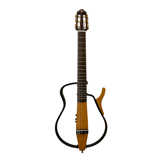
Yamaha Silent Guitar SLG-100N Service Manual
Silent guitar
Hide thumbs
Also See for Silent Guitar SLG-100N:
- Service manual (22 pages) ,
- Owner's manual (17 pages) ,
- Specifications (2 pages)
Advertisement
This document is printed on chlorine free (ECF) paper with soy ink.
EG
011620
20011220-62000
SLG-100N
SERVICE MANUAL
CONTENTS
SPECIFICATIONS
PANEL LAYOUT
CIRCUIT BOARD LAYOUT
DISASSEMBLY PROCEDURE
LSI PIN DESCRIPTION
IC BLOCK DIAGRAM
CIRCUIT BOARDS
INSPECTIONS
............................................................ 12
TUNING
...................................................................... 13
OVERALL CIRCUIT DIAGRAM
PARTS LIST
Guitar
................................................. 3
...................................... 4
................. 6
.............................. 7
.............................. 10
.................................... 10
........................................ 11
........................... 14
HAMAMATSU, JAPAN
1.018K-916
Printed in Japan '02.01
Advertisement
Table of Contents

Related Manuals for Yamaha Silent Guitar SLG-100N


Summary of Contents for Yamaha Silent Guitar SLG-100N
- Page 1 Guitar SLG-100N SERVICE MANUAL CONTENTS SPECIFICATIONS ..........3 PANEL LAYOUT ........4 CIRCUIT BOARD LAYOUT ....6 DISASSEMBLY PROCEDURE ......7 LSI PIN DESCRIPTION ......10 IC BLOCK DIAGRAM ........10 CIRCUIT BOARDS ........11 INSPECTIONS ............12 TUNING ..............13 OVERALL CIRCUIT DIAGRAM ......
- Page 2 IMPOR TANT NOTICE This manual has been provided for the use of authorized Yamaha Retailers and their service personnel. It has been assumed that basic service procedures inherent to the industry, and more specifically Yamaha Products, are already known and under- stood by the users, and have therefore not been restated.
-
Page 3: Specifications
SLG-100N SPECIFICATIONS Neck Mahogany Body Maple Fingerboard Rosewood Bridge Rosewood Frame Unit Maple Strings Nylon Guitar Strings Sensors B-BAND Connectors/Controls • AUX IN • AUX IN Level Control • LINE OUT jack (monaural) • PHONES jack (stereo) • Volume • BASS control •... -
Page 4: Panel Layout
¥ CET APPAREIL NUMÉRIQUE DE LA CLASSE B EST CONFORME ¸ LA NORME NMB-003 DU CANADA. SILENT GUITAR MODEL SLG-100N AC POWER ADAPTOR : YAMAHA PA-1E OR PA-3B OR PA-D09 BATTERY : 9V 6LR61 OR 6F22Y BATTERY : 9V 6LR61 OR 6F22Y MADE IN TAIWAN AUX VOL... - Page 5 ¥ CET APPAREIL NUMÉRIQUE DE LA CLASSE B EST CONFORME ¸ LA NORME NMB-003 DU CANADA. SILENT GUITAR MODEL SLG-100N AC POWER ADAPTOR : YAMAHA PA-1E OR PA-3B OR PA-D09 BATTERY : 9V 6LR61 OR 6F22Y BATTERY : 9V 6LR61 OR 6F22Y MADE IN TAIWAN PHONES ON/OFF switch...
-
Page 6: Circuit Board Layout
SLG-100N CIRCUIT BOARD LAYOUT Body (rear view) Panel Assembly (underneath the panel assembly) Jack... -
Page 7: Disassembly Procedure
SLG-100N DISASSEMBLY PROCEDURE Preparations Make the following preparations; Turn off the power switch. Remove the battery cover and battery. Left Frame (Time required: About 2 minutes) 1-1 Loosen the adjusting bolt (front) marked [E15] and the adjusting bolt (rear) marked [E16]. The left frame can then be removed. - Page 8 SLG-100N (Time required: About 5 minutes) 5-1 Remove the three (3) strings in left side (4 strings) and right side (1 strings) each. (Fig.2) 5-2 Remove the four (4) screws marked [E03] in left and right each. The left and right pegs can then be removed. (Fig.2)
- Page 9 SLG-100N PUP Circuit Board (Time required: About 5 minutes) 8-1 Remove the panel assembly. (See procedure 6.) 8-2 Remove the four (4) screws marked [F02]. The panel holder assembly can then be removed. (Fig.1) 8-3 Remove the PUP circuit board from the two (2) spacers. (Fig.1)
-
Page 10: Lsi Pin Description
SLG-100N LSI PIN DESCRIPTION YSS234 (XN299A00) (Digital Sound Processor) MA: IC01 NAME FUNCTION NAME FUNCTION AVDD DC A+5Vs bus DC D+5V External RAM interface data TST0 DC D+5V TST1 DC D+5V DOEN DC D+5V ... -
Page 11: Circuit Boards
SLG-100N CIRCUIT BOARDS MA Circuit Board Note: See parts list for details of circuit board component parts. Component side Pattern side PUP Circuit Board AUX Circuit Board AUX IN AUX VOL MIN/MAX to Pickup (B-BAND) Component side Pattern side Component side... -
Page 12: Inspections
SLG-100N INSPECTIONS 1. Required Equipment High-sensitivity AC voltmeter (level meter) Battery (006P) or power adapter (PA-D09) 2. Noise Level Measurement Load resistance [PHONES] jack: 39Ω (right and left each) [LINE OUT] jack: 10kΩ (1) Turn on the power to the main unit, turn on the [PHONES] switch, and check that the power LED (green) lights up. -
Page 13: Tuning
SLG-100N TUNING Use a tuning meter, pitch pipe, tuning fork, piano, etc., and to the open strings to the pitches shown below. • If the string’s pitch is high, loosen the string until the string’s pitch is slightly lower than the tuning pitch, then tune while raising the string’s pitch. -
Page 14: Parts List
to Pickup (B-BAND) Note: D7 is not installed. VOLUME SRAM 256K OP AMP PHONES OP AMP Note SYSTEM RESET SYSTEM RESET OP AMP LINE OUT TONE CONTROL AUX VOL OP AMP OP AMP TREBLE 0.012u OP AMP 3.3K AUX IN BASS REVERB OFF/1/2 REGULATOR +8V... -
Page 15: Parts List
Guitar SLG-100N PARTS LIST CONTENTS OVERALL ASSEMBLY ..........2 PANEL ASSEMBLY ......... 4 ELECTRICAL PARTS ..........6 Notes : DESTINATION ABBREVIATIONS A : Australian model M : South African model B : British model O : Chinese model C : Canadian model... -
Page 16: Overall Assembly
SLG-100N OVERALL ASSEMBLY Panel assembly: See page 4. Panel holder assembly F01a F01d F01b F01e F01c F01d... - Page 17 SLG-100N Accessories AC Adapter Stereo Earphones Soft Case PART NO. DESCRIPTION REMARKS REF NO. RANK OVERALL ASSEMBLY SLG-100N Body 24173400 S M6.0XP1 L=13 #0186130 QC665900 S M6.0XP1 L=10 #0186100 QC653700 Left Frame QC655100 Bracket Assembly QC667000 Flat Head Tapping Screw-2 3.0X8(Black Chrome)
- Page 18 SLG-100N PANEL ASSEMBLY...
- Page 19 SLG-100N PART NO. DESCRIPTION REMARKS REF NO. RANK PANEL ASSEMBLY SLG-100N (QC66720) QC659900 Control Panel (Black) QC660200 Battery Cover (Black) V2300100 AUX Knob AUX VOL QC187700 Rotary Knob VOLUME,BASS,TREBLE VC407100 DC Cord Column V8729700 Circuit Board V8729800 Circuit Board QC660100...
-
Page 20: Electrical Parts
SLG-100N ELECTRICAL PARTS PART NO. DESCRIPTION REMARKS REF NO. RANK ELECTRICAL PARTS SLG-100N V8729700 Circuit Board (V872950)(X2450C0) V8729800 Circuit Board (V872950)(X2450C0) V8729900 Circuit Board (V872950)(X2450C0) V8729700 Circuit Board (V872950)(X2450C0) QC662200 LED Holder LEH5-4.5T UA654470 Mylar Capacitor 0.047u 50V J UA354120 Mylar Capacitor 0.012u 50V J... - Page 21 SLG-100N PART NO. DESCRIPTION REMARKS REF NO. RANK UM397470 CC14 Electrolytic Capacitor-KS 47u 16V UU148220 CC15 Electrolytic Capacitor-FW 220u 25V V6796100 CC16 Electrolytic Capacitor-KS 220u 10V V6796100 CC17 Electrolytic Capacitor-KS 220u 10V UM398100 CC18 Electrolytic Capacitor-KS 100u 16V UM397100 CC19...
- Page 22 SLG-100N PART NO. DESCRIPTION REMARKS REF NO. RANK RD359100 Carbon Resistor (chip) 1M 63M J RD356220 Carbon Resistor (chip) 2.2K 63M J RD358100 Carbon Resistor (chip) 100K 63M J RD358100 Carbon Resistor (chip) 100K 63M J RD356100 Carbon Resistor (chip)