
Related Manuals for Mitsubishi Electric PEAD-RP71


Summary of Contents for Mitsubishi Electric PEAD-RP71
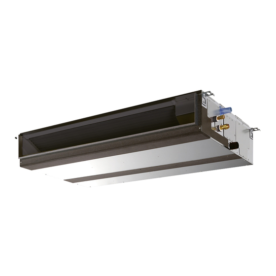
- Page 1 Air-Conditioners PEAD-RP71, 100, 125, 140JAA INSTALLATION MANUAL FOR INSTALLER English For safe and correct use, please read this installation manual thoroughly before installing the air-conditioner unit.
- Page 2 3 10 mm or more D Air outlet 4 300 mm or more E Ceiling surface F Service space (viewed from the side) G Service space (viewed from the direction of arrow) (mm) Model PEAD-RP71 1100 1154 1200 1060 1200 PEAD-RP100, 125 1400...
- Page 3 [Fig. 6-1] øB øA Model PEAD-RP71, 100, 125, 140 ø15.88 ø9.52 a Indoor unit b Outdoor unit [Fig. 6-3] [Fig. 6-4] [Fig. 6-5] 90° a Burr c Spare reamer a Copper tubes c No good e Uneven a Flare nut...
- Page 4 [Fig. 6-10] [Fig. 6-11] A Indoor unit B Tie band (accessory) C Band fixing part D Insertion margin E Drain socket (accessory) F Drain pipe (O.D. ø32 PVC TUBE, field supply) G Insulating material (field supply) A Downward slope 1/100 or more B Connection dia.
- Page 5 [Fig. 7-1] [Fig. 7-2] <A> In case of rear inlet Duct Air inlet Access door Canvas duct Ceiling surface Air outlet Leave distance enough to pre- vent short cycle <B> In case of bottom inlet A Filter B Bottom plate [Fig.
- Page 6 [Fig. 8-2-1] [Fig. 8-2-2] A Screw holding cover (1pc) C Terminal box B Cover D Knockout hole E Remove [Fig. 8-2-3] [Fig. 8-2-4] F Use PG bushing to keep the weight of the cable and external force from being applied to J Terminal block for power source and indoor transmission the power supply terminal connector.
- Page 7 [Fig. 8-3] A Indoor terminal block A Indoor terminal block 4 Always install an earth wire (1-core 1.5 mm longer than other cables B Earth wire (green/yellow) B Earth wire (green/yellow) C Indoor/outdoor unit connecting wire 3- 5 Remote controller cable Wire No ×...
- Page 8 [Fig. 8-7] Standard 1:1 OC(00) Indoor/outdoor wiring Signal receiving unit wiring A Outdoor unit B Refrigerant address C Indoor unit CN90 D Signal receiving unit [Fig. 8-8] A Signal receiving unit external B Center of Switch box C Switch box D Installation pitch E 6.5 mm (1/4 inch) F 70 mm (2 - 3/4 inch)
- Page 9 [Fig. 8-12] Insert the minus screwdriver toward the arrow pointed and wrench it to remove the cover. A flat screwdriver whose width of blade is between 4 and 7mm (5/32 - 9/32inch) must be used. [Fig. 8-13] A Thin-wall portion B Bottom case C Remote controller wire D Conducting wire...
- Page 10 [Fig. 8-16] JP41 JP42 CN32 CN105 CN3C CN41 CN2A CN51 CN22 CN90 CNXB2 CN4F CNXA2 CN44 CN20 CN2L CNXC2 <Indoor controller board> [Fig. 8-17] [Fig. 8-18] CN90 CN90 CN90 CN90 CN90 CN90 CN90 CN90 Pair number: 0 Pair number: 1 Pair number: 2 Pair number: 3 Pair number: 0...
- Page 11 ⁄ Mode number [Fig. 8-21] ⁄ Setting number ⁄ Refrigerant address ⁄ Unit number A Filter button (<Enter> button) B TEST button TEMP. ON/OFF C Set Time button MENU ON/OFF FILTER BACK MONITOR/SET CHECK TEST D Timer On/Off button (Set Day button) PAR-21MAA CLOCK OPERATION...
- Page 12 10.1 [Fig. 10-1] H Refrigerant gas cylinder for R410A with A Indoor unit siphon B Union I Refrigerant (liquid) C Liquid pipe J Electronic scale for refrigerant charging D Gas pipe K Charge hose (for R410A) E Stop valve L Gauge manifold valve (for R410A) F Outdoor unit M Service port G Refrigerant gas cylinder operating valve...
-
Page 13: Table Of Contents
- It may also be in violation of applicable laws. the unit falling or leakage of water. - MITSUBISHI ELECTRIC CORPORATION cannot be held responsible for • Perform electrical work according to the installation manual and be sure to malfunctions or accidents resulting from the use of the wrong type of refrigerant. -
Page 14: Selecting An Installation Site & Accessories
3. Selecting an installation site & Accessories • Select a site with sturdy fixed surface sufficiently durable against the weight of unit. Warning: • Before installing unit, the routing to carry in unit to the installation site should be The unit must be securely installed on a structure that can sustain its weight. If determined. -
Page 15: Refrigerant Piping Work
6. Refrigerant piping work 6.1. Refrigerant pipe [Fig. 6-5] (P.3) a Flare nut [Fig. 6-1] (P.3) b Copper tube a Indoor unit • Remove flare nuts attached to indoor and outdoor unit, then put them on pipe/tube b Outdoor unit having completed burr removal. -
Page 16: Drain Piping Work
6. Refrigerant piping work 1.Remove and discard the rubber bung which is inserted in the end of the unit piping. Tighten the cap to the service port to obtain the initial status. 2.Flare the end of the site refrigerant piping. 3.Pull out the thermal insulation on the site refrigerant piping and replace the insula- Retighten the cap tion in its original position. -
Page 17: Duct Work
7. Duct work • Connect canvas duct between unit and duct. [Fig. 7-1] (P.5) • Use incombustible material for duct parts. • Provide full insulation to inlet duct flange and outlet duct to prevent condensation. • Be sure to change the position of air filter to a position where it can be serviced. <A>... -
Page 18: Electrical Work
8. Electrical work 8.1. Power supply 8.1.2. Separate indoor unit/outdoor unit power supplies (For PUHZ application only) 8.1.1. Indoor unit power supplied from outdoor unit The following connection patterns are available. The following connection patterns are available. The outdoor unit power supply patterns vary on models. The outdoor unit power supply patterns vary on models. - Page 19 8. Electrical work 8.2. Indoor wire connection [Fig. 8-5] (P.7) A For installation in the switch box: Work procedure B For direct installation on the wall select one of the following: 1.Remove 2 screws to detach the electric component cover. •...
- Page 20 8. Electrical work 8.4.2. Signal Receiving Unit [Fig. 8-11] (P.8) H Seal around here with putty 1) Sample system connection I Remote controller wire [Fig. 8-7] (P.8) J Seal around here with putty Only the wiring from the signal receiving unit and between the remote controllers is shown in [Fig.
-
Page 21: Remote Controller
8. Electrical work 2) For wireless remote controller [Fig. 8-22] (P.11) 8.5. Function settings (Function selection via the 1. Changing the external static pressure setting. remote controller) 8.5.1 Function setting on the unit (Selecting the unit functions) • Be sure to change the external static pressure setting depending on the duct and 1) For wired remote controller [Fig. -
Page 22: Test Run
9. Test run 9.1. Before test run 9.2. Test run After completing installation and the wiring and piping of the indoor and outdoor 9.2.1. Using wired remote controller (option) units, check for refrigerant leakage, looseness in the power supply or control 1 Turn on the power at least 12 hours before the test run. - Page 23 9. Test run 4 Press the MODE button B to activate HEAT mode, then check whether warm air 9.3. Test run is blown out from the unit. 9.3.1. Using wireless remote controller (option) 5 Press the FAN button C and check whether fan speed changes. [Fig.
-
Page 24: Maintenance
9. Test run On the wireless remote controller with conditions above, following phenomena takes place. • No signals from the remote controller are accepted. • OPE lamp is blinking. • The buzzer makes a short ping sound. Note: Operation is not possible for about 30 seconds after cancellation of function selection. (Correct operation) For description of each LED (LED1, 2, 3) provided on the indoor controller, refer to the following table. - Page 28 Please be sure to put the contact address/telephone number on this manual before handing it to the customer. HEAD OFFICE: TOKYO BLDG., 2-7-3, MARUNOUCHI, CHIYODA-KU, TOKYO 100-8310, JAPAN KD79D905H02...