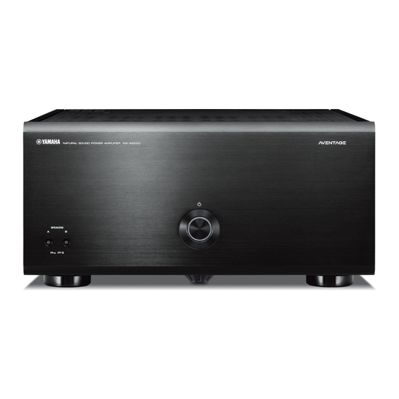
Yamaha MX-A5000 Owner's Manual
Power amplifier
Hide thumbs
Also See for MX-A5000:
- Owner's manual (100 pages) ,
- Connection example (2 pages) ,
- Connection example (2 pages)
Summary of Contents for Yamaha MX-A5000
- Page 1 English Français Deutsch Español Русский Power Amplifier/Ampli de Puissance 中文 한국어 Owner’s Manual Mode d’emploi Bedienungsanleitung Manual de Instrucciones Инструкция по эксплуатации 使用说明书 사용 설명서...
-
Page 2: Precaution For Use
Precaution for use Read the supplied booklet “Safety Brochure” before using the unit. Install the unit in a well ventilated, cool, dry, clean place – away from direct sunlight, Since the unit adopts bare metallic speaker terminals, make sure keeping enough heat sources, vibration, dust, moisture, and/or cold. -
Page 3: Table Of Contents
CONTENTS Accessories Check that the following accessories are supplied with the product. Precaution for use ..........i ... -
Page 4: Features
Unbalanced connections utilize ground-sensing to change in a cascade connection to switch the power of achieve fidelity that is close to balanced transmission. another device such as a Yamaha subwoofer (THROUGH OUT). In addition, another device can be ■ Chassis structure that maximizes... -
Page 5: Part Names And Functions
Part names and functions Front panel SPEAKERS z (power) key SPEAKERS A/B keys Turns on/off (standby) the unit (p.8). Turns on /off the speakers connected to the CH.2 A/B terminals (p.10). Power indicator Lights up when the unit is turned on. If the indicator blinks, the protection circuitry has been •... -
Page 6: Rear Panel
Rear panel SPEAKERS SPEAKERS INPUT TRIGGER +12V CH.5 CH.2 CH.1 CH.2 CH.5 CH.6 CH.6 THROUGH BAL. UNBAL. BAL. UNBAL. BAL. UNBAL. BAL. UNBAL. BAL. UNBAL. CH.5 CH.5 CH. SELECTOR CH. SELECTOR CH. SELECTOR CH. SELECTOR CH. SELECTOR CH. SELECTOR CH. SELECTOR CH.5 CH.6 CH.2... - Page 7 INPUT (XLR) jack INPUT (RCA) jack For connecting to a pre-amplifier with XLR output jacks (p.6). For connecting to a pre-amplifier with RCA output jacks (p.6). To use the XLR jack, set the corresponding BAL/UNBAL switch to “BAL”. To use the RCA jack, set the corresponding BAL/UNBAL switch to “UNBAL”.
-
Page 8: Connections
Connections Caution • Remove the unit’s power cable from an AC wall outlet before making any connections or operating the switches and/or selectors. Connect a pre-amplifier and speakers to the unit. To connect a pre-amplifier, use an XLR balanced cable (for balanced connection) or an RCA unbalanced cable (for unbalanced connection) for each channel depending on the output jacks available on your pre-amplifier. -
Page 9: Connecting Speakers
Connecting speakers ■ Note on the speaker impedance b Loosen the speaker terminal. c Insert the bare wires of the cable into the gap on the side (upper left or bottom right) of the The unit supports the following speaker impedance. terminal. -
Page 10: Connecting The Power Cable
Connecting the power cable Other functions After all the connections and switch operations are complete, connect the supplied power cable to the unit and then to an AC wall outlet. Turning off the unit automatically The unit (rear) (auto-standby function) CTOR CH. -
Page 11: Turning On The Unit In Conjunction With Operating Other Devices (Trigger Function)
If TRIGGER (+12 V) (IN/THROUGH OUT/OUT) jacks you have a power amplifier or a Yamaha subwoofer that supports the trigger function, The unit (rear) Pre-amplifier you can use the trigger function by connecting your devices to the TRIGGER jacks with... -
Page 12: Advanced Speaker Configuration
Advanced speaker configuration Using two pairs of front speakers (SPEAKERS A/B) Caution • Remove the unit’s power cable from an AC wall outlet before making any connections or operating the If you connect two pairs of front speakers to the CH.2 A/B terminals, you can switch the switches. -
Page 13: Appendix
Appendix Input-output signal path diagram INPUT (RCA/XLR) jacks SPEAKERS (R) terminals SPEAKERS (L) terminals CH SELECTOR BAL/UNBAL switch BAL/UNBAL switch CH SELECTOR UNBAL UNBAL CH.6 CH.6 CH.6 CH.6 CH.6 CH.5 CH.5 UNBAL UNBAL CH.5 CH.5 CH.5 UNBAL UNBAL CH.4 CH.4 CH.4 CH.4 CH.4... -
Page 14: Troubleshooting
As a safety precaution, capability to turn on the power is disabled. Contact your consecutively. When the unit is in this condition, the power nearest Yamaha dealer or service center to request repair. indicator on the unit blinks. The power does not turn on. -
Page 15: Specifications
Specifications Input jacks • Rated Output Power (1-channel driven) • Input Sensitivity / Input Impedance Unbalance (1 kHz, 100 W/8 ) ......1.0 V/47 k (1 kHz, 0.9% THD, 6 ) • Audio Balance (1 kHz, 100 W/8 ) ........2.0 V/47 k CH.1 ................230 W/ch Analog RCA (Unbalance) x 11 CH.2 (L/R) ..............230 W/ch... - Page 16 © 2013 Yamaha Corporation Printed in Malaysia ZG28970...
- Page 17 CINEMA DSP (champ sonore 3D à 11.2 voies). By a combination of “AV Pre-Amplifier CX-A5000” and “Power Amplifier MX-A5000”, you can build a home theater system in a variety of ways. This guide explains three representative connection manners for example. Please place the speakers in your room by using the following diagram as a reference.
- Page 18 • Réglez le commutateur BAL/UNBAL et CH. SELECTOR pour chaque voie (à l’arrière du MX-A5000) comme illustré ci-dessus. • Establezca el conmutador BAL/UNBAL y CH. SELECTOR para cada canal (en la parte trasera del MX-A5000) como se indica en la ilustración anterior.


